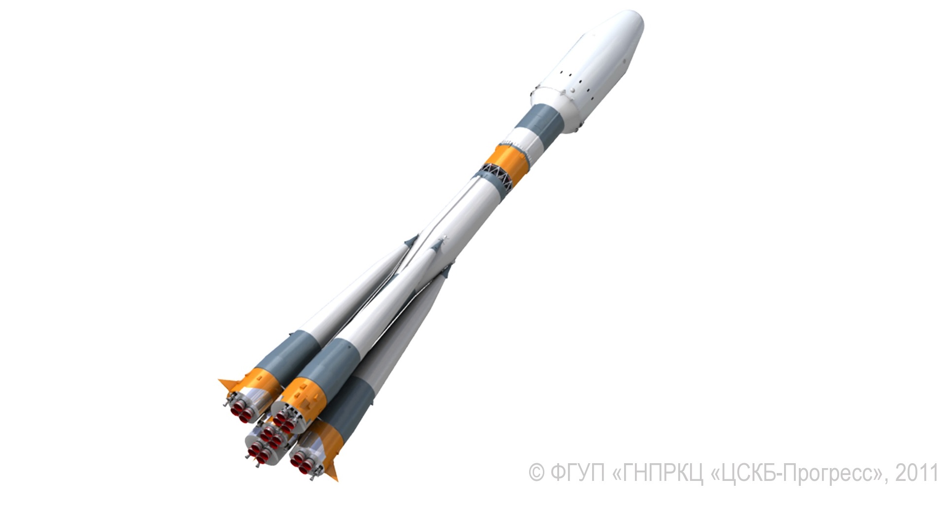
Soyuz 2-1B – Launch Vehicle
Soyuz 2-1B is the next-generation of the Russian workhorse Soyuz Launcher. It is nearly identical to previously flown Soyuz launchers, but features an upgraded Control System switching from analog to digital control system to make the Soyuz Launcher more flexible and an upgraded third stage featuring the RD-0124 Engine.
The vehicle is a member of the Soyuz Rocket Family that has a history dating back to 1957. Soyuz launchers have been derived from the R-7 missile that was developed during the Cold War making 28 launches between 1957 and 1961.
There have been various different versions of the Soyuz Launcher. The Soyuz 2 Launcher Family is currently operating alongside the Soyuz-U and FG Launcher and is planned to replace these vehicles once they are phased out.
Soyuz 2-1B Rockets are being operated from the Baikonur Cosmodrome (LC-31), LC-43 at Plesetsk Cosmodrome and the Kourou Space Center in French Guiana. The Launcher is available to Russian Government Customers as well as commercial customers via the Arianespace affiliate Starsem that operated the Soyuz launcher.
With its new digital control system, Soyuz 2-1B can perform more flexible Ascent Missions. The old Soyuz Launchers had to be rotated on their launch tables to the correct launch azimuth angle since their control system was not able to perform a Roll Maneuver early in the flight. With the new digital control System, the launch table does not need to be rotated since the digital control system supports three-axis vehicle control from the point of liftoff. The digital controller also provides more stability during ascent, allowing the Soyuz to be outfitted with larger Payload Fairings enabling it to carry bigger payloads. The old Soyuz control system was unable to handle the instabilities caused by a larger fairing. In addition, the Soyuz 2 generation of vehicles provides a significantly higher injection accuracy that is important for direct-to-orbit flights. The Soyuz 2-1B has a higher payload capability than the Soyuz 2-1A that is using the conventional third stage design.
Soyuz 2-1B is usually outfitted with a Fregat Upper Stage that features its own autonomous control system that takes over after the Soyuz has released the Orbital Unit. Fregat provides more injection accuracy and is able to make several engine burns during the flight to allow payloads to be delivered to a variety of orbits including Low Earth Orbit, Sun-Synchronous Orbit, Geosynchronous transfer orbit and Geosynchronous Orbit. By launching from three Launch Sites around the Globe, Soyuz 2 can target a variety of orbital inclinations.
Soyuz 2 is manufactured by TsSKB-Progress of Samara, Russia.
Soyuz 2-1B Specifications
| Type | Soyuz 2-1B |
| Manufacturer | TSSKB-Progress |
| Height | 46.1m |
| Diameter | 2.95m |
| Launch Mass | 303,000kg |
| Mass to LEO | 7,800kg |
| Mass to MEO | 1,645kg |
| Mass to GTO | 3,250kg |
| Mass to SSO | 4,400kg |
| Mass to GEO | 1,440kg |
The Soyuz-2 Vehicle stands 46.1 meters tall and has a main diameter of 2.95 meters and a span of 10.3 meters from booster fin to booster fin.
All stages of the vehicle use Rocket Propellant 1 (Rocket-Grade Kerosene) and Liquid Oxygen as propellants. Liftoff mass is about 303,000 Kilograms, excluding payload and upper stage mass.
The 2-1B version of the Soyuz can deliver payloads of up to 7,800 Kilograms to Low Earth Orbit featuring a slightly improved performance over the previous Soyuz Vehicles, making it suitable for launches of heavy satellites targeting Low Earth Orbits.
With an appropriate Upper Stage like Fregat, Soyuz can reach a variety of orbits including Sun Synchronous, Medium Earth and Geostationary Transfer Orbit. Direct Geostationary Insertions and Escape Missions are also possible, primarily for small spacecraft
Boosters
| Boosters | 4 |
| Length | 19.60m |
| Diameter | 2.68m |
| Dry Mass | 3,784kg |
| Launch Mass | 44,413kg |
| Oxidizer | Liquid Oxygen |
| Fuel | Rocket Propellant-1 |
| Oxidizer Mass | 27,900kg |
| Fuel Mass | 11,260kg |
| Guidance | From 3rd Stage |
| Tank Pressurization | Nitrogen |
| Propulsion | 1 RD-107A (4 Chambers) |
| Engine Type | Gas Generator |
| Thrust at Sea Level | 838.5kN |
| Thrust (Vacuum) | 1,021.3kN |
| Impulse | 263s (SL) – 320s (Vac) |
| Engine Length | 1.85m |
| Engine Diameter | 2.57m |
| Engine Dry Weight | 1,250kg |
| Burn Time | 120 sec |
| Chamber Pressure | 61.2bar |
| Ox. To Fuel | 2.47 |
| Throttle Capability | Yes |
| Engine Start | Spark |
| Restart Capability | No |
| Turbopump Prop | Hydrogen Peroxide (1,190kg) |
| Attitude Control | 2 Vernier Jets |
| Vernier Thrust | 35kN |
| Shutdown | Commanded Shutdown |
| Separation | Pyronuts, Pushers, Reaction Nozzle |
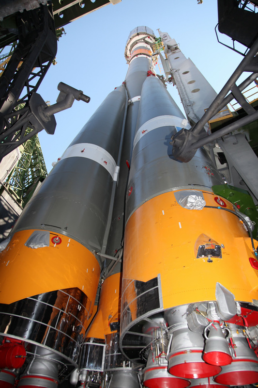
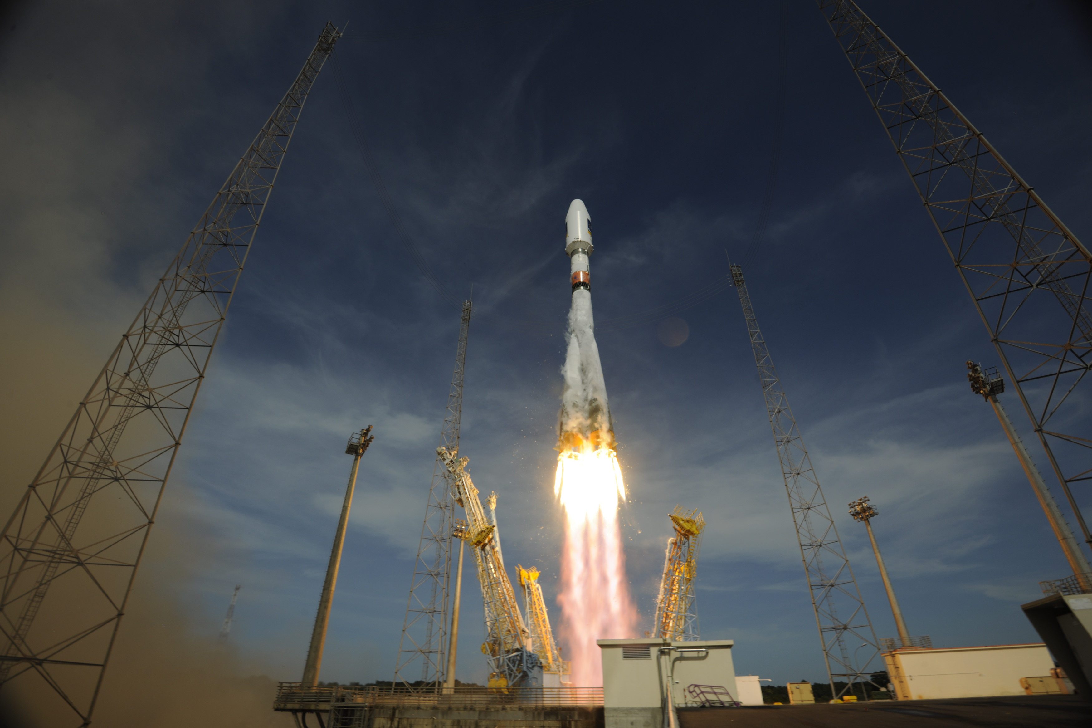
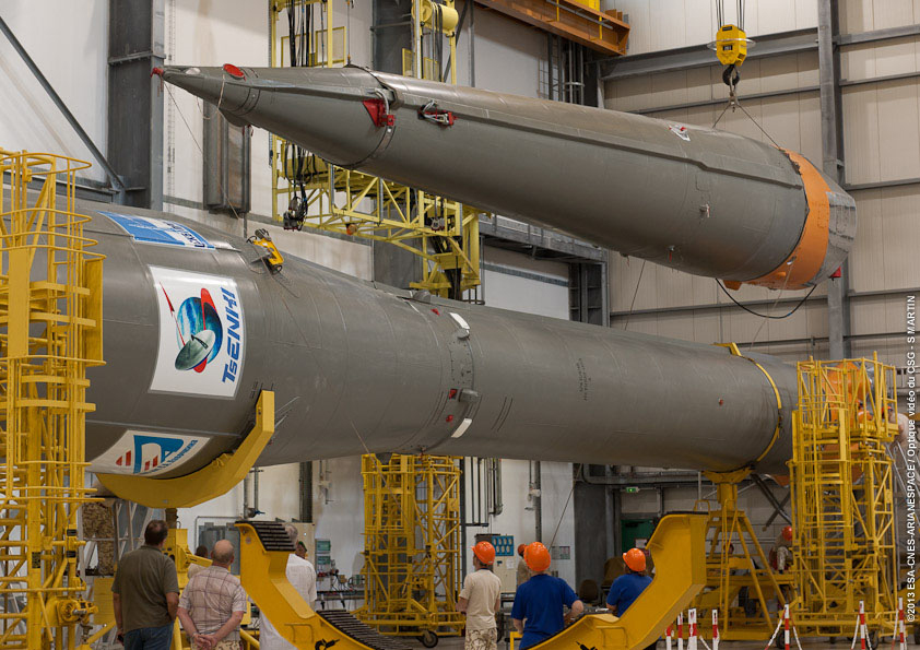
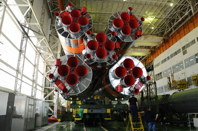
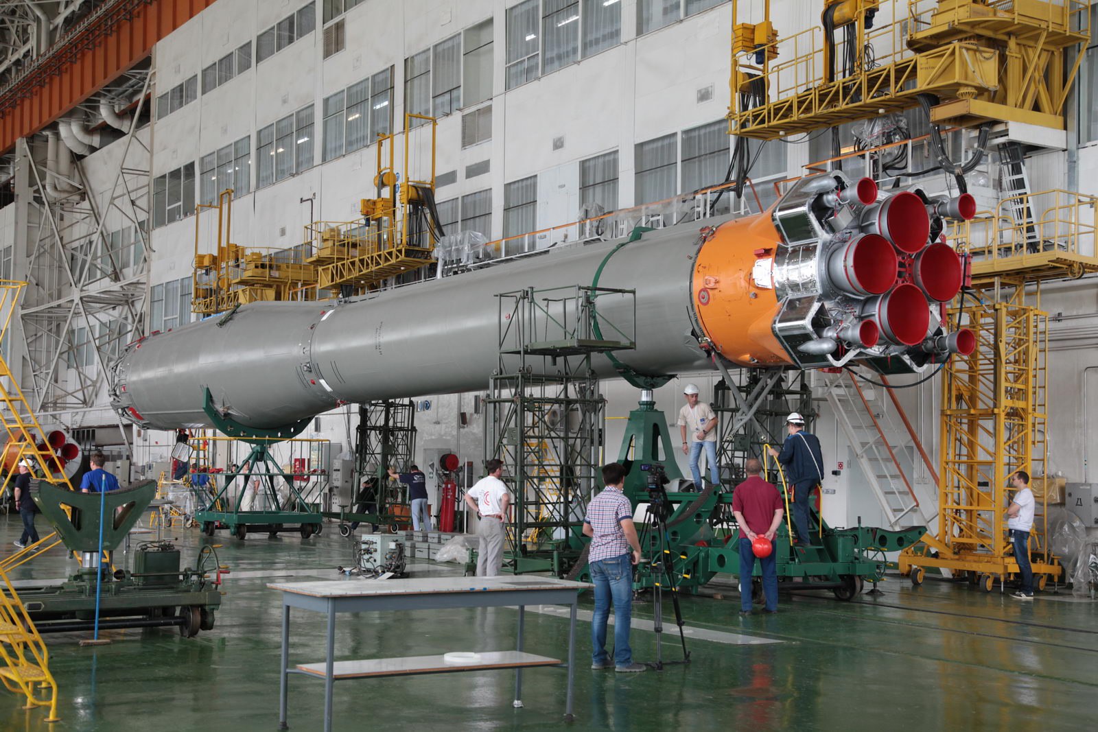
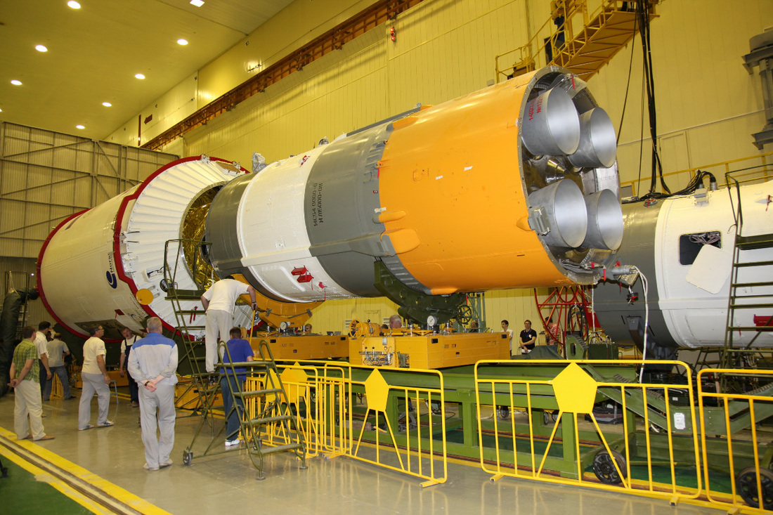
Soyuz 2 is outfitted with four liquid fueled strap-on boosters providing extra lift during the initial phase of the flight. All four boosters are ignited before liftoff to reach full thrust and are jettisoned once their fuel tanks are empty.
The boosters are arranged around the central Core Stage and are tapered cylinders. The Oxidizer Tank is in the tapered portion of the booster while the fuel tank is inside the cylindrical portion.
Each booster holds a total of 39,160 Kilograms of Propellants which are Liquid Oxygen and Rocket Propellant 1. A Soyuz Booster is 19.6 meters in length and 2.68 meters in diameter.
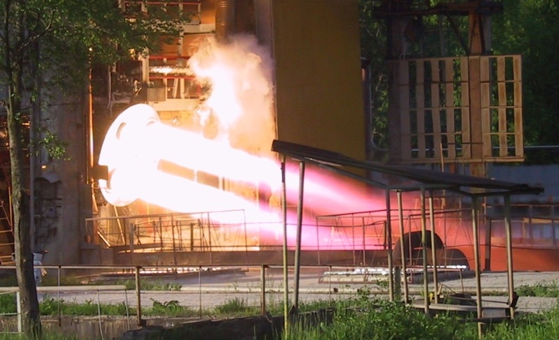
An RD-107A Engine is installed on each booster providing a thrust of 837.5 Kilonewtons at Liftoff. RD-107A is an improved version with more efficient fuel injection, but it is very similar to the RD-107 engines of previous Soyuz Launchers. The engine utilizes a spark ignition system and can not be re-started.
RD-107A features four combustion chambers that are fed by a Turbopump transferring 91 Kilograms of Kerosene and 226 Kilograms of Oxygen every second. Several auxiliary pumps are used to keep the Propellant Tanks at flight pressure by feeding them with vaporized Nitrogen.
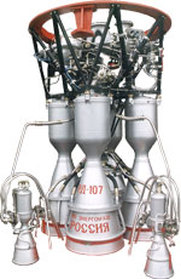
Another pump delivers Hydrogen Peroxide to the main pump to power it. A total of 1,190 kilograms of Hydrogen Peroxide and 280 Kilograms of liquid Nitrogen are stored inside spherical tanks and are expended during ascent for the aforementioned purposes. The Turbopump spins at over 8,000rpm at flight speed. The four nozzles of the RD-107A can not be gimbaled, but the engine is outfitted with two 35kN vernier jets that can be used for attitude control. Also, an aerofin is installed on the base of the booster and also contributes to attitude stability. The engine has a dry weight of 1,250 Kilograms and is 2.57 meters in length and 1.58 meters in diameter.
All boosters ignite about 17 seconds before launch to allow the Turbopumps to spin up to flight speed. Also, the engines are being monitored during that period to make sure performance is nominal. The Boosters Burn for 118 seconds following liftoff before being separated from the launch vehicle and impacting downrange.
Core Stage
| Diameter | 2.95m |
| Length | 27.8m |
| Empty Mass | 6,545kg |
| Launch Mass | 99,765kg |
| Oxidizer | Liquid Oxygen |
| Fuel | Kerosene |
| Oxidizer Mass | 63,800kg |
| Fuel Mass | 26,300kg |
| Tank Pressurization | Nitrogen |
| Guidance | From 3rd Stage |
| Propulsion | 1 RD-108A |
| Engine Type | Gas Generator |
| Propellant Feed | Turbopump |
| Total Thrust SL | 792.5kN |
| Total Thrust Vac | 990.2kN |
| Engine Length | 2.87m |
| Engine Diameter | 1.95m |
| Engine Dry Weight | 1,075kg |
| Burn Time | 280s |
| Specific Impulse | 258s (SL) 321s (Vac) |
| Chamber Pressure | 55.5bar |
| Ox to Fuel Ratio | 2.47 |
| Throttle Capability | Yes |
| Engine Start | Spark |
| Restart Capability | No |
| Attitude Control | 4 Vernier Thrusters |
| Vernier Thrust | 35kN |
| Shutdown | Commanded Shutdown |
| Separation | Pyronuts, 3rd Stage Exhaust |
The Core Stage of the Soyuz Vehicle acts as both, first and second stage. It is ignited prior to blastoff and continues to power the launcher after Booster Jettison as the second stage.
The Core Stage is 27.8 meters long and 2.95 meters in diameter. It is equipped with a large Oxidizer Tank and a Fuel Tank beneath it, both holding a total of 90,200 Kilograms of Propellants.
Where the boosters interface with the core stage, a load carrying ring is installed to transfer loads from the boosters to the vehicle. On top of the core stage is a Truss Segment that interfaces with the upper stage and includes stage separation mechanisms.
The core stage is powered by an RD-108A Engine which is similar to the Booster Main Engine. It also features four combustion chambers and the same pump design. The main Turbopump is also powered by Hydrogen Peroxide. 2,600 Kilograms are consumed during the burn of the stage. 520 Kilograms of liquid Nitrogen are used to keep the Propellant Tanks at flight pressure during the ascent.
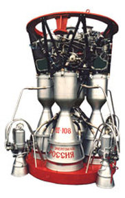
RD-108A provides 792.5 Kilonewtons of Thrust at Launch. Vacuum Thrust is 990.2 Kilonewtons making the engine slightly more powerful than the RD-108 engine. The Engine has a dry weight of 1,075 Kilograms and operates at a chamber pressure of 55.5 bar.
Four 35kN Vernier Engines can be gimbaled to provide three-axis-attitude control during the ascent phase of the mission. The first stage is ignited 17 seconds before liftoff for performance monitoring. The Stage burns for 290 seconds before separating from the third stage. The two stages are separated by igniting the third stage to push the core stage away from the stack. During second stage flight, the protective Payload Fairing is jettisoned to increase launcher performance.
Third Stage
| Diameter | 2.66m |
| Length | 6.74m |
| Empty Mass | 2,355kg |
| Launch Mass | 27,755kg |
| Oxidizer | Liquid Oxygen |
| Fuel | Rocket Propellant 1 |
| LOX Mass | 17,800kg |
| Kerosene Mass | 7,600kg |
| Tank Pressurization | Helium |
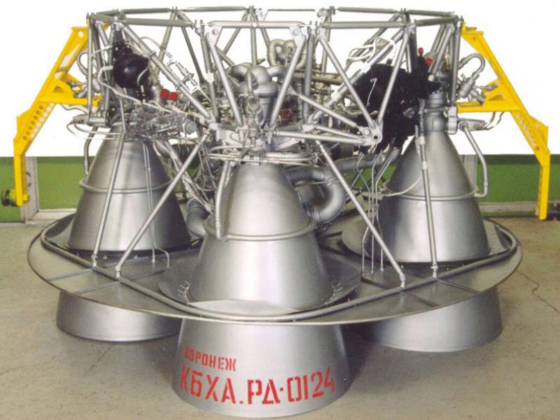
| Propulsion | 1 RD-0124 |
| Engine Type | Staged Combustion Engine |
| Cycle | Closed Cycle |
| Propellant Feed | Turbopump |
| Comb. Chambers | 4 |
| Total Thrust Vac | 294.3kN |
| Engine Length | 1.58m |
| Engine Diameter | 2.40m |
| Engine Dry Weight | 572kg |
| Thrust-to-Weight | 62.5 |
| Burn Time | 230s |
| Specific Impulse | 359s (Vac) |
| Chamber Pressure | 162bar |
| Restart Capability | No |
| Ox to Fuel Ratio | 2.6 |
| Turbine Temp. | 973K |
| LOX Flow Rate | 56.7kg/s |
| RP-1 Flow Rate | 23.9kg/s |
| Attitude Control | Engine gimbaling; Reaction Nozzle |
| Shutdown | Commanded Shutdown |
The third stage of the Soyuz 2-1B is 6.74 meters in length and 2.66 meters in diameter. It also uses the conventional design with the Fuel Tank being placed on top of the Oxygen tank.
Instead of using a spherical fuel tank sitting atop the oxidizer tank, the modified Block I stage features a Kerosene tank with a flat aft bulkhead, a cylindrical section and an forward bulkhead – welded together to increase the capacity of the tank. This also allowed the cylindrical section of the oxidizer tank to be stretched to hold more propellant.
The Avionics of the Soyuz Launcher are also installed on the Upper Stage. These present the main difference between Soyuz 2 and other versions. The control system features a digital onboard computer providing all vehicle commanding and guidance is provided by a 3-axis Inertial Measurement Unit. The control equipment provides vehicle control, telemetry and navigation for the entire flight and issue all vehicle commands autonomously. The equipment is located in the area between the two propellant tanks inside a small equipment bay. The third stage tanks are capable of holding 25,400 Kilograms of Propellants for consumption by the RD-0124 engine.
The RD-0124 is a four-chamber engine with a single Gas Generator and turbopump assembly supplying all combustion chambers. This engine is derived from the RD-0110, but is a closed-cycle gas-generator type engine. Overall, RD-0124 is 2.4 meters in diameter and 1.58 meters tall with an empty mass of 572 Kilograms. The engine delivers a thrust of 294.3 Kilonewtons (30,400kgf) and has a specific impulse of 359 seconds – a major improvement over the RD-0110 due to the use of a closed cycle and the higher chamber pressure of that design.
The RD-0124 uses a typical staged combustion cycle of Russian engines with an Oxygen-rich gas generator in which the entire LOX flow is combusted with a small portion of the fuel flow to create a hot high-pressure gas to drive the turbine of the engine which powers the turbopumps. The rest of the Kerosene is used for cooling of the chambers before being injected into the combustion chambers and burned with the oxygen-rich gas.
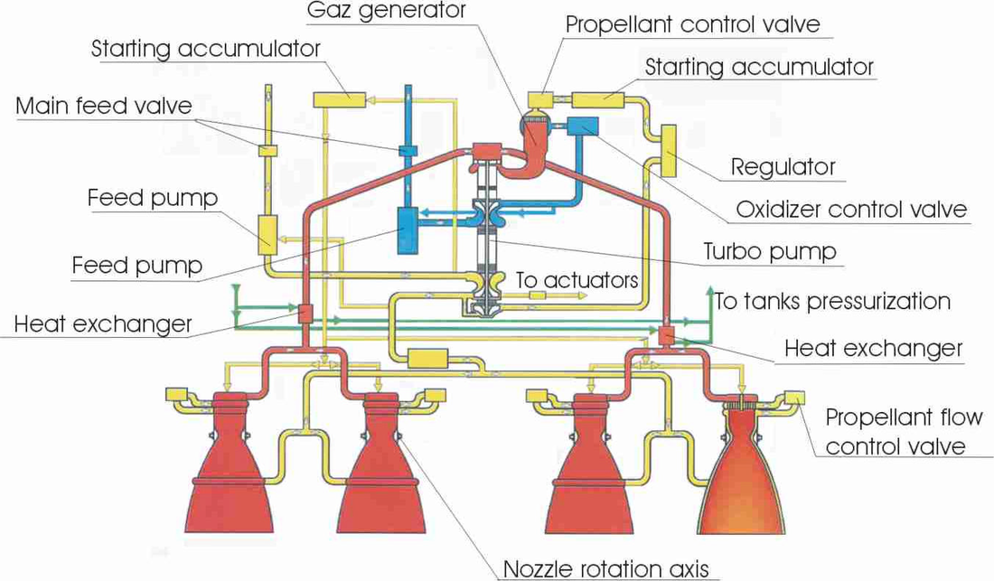
Propellants entering the engine are pumped to the main turbopumps by separate boost pumps in the Kerosene and LOX lines needed to reach the proper inlet pressure of the main pumps. The turbo-axial boost pumps are similar in design – each unit includes one rotating part that consists of axial pump wheels and a hydraulic turbine, brazed or welded onto the pump wheel external diameter.
The boost pump of the fuel inlet is driven by the high-pressure tapoff from the second stage Kerosene turbopump that re-enters the propellant inflow after passing through the turbine. On the LOX side, the boost pump turbine uses a similar scheme – it is powered by a fraction of LOX from the turbopump that also re-enters the feedline.
RD-0124A uses a single shaft to which the LOX turbopump and a two-stage Kerosene turbopump are mounted. The shaft is driven by a turbine powered by the high-pressure gas produced by the Gas Generator.
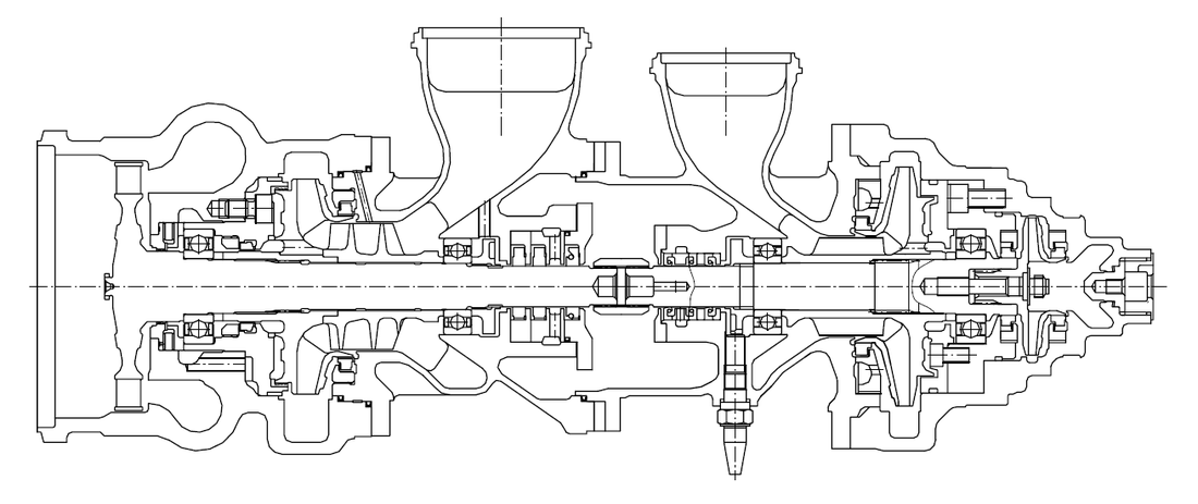
The turbopump housings and impellers are castings made from stainless steel. The impeller seals use bronze floating rings and the pump rotors employ a thrust balance system to ensure a proper axial balance. Both pumps use their respective propellants to lubricate and cool the turbopump ball bearings. The LOX turbopump operates at an inlet pressure of around 3 bar and an outlet pressure of 363 bar at a LOX mass flowrate of 56.7 Kilograms per second. For the Kerosene pump, inlet pressures of under 2 bar are sufficient to allow the pump to generate an outlet pressure of 366 bar at a flowrate of 23.9kg/sec.
The entire LOX flow from the turbopump is passed through an oxidizer control valve to the Gas Generator where it combusts the Kerosene supplied by the second stage of the turbopump via a propellant control valve and a regulator that adjusts the mixture ratio that is normally set at 2.34. The Gas Generator produces a hot gas (973K) entering the turbine at a pressure of 319 bar and a flowrate of 59.85 Kilograms per second. Spinning the turbine at 39,000 rpm, the hot gas exits at a pressure of 185 bar, being directed on two paths that are then further separated into four lines to feed the four combustion chambers.
While still at the two-line stage, the hot gas passes through heat exchangers to warm up the Helium gas supply for tank pressurization. Helium is stored in five spherical tanks submerged in the LOX tank and supplied to the engine to be heated up and pressurized in order to be able to pressurize the Kerosene and LOX tank via a number of pressure regulators and valves that ensure proper pressure levels are maintained.
The Kerosene from the first stage turbopump is directed to the combustion chambers where it is used to cool the chambers and nozzles as part of two circuits per engine chamber. Afterwards, the Kerosene enters the combustion chambers where it is burned by the oxygen-rich gas generator gas supply. The chambers use a mixing head for a stable combustion process and operate at a nominal chamber pressure of 157 bar.
Engine ignition is accomplished by injecting a pyrophoric substance into the Gas Generator and the four chambers that ignites when coming into contact with the oxygen. Once started, the combustion process is sustained by injecting the Kerosene into the GG and combustion chamber. As the gas generator starts spinning the turbine, the turbopumps begin supplying propellants to the Gas Generator and chambers to continue the combustion process. The pyrophoric igniter fluid is stored in accumulators just ahead of the Gas Generator and the chambers that release the fluid once the Kerosene pressure is sufficient to break the membranes.
A small fraction of the Kerosene flow from the first turbopump stage is used to drive the hydraulic actuators of the engine that allow each chamber of be moved by +/-3.5 degrees in one direction. With four chambers being able to move along different directions, attitude control in pitch, yaw and roll can be accomplished. Following payload separation, the Block I stage uses a reaction nozzle that vents the oxygen tank in order to move away from the separated spacecraft.
Fregat Upper Stage
| Type | Fregat Upper Stage |
| Diameter | 3.35m (Fregat) to 3.38m (MT) |
| Length | 1.55m (Fregat) to 1.85m (MT) |
| # Propellant Tanks | 4 |
| # Avionics Tanks | 2 |
| Fuel | Unsymmetrical Dimethylhydrazine |
| Oxidizer | Nitrogen Tetroxide |
| Fregat | |
| Inert Mass | 930kg |
| Propellant Mass | 5,250kg |
| Launch Mass | 6,200kg |
| Fregat-M | |
| Inert Mass | 960kg |
| Propellant Mass | 5,750kg |
| Tanks | Small Tank Extensions |
| Launch Mass | 6,710kg |
| Fregat-MT | |
| Inert Mass | 1,050kg |
| Propellant Mass | 7,100kg |
| Tanks | Large Tank Extensions |
| Launch Mass | 8,150kg |
| All Fregat Stages | |
| Propulsion | S5.92 |
| Type | Turbopump-fed |
| Thrust at Level 1 | 19.85kN |
| Thrust at Level 2 | 14.00kN |
| Impulse | 331s |
| Dry Mass | 80kg |
| Engine Length | 1.03m |
| Engine Diameter | 0.84m |
| Chamber Pressure | 6.85 to 9.8 MPa |
| Startup Time | 2.5 to 3.0sec |
| Burn Time | Variable – Up to 900 sec |
| Restart Capability | Up to 20 Restarts |
| Attitude control | Main Engine Translation (Pitch, Yaw) |
| 8 Hydrazine Thrusters (Pitch, Yaw) | |
| 4 Hydrazine Thrusters (Roll) | |
| ACS Thrusters | S5.221 |
| ACS Thrust | 50N |
| ACS Propellant | 85kg |
| Separation | Gas pressure Locks/Pushers |
| Shutdown | Commanded/Depletion |
| Operation Lifetime | Up to 48 hours |
| Flight Computer | Biser 6 |
| Navigation | 3-axis Platform (Gyros, GPS) |
To increase Launch Vehicle performance and provide precise injection capabilities, the Soyuz FG can be outfitted with a Fregat Upper Stage that is capable of performing several burns to target a variety of different orbital trajectories.
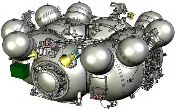
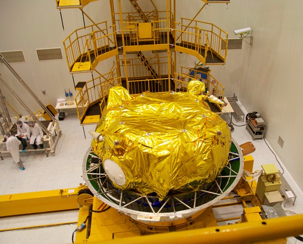
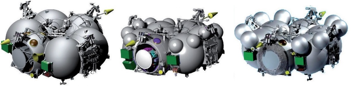
Fregat is an autonomous Upper Stage that is equipped with its own power, propulsion and control system to perform flights of up to 48 hours. The upper stage consists of six spherical tanks (four for propellant, two for avionics) arrayed in a circle, with trusses passing through the tanks providing structural support. NPO Lavochkin of Moscow is responsible for the production of Fregat.
The conventional Fregat upper stage measures 3.35 meters in diameter and is 1.55 meters in length with six propellant tanks. Four tanks hold propellants, two are filled with Unsymmetrical Dimethylhydrazine and two contain Nitrogen tetroxide Oxidizer.
The other two ‘tanks’ are used to facilitate the avionics including the Biser-6 flight computer and the batteries. This allows for a simplified manufacturing process and provides a simple solution for environmentally controlling the systems.
Fregat is available in several configurations – Soyuz uses the conventional Fregat, the Fregat-M and the Fregat-MT.
In the Fregat-M version, the upper stage features propellant tank extensions. Two spherical extensions are welded to each of the four main propellant tanks – these extensions add 30kg in mass to the stage and hold up to 500kg of additional propellant. The MT version uses larger extension tanks that weigh 120 Kilograms and carry 1,850kg of additional hypergolic propellant.
These tank extensions have been developed to allow Fregat to carry more propellant while maintaining its normal mass characteristics for easy flight program development. Anther version, Fregat-SB, is used on the Zenit Rocket carrying an additional toroidal propellant tank.
Fregat uses heritage components to provide high reliability during its missions. The S5.92 Main Engine has been in use for more than 30 years and the Control System of the Vehicle features redundant components and has been used on a number of missiles and launch vehicles.
Fregat uses heritage components to provide high reliability during its missions. The S5.92 Main Engine has been in use for more than 30 years and the Control System of the Vehicle features redundant components and has been used on a number of missiles and launch vehicles.
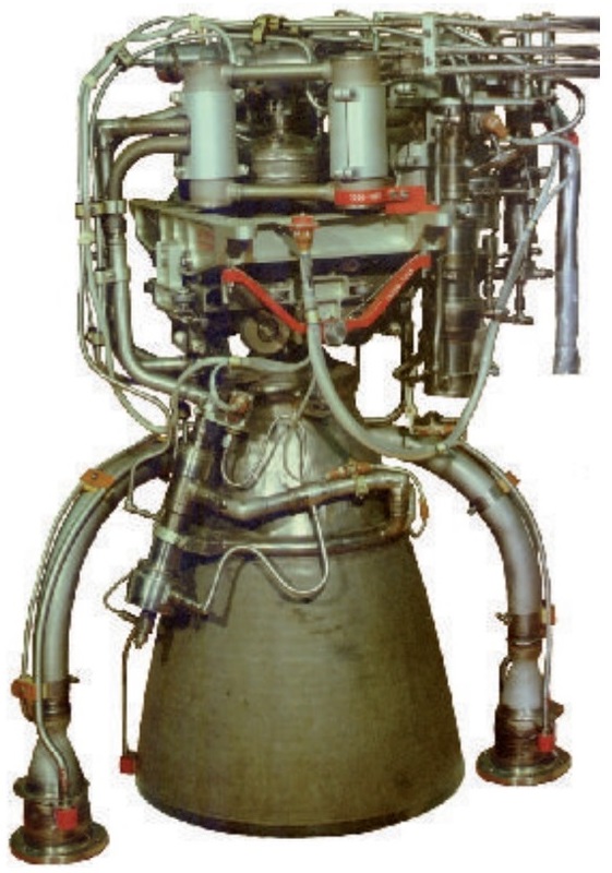
The S5.92 main engine of the Fregat upper stage is a hyperbolic turbopump-fed main engine that uses a staged combustion cycle. A small amount of propellant is burned inside a gas generator that drives the turbine powering the turbopumps for the oxidizer and fuel. The exhaust is expelled via two nozzles. Propellants injected into the main combustion chamber are responsible for generating the majority of the thrust of the engine.
S5.92 can be operated at a full thrust level of 19.85 Kilonewtons and a reduced thrust level of 14kN, allowing it to fly a variety of mission profiles. The engine is 0.84 meters in diameter and 1.03 meter long, with an inert mass of 80 Kilograms. Depending on the thrust setting, the engine operates at a chamber pressure of 6.85 to 9.8 MPa and generates a specific impulse up to 331 seconds. It can be re-started up to 20 times.
The main engine can be gimbaled to provide pitch and yaw control during operation. For roll control during burns and three-axis control in coast phases, Fregat is equipped with 12 S5.221 attitude control thrusters. These thrusters use Hydrazine monopropellant stored in two tanks that are installed on Fregat, containing up to 85kg of propellant.
The thrusters are installed in four pods – each pods contains two pitch/yaw thrusters and one roll thruster, each delivering 50 Newtons of thrust. The thrusters are also used for propellant setting burns ahead of main engine firings.
Pressurization of the main propulsion system and the attitude control system is accomplished using high-pressure Helium that is stored in spherical tanks, each with a volume of 23 liters. The number of tanks depends on the version of Fregat that is used and the chosen flight profile. Fregat is also used for pneumatics – valve and engine actuation.
Fregat, Fregat-M & Fregat-MT
Payload Fairing
| Type 1 | ST Fairing |
| Length | 11.433m |
| Diameter | 4.110m |
| Type 2 | S Fairing |
| Length | 7.700m |
| Diameter | 3.715m |
| Separation | Mech. Locks, Pneumatic, Pushers |
| Construction | Two half-shell carbon-fiber |
| reinforced plastic |
The Payload Fairing is positioned on top of the stacked vehicle and its integrated payloads. It protects satellites or other spacecraft against aerodynamic, thermal and acoustic environments that the vehicle experiences during atmospheric flight. When the launcher has left the atmosphere, the fairing is jettisoned by pyrotechnically initiated systems. It is separated during second stage flight.
At that point, aerodynamic and thermal loads are acceptable for the spacecraft to be exposed after the launcher has left the dense portion of the atmosphere. For the Soyuz 2-1B, there are two basic versions of the Payload Fairing, the conventional S-Type Fairing that is 7.7 meters in length and 3.72 meters in diameter or a longer ST-Fairing that is 11.43 meters long and 4.1 meters in diameter.
Payload Adapters
| PAS 937S | 110kg |
| PAS 1994 VS | 115kg |
| PAS 1666 MVS | 135kg |