
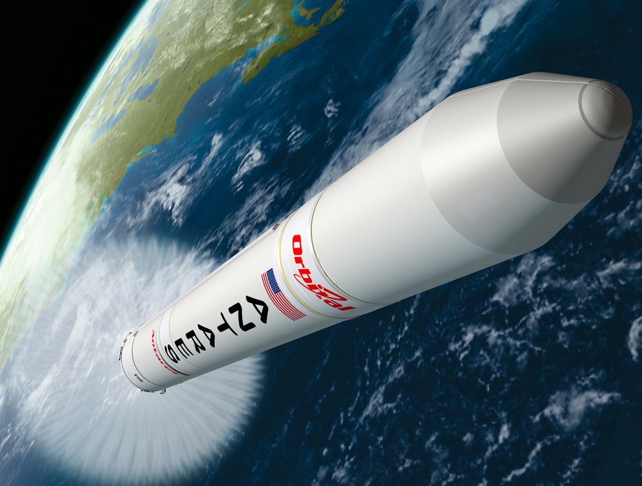
Antares (100 Series)
Antares is an expendable launch system being developed and operated by Orbital Sciences Corporation. It is a two stage launch vehicle with an optional third stage. The launcher can reach a variety of orbits including Low Earth Orbit, Sun Synchronous Orbit, Geosynchronous Transfer Orbit and Interplanetary Trajectories.
Antares is currently being operated from the Mid-Atlantic Regional Spaceport at NASA’s Wallops Flight Facility, however, the vehicle is also compatible with the Western Range at Vandenberg Air Force Base, the Eastern Range at Cape Canaveral Air Force Station and the Kodiak Launch Complex, Alaska.
Orbital Sciences developed Antares under a Commercial Orbital Transportation Services (COTS) contract that the company was awarded from NASA to demonstrate cargo deliveries to the International Space Station. Orbital uses the Antares launcher to boost its Cygnus Capsule to orbit for flights to ISS. Once completing COTS, Orbital enters the Commercial Resupply Services Program. NASA has booked eight ISS resupply flights of Cygnus under Commercial Resupply Services for a total contract volume of $1.9 billion. Antares is also on the market for small and medium missions.
The launch vehicle was originally known as Taurus II, but was renamed in late 2011. Antares made its first flight in April 2013.
Antares Specifications
| Type | Antares |
| Height | 40.5m |
| Diameter | 3.90m |
| Launch Mass | 282,000kg (110) – 296,000kg (130) |
| Mass to LEO | 5,100kg (130) |
| Mass to GTO | 1,800kg (132) |
| Mass to SSO | 3,600kg (131) |
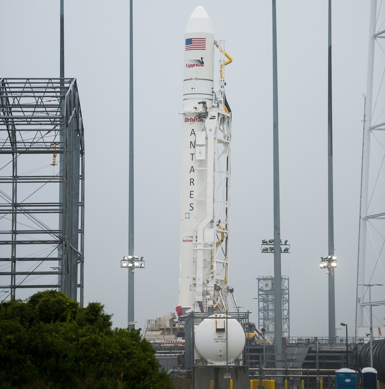
The Antares launch vehicle stands 40.5 meters tall, has a main diameter of 3.9 meters and a liftoff mass of approximately 282,000 Kilograms. It uses a liquid fueled first stage that is powered by two powerful engines.
The second stage of the vehicle is a solid-fueled rocket motor built by Alliant Techsystems. As a second stage, the ATK Castor 30A, 30B and XL can be used. For Cygnus missions to ISS, Antares will fly with two stages only, but other payloads may require a third stage.
Two third stages are available for Antares, the Orbital-built Bi-Propellant Upper Stage that allows Antares to perform precise injections into a variety of orbits and the ATK Star 48 Solid Upper Stage that can be used to reach high-energy orbits. Antares is topped by a 3.94-meter payload fairing.
First Stage
| Type | S1 Core Stage, Zenit Heritage |
| Bays | 5 |
| Dry Mass | 18,700kg |
| Launch Mass | 260,700kg |
| Diameter | 3.90m |
| Length | 27.6m |
| Fuel | Rocket Propellant 1 |
| Oxidizer | Liquid Oxygen |
| Fuel Mass | 64,740kg |
| Oxidizer Mass | 177,260kg |
| Tank Pressurization | Helium, up to 220bar |
| # Helium Bottles | 8 |
| Propulsion | 2 x AJ-26-62 (Modified NK-33) |
| Throttling | 56% – 108% |
| AJ-26 SL Thrust | 1,510kN (100%) – 1,630kN (108%) |
| AJ-26 Vac Thrust | 1,682kN (100%) – 1,815kN (108%) |
| Throttling | 56% – 108% (Up to 135% achieved) |
| Impulse SL | 297s |
| Impulse Vac | 331s |
| Engine Length | 3.71m |
| Engine Diameter | 2.0m |
| Engine Dry Weight | 1,235kg |
| Thrust to Weight | 137 |
| Chamber Pressure | 145bar |
| Area Ratio | 27 |
| Ox. To Fuel Ratio | 2.8 |
| Burn Time | 235sec |
| Attitude Control | Hydraulic TVC for Yaw, Pitch & Roll |
| Stage Separation | Hold Down Bolt Release |
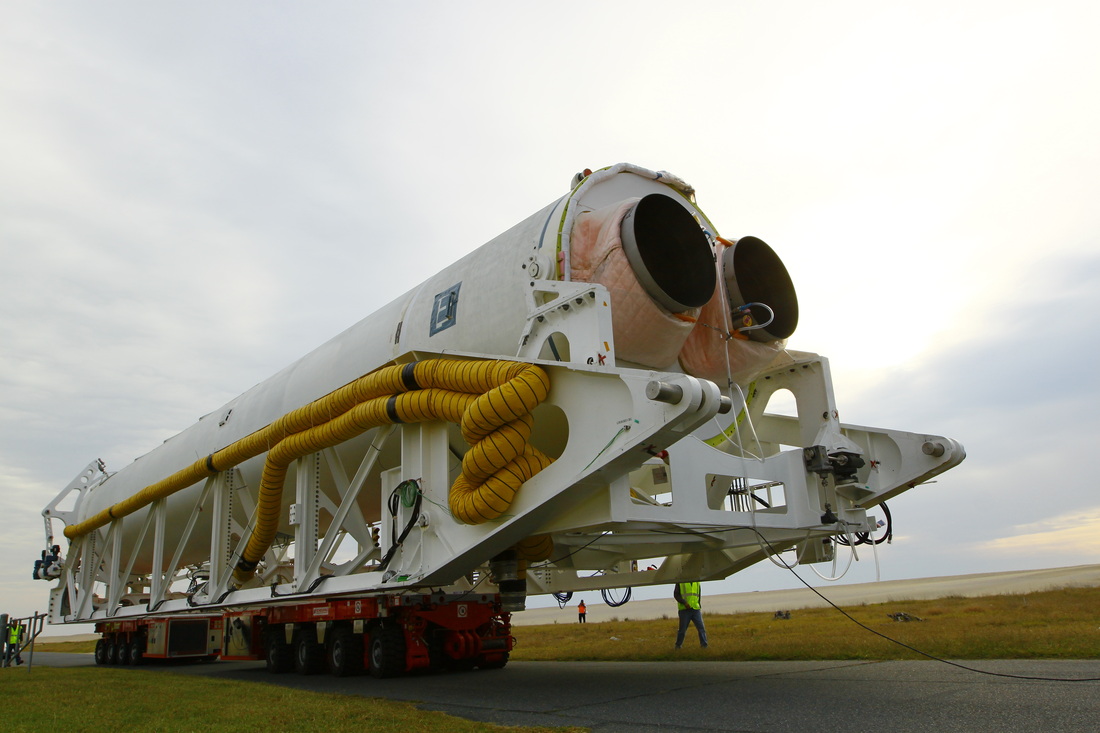
Antares’ first stage is designed by Yuzhnoye and built by Yuzhmash in the Ukraine. It is 27.6 meters long and 3.9 meters in diameter and contains Liquid Oxygen oxidizer and Rocket Propellant 1 fuel.
The Stage 1 assembly consists of the Stage 1 Core, the Main Engine System and the Flight Termination System. The Stage 1 Core is comprised of five bays and provides the structural support of the launch vehicle. It includes propellant tanks and associated plumbing, pressurization systems, instrumentation and avionics.
The Liquid Oxygen Tank Bay and Rocket Propellant 1 Bay consist of their corresponding propellant tanks which feature level sensors to measure propellant levels during fueling and in flight. This measurement system is used by the engine controllers to determine engine mixture ratio adjustments to minimize leftover residuals in the tanks. The RP-1 tank utilizes an aluminum waffle structure and it features a tunnel through its core to accommodate the LOX feedline. Routing the LOX feedline from the LOX tank above to the engines through the RP-1 tank increases packaging efficiency.
The LOX tank is manufactured from solid aluminum. It features Helium Pressurant Bottles which are submerged in the LOX tank for gas storage efficiency. Helium loading begins once the bottles are submerged in Liquid Oxygen in order to be chilled down to accommodate the Helium which is used to pressurize both, the RP-1 and LOX tanks. The pressurization system operates at a maximum pressure of 220 bar and supplies gas through a manifold of valves that are cycled open to regulate tank pressurization and propellant flow rates. Over pressurization is prevented by emergency relief valves.
The remaining three bays are the inter-tank bay, the inter-stage bay and the aft bay that includes the Main Engine System. The aft bay also contains the primary interface between the Antares launch vehicle and ground support equipment. Most of the mechanical, fluid and electrical interfaces of the launcher are located on its base.
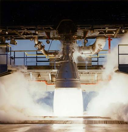
The Main Engine System consists of two Aerojet AJ-26-62 engines. These are modified NK-33 engines that are being converted by Aerojet, importing the Russian engines and adding US electronics, making modifications to the fuel systems, modifying the engine for proper gimbaling control and removing engine harnesses. NK-33 engines were originally built for the massive Soviet N1 Moon Rocket in the 1960s and 70s and have since been in storage, not being used on any launcher.
The engine is a regeneratively cooled staged combustion engine with oxygen-rich preburners to drive the turbopumps. NK-33 provides a maximum sea level thrust of 1,630 Kilonewtons with length of 3.7 meters, an engine diameter of 2 meters and dry weight of 1,235kg. The engine can lift 137 times its weight and provides a vacuum impulse of 331s. Maximum vacuum thrust is 1,815kN. AJ-26 can be throttled from 56 to 108% of rated performance. The two AJ-26 engines of Antares are mounted on a thrust frame and each engine is equipped with independent Thrust Vector Control Systems for vehicle control during ascent. Engine gimbaling is controlled by a Moog hydraulic TVC system.
The two engines are fed by two separate LOX/RP-1 feed systems and have independent electrical hardware. The propellant inlets of the two engines are flexible to allow the engines to move relative to the core structure for Thrust Vector Control. The engine controllers are built by Orbital, but also incorporate engine sensors and propellant utilization systems provided by Yuzhnoye. Also part of the MES is the aft bay closure and the heat shield thermal blanket that protects aft bay components from the heat generated by the main engines.
At liftoff, the two engines generate a total thrust of 332,400 Kilograms. The first stage has a burn time of 235 seconds.
Second Stage

| Type | Castor 30A |
| Length | 3.51m |
| Diameter | 2.34m |
| Dry Mass | 1,220kg |
| Casing Mass | 408kg |
| Ignition, Nozzle, TVC | 340kg |
| Propellant Mass | 12,815kg |
| Launch Mass | 14,035kg |
| Propellant | HTPB H8299 |
| Avg. Thrust | 259kN |
| Max Thrust | 393kN |
| Chamber Pressure | 53Bar |
| Specific Impulse | 301s |
| Nozzle Diameter | 1.21m |
| Expansion Ratio | 65 |
| Burn Time | 136s |
| Vehicle Control | Electromechanical TVC |
| Stage Separation | Non-contaminating frangible ring |
| Attitude control | Cold Gas ACS |
The second stage of the Antares launch vehicle is a solid rocket motor built by Alliant Techsystems, ATK. The first two mission of Antares, the Demo Flight and the Orb-D1 Demonstration Flight to ISS, will use a Castor 30A upper stage while the next two flights will feature the upgraded Castor 30B, flying on Orb-1 and Orb-2. Subsequent missions will use the stretched Castor XL to increase payload capability and allow an upgraded version of the Cygnus to carry more cargo to ISS.
Castor 30A
The Castor 30 solid rocket motor is based on ATK’s Castor 120 which is a derivative of the first stage motor of the Peacekeeper missile that was in service from 1986 to 2005. Castor 120 was used on Lockheed Martin’s Athena launch vehicles.
Castor 30A is 2.34 meters in diameter and 3.51 meters long. It has an empty weight of 1,220 Kilograms and can hold 12,815 Kilograms of propellant. The solid rocket motor uses a 408-Kilogram composite graphite/epoxy wound case.
Castor uses HTPB bound solid propellant. It is optimized for operation in vacuum conditions with an average thrust of 259 Kilonewtons, peaking up to 393 Kilonewtons. The second stage provides a specific impulse of 301 seconds. Castor 30A burns for 136 seconds. Ignition is accomplished with an IVB Ignitor. A flex seal design at the throat of the SRM allows nozzle motion during flight for Thrust Vector Control. The nozzle can be gimbaled as part of a Electromechanical Thrust Vector Control System. A 65:1 throat-to-exit-plane-ratio model provides the second stage performance for the initial Antares missions ahead of second stage upgrades.
Castor 30B
| Type | Castor 30B |
| Length | 4.17m |
| Diameter | 2.34m |
| Propellant Mass | 12,887kg |
| Launch Mass | 13,970kg |
| Propellant | HTPB H8299 |
| Avg. Thrust | 293.4kN |
| Max Thrust | 396.3kN |
| Chamber Pressure | 53Bar |
| Specific Impulse | ~304s |
| Nozzle Diameter | 1.63m |
| Expansion Ratio | 76 |
| Burn Time | 127s |
| Vehicle Control | Electromechanical TVC |
| Stage Separation | Non-contaminating frangible ring |
| Attitude control | Cold Gas ACS |
The Castor 30B rocket motor is a higher-performance version of the Castor 30A with an increase in Isp of under 5 seconds. Its overall length is 4.17 meters and it has a diameter of 2.34 meters. The motor features and extended nozzle with a 76:1 expansion ratio and a diameter of 1.63 meters. The 30B version provides an average thrust of 293.4 Kilonewtons and a maximum thrust of 396.3 Kilonewtons. Castor 30B has a liftoff weight of 13,970 Kilograms and burns for 127 seconds.
Castor 30 XL
| Type | Castor 30 XL |
| Length | 5.99m |
| Diameter | 2.36m |
| Launch Mass | ~26,300kg |
| Propellant | HTPB H8299 |
| Nozzle Length | 2.4m |
| Expansion Ratio | 56 |
| Burn Time | 156s |
| Vehicle Control | Electromechanical TVC |
| Stage Separation | Non-contaminating frangible ring |
| Attitude Control | Cold Gas ACS |
The Castor 30 XL is a stretched version of the Castor 30A solid rocket motor. It also uses a composite graphite/epoxy wound case and HTPB bound propellant.
Castor 30 XL is 2.34 meters in diameter and 5.99 meters long. It has a liftoff mass of about 26,300 Kilograms. The stage delivers an average thrust of over 300kN peaking at 395kN.
Castor 30 XL uses a 2.4-meter long nozzle with a high expansion ratio of 56:1 and submerged design. A dual density exit cone improves performance for operation at high altitudes. The nozzle design features a number of changes to the Castor 30A nozzle such as a modified Propulsion Application Program flex bearing with a 3.5-degree maximum design vector angle. The Castor 30 XL also uses an Electromechanical Thrust Vector Control System that is identical to that of Castor 30A.
Stage 2 Avionics & Guidance System
The Antares avionics module is based on Orbital’s Modular Avionics Control Hardware (MACH) that will provide power transfer, data acquisition, booster interfaces, and ordnance initiation. Most avionics are located in the avionics ring mounted on the second stage. Antares uses a three-axis autopilot that utilizes Proportional-Integral-Derivative control. The first stage flies a pre-programmed attitude profile based on trajectory design and optimization while the second stage adjusts its flight profile dynamically to achieve a pre-programmed set of orbital parameters. It uses energy management to place the vehicle into its target orbit.
Second Stage Attitude Control System
During the second stage burn, a combination of TVC and ACS is used. Antares features a three-axis cold gas attitude control system on its second stage to provide orientation capability during coast phases, for spacecraft separation and subsequent collision avoidance maneuvers.
Optional Third Stage
| Type | Star 48BV |
| Launch Mass | 2,164.5kg |
| Diameter | 1.24m |
| Length | 2.08m |
| Propellant | TP-H-3340 |
| Propellant Mass | 2,010.0kg |
| Casing Mass | 58.3kg |
| Case Material | Titanium |
| Nozzle Mass | 52.6kg |
| Avg Thrust | 68.6kN |
| Max Thrust | 77.8kN |
| Isp | 288s |
| Throat Diameter | 0.1011m |
| Nozzle Diameter | 0.7475m |
| Chamber Pressure | 39.9bar (Avg) – 42.6bar (Max) |
| Expansion Ratio | 54.8 |
| Burn Time | 84.1s |
| Ignition Delay | 0.100s |
| Attitude Control | TVC +/-4° |
Antares can fly with a third stage to increase payload capability and provide accurate insertion capabilities for high-energy insertions.
.
ATK Star 48BV
The ATK Star 48BV is a solid-propellant upper stage that uses the flight proven Star 48B and adds Thrust Vector Capability (V). Star 48 was introduced in 1982 and has been used on a variety of spacecraft. Star 48B was spin stabilized and had smaller a performance than the TVC capable version.
The upper stage features a 1.24-meter diameter titanium casing holding a total of 2,010 Kilograms of solid propellant. It is 2.08 meters in length and has a launch mass of 2,165 Kilograms. It operates at an average thrust of 68.6 Kilonewtons with peak thrust reaching 77.8kN.
Star-48BV features the longer of two available nozzles for the conventional Star 48. The upper stage features an electromechanically actuated flexseal nozzle Thrust Vector Control System with a maximum nozzle gimbal of four degrees. Star-48 burns for 84 seconds and is suitable for payloads that are inserted into high-energy trajectories.
.
Star-48BV Upper Stage
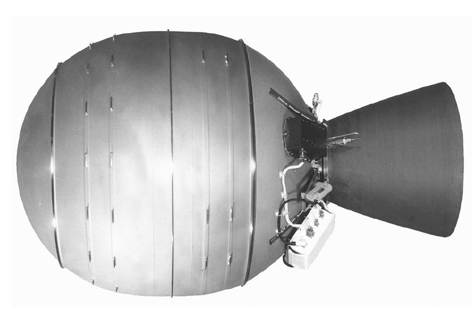
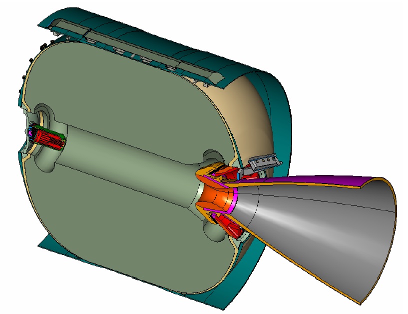
Bi-Propellant Third Stage
| Type | BTS |
| Fuel | Monomethylhydrazine |
| Oxidizer | Nitrogen Tretroxide |
| Fuel Mass | 358kg |
| Oxidizer Mass | 322kg |
| Propulsion | 3 x BT-4 |
| BT-4 Thrust | 450N |
| Total Thrust | 1,350N |
| Engine Mass | 4kg |
| Engine Length | 0.65m |
The Bi-Propellant Third Stage, BTS, is provided by Orbital Sciences and is based on Orbital’s GEOStar satellite bus that is used for Geostationary Satellites. The Upper Stage features a Helium-regulated bi-propellant system with Monomethylhydrazine fuel and Nitrogen Tetroxide oxidizer.
The propellants are stored in spherical tanks. A total of 358 Kilograms of MMH and 322 Kilograms of NTO can be carried by the vehicle. The propulsion system consists of three IHI BT-4 engines. BT-4 was developed by IHI Aerospace, Japan, and has a dry mass of 4 kilograms and a length of 0.65 meters. The engine provides 450 Newtons of Thrust.
The BTS can perform precise insertions and multiple engine burns for orbit circularization. Sun Synchronous Missions of Antares would typically use this upper stage.
Payload Fairing
| Diameter | 3.94m |
| Length | 9.87m |
| Mass | 970kg |
| Separation | Ordnance, Frangible Joints, Pistons |
| Construction | Aluminum Honeycomb |
| Graphite/Epoxy Sheets |
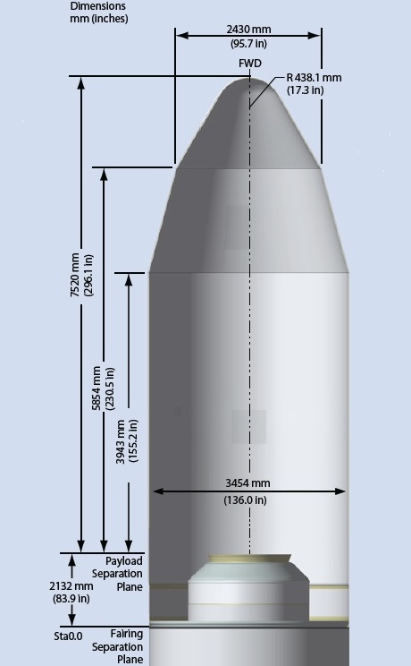
The Payload Fairing is positioned on top of the launch vehicle and its integrated Payload. It protects the spacecraft against aerodynamic, thermal and acoustic environments that the vehicle experiences during atmospheric flight.
When the launcher has left the atmosphere, the fairing is jettisoned by pyrotechnical initiated systems. Separating the fairing as early as possible increases launcher performance.
Antares jettisons its fairing during the Coast Phase between the first and second stage burn during a typical LEO Flight.
The fairing is 3.94 meters in diameter and 9.87 meters long. It consists of two composite shell halves, a low-shock frangible rail and ring separation system, and an actuator/hinge fairing jettison system.
The fairing structure is a aluminum honeycomb core covered by layers of graphic epoxy composite. The two fairing halves are joined by a frangible rail joint and the PLF is connected to the second stage using a ring-shaped frangible joint.
Ordnances and a clean-separation frangible joint with a confined sealed stainless steel tube is used to fracture aluminum extrusions on the ring and rail.
Disconnecting the ring and rail allows each half of the fairing to rotate on hinges installed on the second stage. A cold gas generation system is utilized to drive pistons that force the fairing halves to open..
Payload Adapters
Payload Adapters interface with the launch vehicle and the payload and are the only attachment point of the payload on the Launcher. They provide equipment needed for spacecraft separation and connections for communications between the Upper Stage and the Payload.
Orbital Sciences offers a number standard payload adapters to install spacecraft on the Antares launch vehicle. Payload Adapters are provided by RUAG Space and include the 1194VS, 1666 and 937 payload systems that provide accommodations for a number of spacecraft and feature low-shock separation techniques.
Antares – Versions and Performance
| Version | Configuration | ||
| Stage 1 | Stage 2 | Stage 3 | |
| 110 | 2 x AJ-26-62 | Castor 30A | – |
| 120 | 2 x AJ-26-62 | Castor 30B | – |
| 121 | 2 x AJ-26-62 | Castor 30B | BTS |
| 122 | 2 x AJ-26-62 | Castor 30B | Star-48BV |
| 130 | 2 x AJ-26-62 | Castor XL | – |
| 131 | 2 x AJ-26-62 | Castor XL | BTS |
| 132 | 2 x AJ-26-62 | Castor XL | Star-48BV |
| Version | Performance | |||
| LEO | SSO | GTO | Planetary | |
| 110 | ||||
| 120 | 4,600kg | 1,500kg | ||
| 121 | 4,750kg | 2,900kg | ||
| 122 | 900kg | |||
| 130 | 5,100kg | |||
| 131 | 5,600kg | 3,600kg | ||
| 132 | 1,800kg | 1,100kg | ||
.
Numbering System:
First Digit: Always 1 – Liquid-Fueled First Stage
Second Digit: 1 – Castor 30A Second Stage; 2 – Castor 30B Second Stage; 3 – Castor 30 XL Second Stage
Third Digit: 0 – No third Stage; 1 – Bi-Propellant Third Stage; 2 – Star-48BV Third Stage
Antares LEO Flight Profile
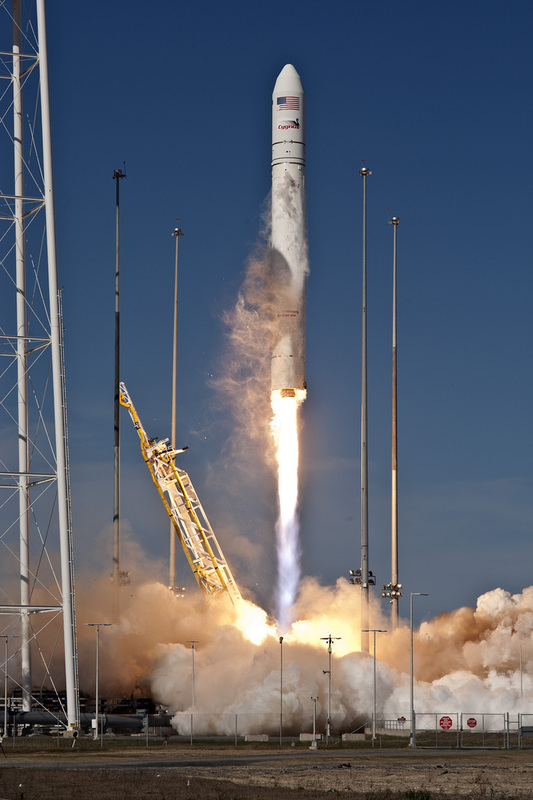
Antares lifts off from its launch pad two seconds after the AJ-26 engines of the first stage are ignited to allow some time for them to achieve full thrust and monitor their ignition performance. After a short vertical ascent, Antares performs a roll & pitch maneuver to align itself with its pre-planned ascent trajectory.
The first stage burns for 235 seconds and separates after a brief, 5-second post-burn coast. Stage 1 separation occurs at an altitude of 109 Kilometers and a velocity of 4,547m/s. At that point, the stack enters a 100-second coast period to get close to apogee for the second stage burn. After 100 seconds of coasting, the Payload Fairing is jettisoned at an altitude of 184 Kilometers. Ten seconds later, the second stage begins its engine burn for orbital insertion and circularization. Stage 2 shutdown occurs about 471 seconds into the flight at an altitude of 205 Kilometers and a velocity of 7,521m/s. Payload separation occurs after 120 seconds of maneuvering by the second stage attitude control system. The typical Cygnus insertion orbit is 275 by 250 Kilometers at an inclination of 51.66 degrees.
