Proton-M/Block DM-03 – Launch Vehicle
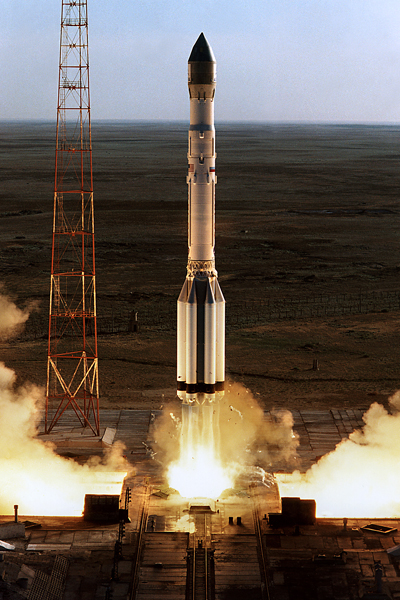
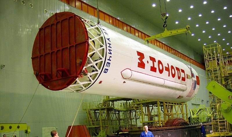
The Proton Rocket Family is one of the most successful heavy-lift boosters in the history of space flight. Being designated UR-500, the Rocket started out as a Super Intercontinental Ballistic Missile in the 1960’s. As it was capable of launching a 100-megaton nuclear warhead, Proton was hugely over-sized and became a Space Launcher designed to lift the heaviest payloads to space.
The first Proton Launch was made in 1965. during the first five years of operation, the system experienced dozens of failures before becoming a reliable booster. Over the years, the Proton Family underwent several modifications and re-designs in order to keep the Rocket’s System up to date using modern technology. The early version of the Proton Family was called 8K82 and was equipped with only two stages. Proton-K was the first featuring three stages and an optional upper stage. The Proton-K Launcher was retired in 2012, leaving only the improved version of the Family, Proton-M, active.
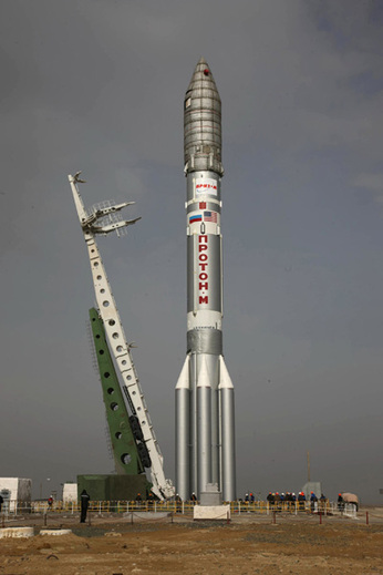
This particular launcher configuration made its first launch in 2001. Proton-M is also a three-stage rocket with the capability to support a upper stage. Block D/DM and Briz-M (English: Breeze-M) Upper Stages are used on top of the Proton to enable the heavy-lift vehicle to deliver its payload to a variety of orbits and trajectories. The Proton Rocket is launched from Sites 81 and 200 of the Baikonur Cosmodrome, Kazakhstan. Khrunichev State Research and Production Space Center is the manufacturer of Proton-M Briz-M. Proton-M Launchers are operated by the Russian Government for official government mission. Also, the Rocket has been made available for commercial launches which are being operated by International Launch Services.
The Proton Family has more than 340 Launches under its belt keeping a success rate of nearly 90%. Notable payloads included modules of the Russian Salyut and Mir Space Stations as well as the Zarya and Zvezda Modules of the International Space Station. Many commercial communication satellites have been orbited using Proton-M Rockets with Briz-M Upper Stages.
Proton-M/Block DM-03 Specifications
| Type | Proton-M |
| Height | 58.2m |
| Diameter | 7.4m |
| Launch Mass | 712,800kg |
| Stages | 3 (+ Optional Upper Stage) |
| Boosters | None |
| Mass to LEO | 22,000kg |
| Mass to GTO – Briz-M | 6,000kg |
| Mass to GSO – Briz-M | 3,500kg |
The Proton-M Vehicle consists of three Stages each equipped with different engines that place the orbital Unit Consisting of Upper Stage and Payload to its desired trajectory in about 9 minutes. Compared to previous Proton versions, Proton-M utilizes light-weight technology as part of an effort to reduce launcher mass to maximize its capability. Also, the avionics of the Proton-M are digital, state of the art systems. Proton-M uses a simple design philosophy to increase reliability and improve flight heritage on proven components.
Overall, Proton-M/Block DM-03 stands 58.2 meters tall with a diameter of 7.4 meters and a launch mass of nearly 713,000 Kilograms. Proton-M can deliver payloads of up to 22,000 Kilograms to Low Earth Orbit. With Block DM-03, the Proton can deliver satellites of 6 metric tons into Geostationary Transfer Orbit. Direct Geosynchronous injection capability is 3.5 tons.
First Stage
| Type | Proton-M Stage 1 |
| Inert Mass | 31,000kg |
| Diameter | 7.4 m |
| Length | 21.18 m |
| Structure | Aluminum Alloy (AlMg6) |
| Propellant | Unsymmetrical Dimethylhydrazine |
| Oxidizer | Dinitrogen Tetroxide |
| Propellant Mass | 419,400kg |
| Guidance | From second Stage |
| Propulsion | 6 x RD-275M |
| RD-275M Thrust SL | 1,670 kN |
| RD-275M Thrust Vac | 1,830 kN |
| Specific Impulse (SL) | 288 sec |
| Specific Impulse (Vac) | 315.8 sec |
| Total SL Thrust | 10,020 kN |
| Total Vac Thrust | 10,980 kN |
| Engine Length | 3.00 m |
| Engine Diameter | 1.50 m |
| Engine Dry Weight | 1,120 kg |
| Throat Diameter | 279.7 mm |
| Combustion Chamber | 430.0 mm |
| Chamber Pressure | 165 bar |
| Ox. To Fuel Ratio | 2.67 |
| Expansion Ratio | 26.4 |
| Chamber/Nozzle Length | 2.23 m |
| Oxidizer Flowrate | 392.3 kg/sec |
| Fuel Flowrate | 146.9 kg/sec |
| Burn Time | 119.6 sec |
| Tank Pressurization | Gas Generator (F) / Mixer (O) |
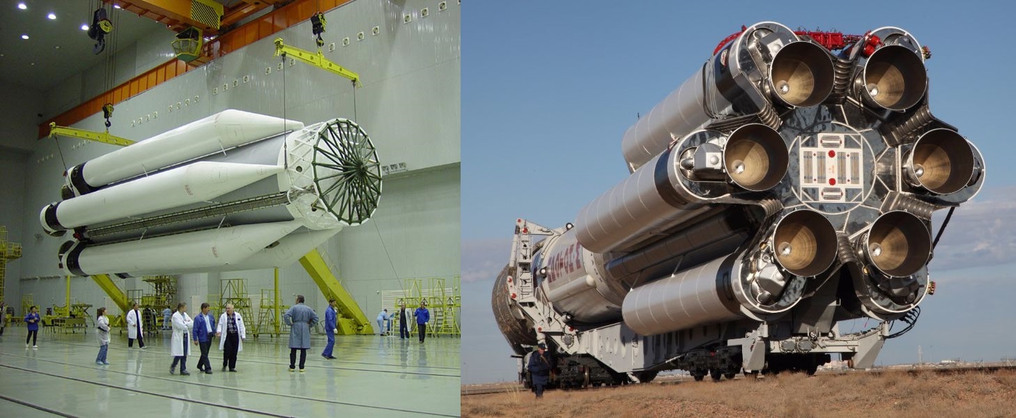
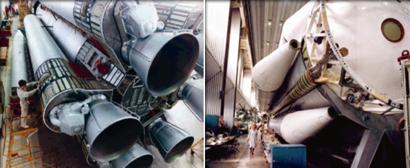
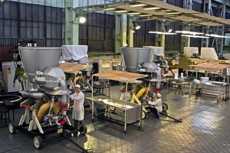
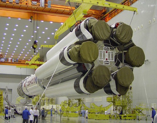
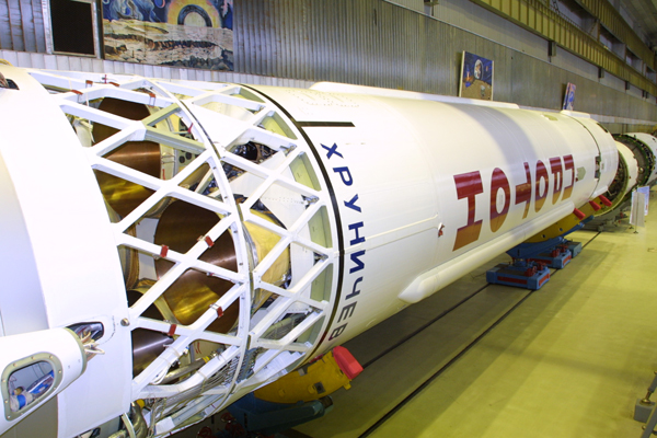
The first stage of the Proton Proton-M, in its overall architecture, has been in operation since the first Proton launch in 1965 though has undergone modification over the years to be fitted with more-powerful engines and reduce its dry mass. It stands 21.18 meters tall and measures 7.4 in diameter, comprising a central oxidizer tank and six strap-on fuel tanks that give Proton its characteristic appearance.
The central oxidizer tank is 4.1 meters in diameter and each of the six external fuel tanks measures 1.6 meters in diameter and 19.86 meters in length with a tapered section on top to create an aerodynamic shape. The six fuel tanks resemble the appearance of strap-on boosters used on other rocket types but do not in fact separate from the first stage.
This sectioned design choice was made at the inception of Proton since the 4.1-meter core diameter was the largest possible for rail-transport to the Baikonur Cosmodrome. The fuel tanks are integrated with the core oxidizer tank at the launch site after separate delivery.
The fuel tanks build a critical structural element of the Proton launch vehicle as each hosts one of the six first stage main engines and is responsible for transferring loads to the central structure. There is no propellant cross feed between the six fuel tanks which deplete evenly as the engines burn and oxidizer is fed to the engines from the central core (the even depletion of all six fuel tanks is ensured by an RKS control system optimizing the mixture delivered to each engine to ensure an even burn).
The strap-on tanks attach to the core stage via five joints, two rigid joints at the base of the strap-on and three flexible joints that allow for some flexibility.
Proton’s first stage has dry mass of less than 31 metric tons and holds over 419 metric tons of Unsymmetrical Dimethylhydrazine fuel and Dinitrogen Tetroxide oxidizer, fed to six RD-275M engines.
One element of Proton’s evolution from the Proton-K (flown between 1967 to 2012) to the Proton-M (in service since 2001) and the Proton-M Phase upgrades was the reduction of the rocket’s dry mass through the use of lightweight composite material on the upper stage and modern-day milling techniques to reduce the mass of the vehicle’s tankage. As a result, Proton lost over 400 kg of weigh on its first stage alone.
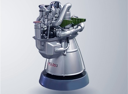
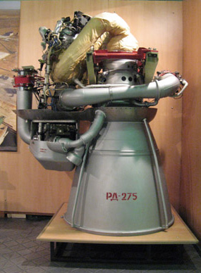
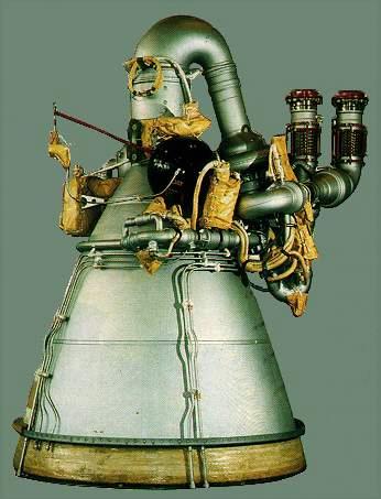
Built by NPO Energomash, the RD-275M – also known as RD-276, is an improved version of Proton’s original, Glushko-designed RD-253 engine and classed as the most-powerful single-chamber, hypergolic-fueled engine built in Russia. RD-253 (1,470kN SL thrust) served on the first four Proton missions in 1965/66 that used the two-stage configuration and it continued to power the vehicle as it upgraded to the three-stage Proton-K.
An initial performance enhancement on the RD-253 was realized by increasing the propellant mass flow by slight modifications of the propellant flow control valves after it had become clear that most structural margins on the engine would permit a 7.7% thrust increase with structural reinforcements made only on the gas generator and combustion chamber. This enhancement first flew as a mission-unique feature on the 1986 and 1987 launches of the Core and Kvant Modules of the Mir Space Station (RD-253F).
Qualification of this engine version, known under the operational designation RD-275 (1,590kN SL) was completed between 1987 and 1993 and the engine began flying as a standard feature on Proton-K in 1995. RD-253 was retired in 1997 after supporting 250 Proton launches and the introduction of RD-275 provided a 600-Kilogram increase in Proton’s GEO capacity.
The second round of improvements on the RD-275 engine started in 2001 to obtain another thrust boost of 5.2% by further increasing the engine’s operating pressure by 8.3 bar. Testing of the RD-275M engine wrapped up in 2005 and it began operations on Proton-M in 2007, yielding another 150-Kilogram increase in GEO performance.
Like many Russian engine developments, the RD-275M operates an oxidizer-rich, staged combustion cycle which, compared to fuel-rich alternatives, offers higher performance but creates a more-challenging environment due to the temperature and corrosive properties of the oxidizer-rich mixture in the engine. Additional performance is gained through the use of a closed cycle in which the entire propellant flow into the engine is brought to combustion and no low-pressure turbine exhaust is dumped overboard.
The RD-275M engine stands 3.05 meters tall and is 1.50 meters in diameter with a dry mass of 1,070 kilograms and a flooded mass of around 1,250 kg. It delivers a sea level thrust of 1,670 Kilonewtons, climbing to 1,830 kN in vacuum with corresponding specific impulses of 288 and 315.8 seconds. The engine operates at a chamber pressure of 165 bar, feeding a 26.2-expanded nozzle.
RD-275M employs a single, gas-generator-driven turbine for powering the engine’s turbopumps – a single-stage oxidizer pump and a two-stage fuel pump, both arranged on a single axis but employing different drive shafts connected with a spring assembly to transfer the torque from the oxidizer pump shaft to the two-stage fuel pump. The entire oxidizer flow passing through the turbopump is injected into the gas generator while the output from the first stage of the fuel pump is divided in two with one portion flowing into the regenerative cooling cycle and the other directed into the second-stage fuel pump which creates the required pressure and flow rate for the gas generator.
The gas generator operates at an oxidizer-to-fuel ratio of 21.5 to create a turbine power in excess of 26,000 horsepower to drive the two turbopumps at over 14,000 RPM for the oxidizer. The 785-Kelvin oxidizer-rich gas from the turbine is routed into the combustion chamber where it is combined with the fuel flow from the chamber & nozzle cooling cycle to be fully combusted at a mixture ratio of 2.67.
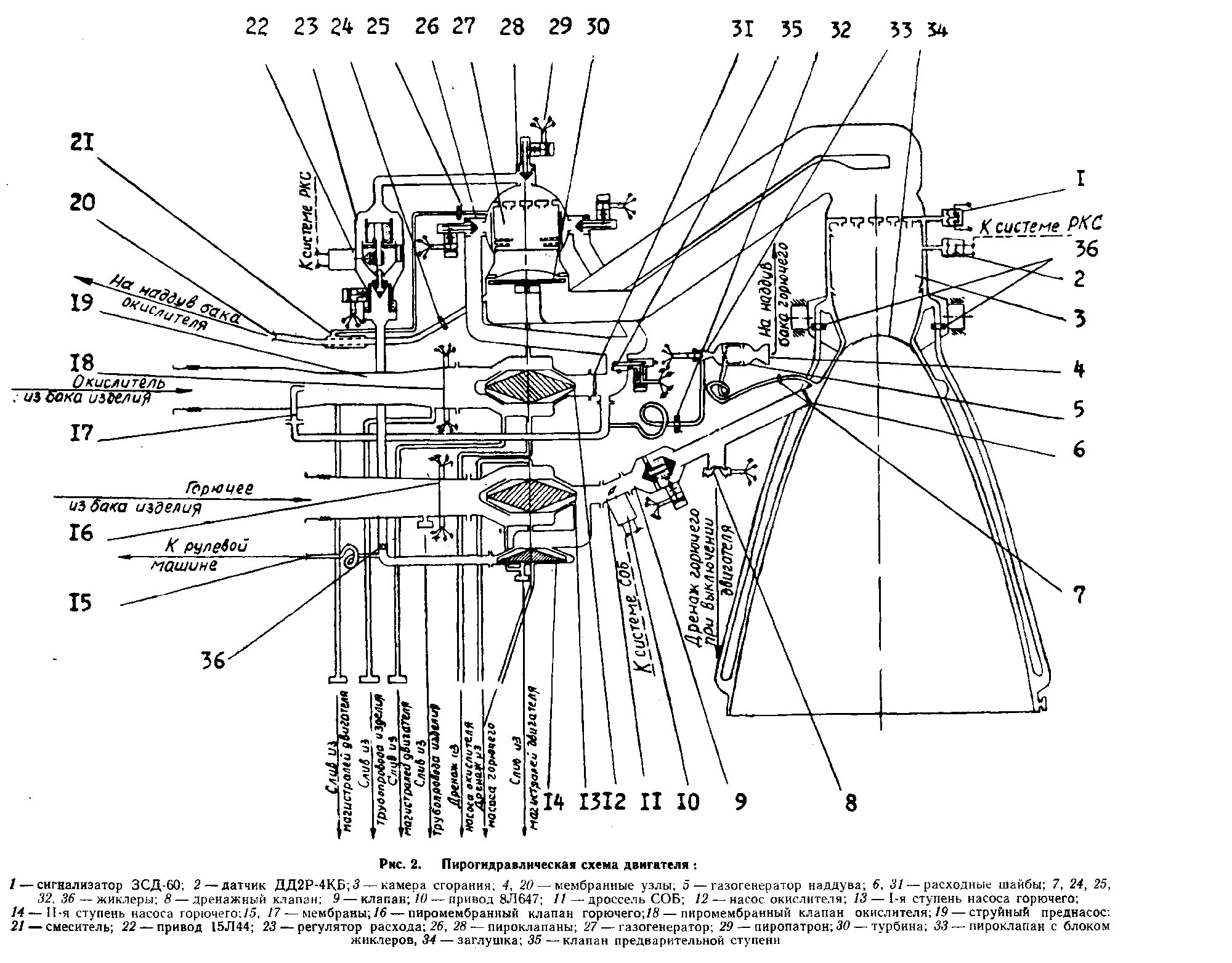
Engine start is a carefully controlled process that involves the sequential opening of a series of engine valves to put the engine into steady-state operation. Because self-igniting propellants are used, no igniters are necessary, but particular attention has to be paid to avoid bleed-in of fuel into the oxidizer system and vice versa within the turbopump assembly.
Pyrotechnic valves (employing a pyrotechnic cutting mechanism to cut open a membrane) fire 0.7 seconds after the engine ignition command is given to allow the engine plumbing to fill with propellant components under the hydrostatic pressure created by the propellant tanks. This allows propellant to flow through the pumps and into the gas-generator where the two components are mixed through 85 fuel and 288 oxidizer injector nozzles and combust upon contact to begin driving the turbine. The gas generator operates in a two-zone scheme with 70% of the oxidizer flow passing through the injectors while the rest is routed through heat exchangers in the GG mantle and then being injected around the flow of heated product gas to provide a thermal boundary between the hot zone where combustion occurs and the GG housing.
Once combustion begins in the main chamber, a membrane protecting the injectors /chamber during storage on the ground is broken and ejected from the nozzle.
During the ignition phase, fuel flow to the gas generator is limited by a dedicated flow regulator. As pressures increase, membranes are broken to allow propellants into the tank pressurization and gimbal systems to prepare them for steady-state operation. Around 1.8 seconds after ignition command, the engine controller commands the gas generator fuel flow regulator to fully open to allow the turbine to spin up to flight speed.
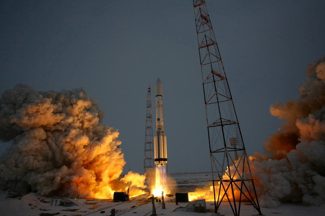
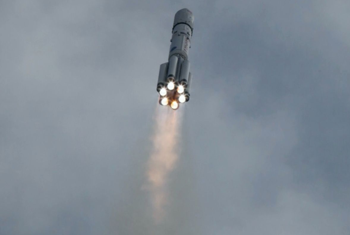
Proton lifts off once engine thrust exceeds the rocket’s mass; there is no hold-down system. The engines reach their full thrust level shortly after liftoff and are kept at operational conditions through a feedback loop that employs twofold sensing system: a pressure sensor in the main combustion chamber provides feedback on the operation of the engine (to be kept within an operational pressure band) while the rocket’s guidance system tracks the vehicle’s speed vs. the prediction to fine tune the thrust level according to the flight trajectory.
This regulation is achieved by the fuel flow regulator to the gas generator which speeds up/slows down the turbopumps by means of fuel flow into the gas generator based on commands from the engine controller.
The mixture ratio of fuel and oxidizer is controlled by flow restrictors in the main propellant lines after the turbopumps and an additional fuel trim system after the first-stage pump is employed for fine control to ensure the tanks empty at the same rate by controlling the fuel flow into the main combustion chamber.
Shutdown of the engine is also a multi-stage process to prevent pressure hammering from destroying the engine. The first step is the closure of the gas generator fuel inlet pyrovalve and the oxidizer tank pressurization pyrovalve which will cause the gas generator to be starved of fuel to stop the combustion process while oxidizer still flows through from the residual tank pressurization and pump rotation. Fuel is also still allowed into the main combustion chamber through the regenerative cooling loop.
The second shutdown stage is accomplished over 0.2 seconds by closing oxidizer valves to the gas generator and the main fuel valve to the combustion chamber. This ends propellant flow through the gas generator, main chamber and mixers for tank pressurization and gimbaling. A propellant dump valve then opens between regen cooling cycle and the cutoff valve to allow fuel still in the cooling system to escape at low pressure to avoid residual thrust on the engine (the dump valve remains closed in case of an aborted ignition on the ground, the rest of the shutdown process remains the same).
The combustion chamber and nozzle of the RD-275M engine stand 2.24 meters tall and weigh around 435 Kilograms. The combustion chamber is 430 millimeters in diameter and closes into an engine throat diameter of 279.7 millimeters which then broadens to a nozzle exit diameter of 1.43 meters.
A jet pre-pump before the oxidizer inlet provides an increase in static pressure at the inlet to ensure the engine can operate at low oxidizer tank pressures without cavitation in the main pump. Tank pressurization is accomplished with a gas generator on the fuel side and a mixing unit on the oxidizer side.

The gas generator is fed from a tapoff line on the oxidizer turbopump outlet and the fuel line from the inlet of the generative cooling cycle; flow restrictors act as regulation devices to achieve a simplified architecture. It operates at a mixture ratio of 0.06 and, like the main GG, employs a two-zone scheme where all of the oxidizer inflow and a third of the fuel flow is brought to combustion while the rest of the fuel is used to create a cooling film on the inside of the enclosure. The gas generator delivers an outlet pressure of 25 bar which is fed to the fuel tank the respective engine is attached to.
The oxidizer pressurization mixer is fed with oxidizer-rich tapoff gas from the turbine which is mixed with oxidizer flow from the gas generator inlet to cool the gas. It delivers an outlet pressure of 35 bar fed through a pressurization line to the central oxidizer tank which is kept at pressure by all six engines.
Proton uses a one-degree of freedom thrust vector control system on its first stage. Each of the six engines can only move +/-7 degrees in one direction, tangentially to the circular engine cluster – enabling three-axis control through the collective gimbaling inputs of the engines. The one-axis gimbaling system is driven by a hydraulic system supplied by a tapoff line from the second-stage fuel pump.
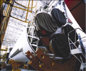
A crude form of thrust vector control employed during the initial roll maneuver after liftoff is differential thrust vector control achieved by reducing thrust on one engine by limiting propellant flow into its combustion chamber (visible as the dim engine near the six-o-clock position in the image).
The first stage of the Proton-M rocket typically fires between 119.6 to 123.2 seconds depending on the specific mission profile. Per Proton’s typical flight profile, the first stage accelerates the vehicle to a speed of 1.72 Kilometers per second and lifts it to an altitude of 42 Kilometers, impacting around 310 Kilometers from the launch site. To lessen the environmental impact of the rocket’s leftover propellant, modifications were made to cut in half the propellant residuals present at shutdown which are then vented overboard to disperse and decompose as a result of atmospheric interaction.
Second Stage
| Type | Modified Proton-M Stage 2 |
| Inert Mass | 11,715 kg |
| Diameter | 4.1 m |
| Length | 17.05 m (w/ Interstage) |
| Structure | Aluminum Alloy |
| Propellant | Unsymmetrical Dimethylhydrazine |
| Oxidizer | Dinitrogen Tetroxide |
| Propellant Mass | 156,113 kg |
| Guidance | Inertial |
| Propulsion | 3 x RD-0210, 1 x RD-0211 |
| RD-0210 Thrust Vac | 582 kN |
| Specific Impulse (Vac) | 326.5 sec |
| Total Vac Thrust | 2,328 kN |
| Engine Length | 2.33 m |
| Engine Diameter | 1.47 m |
| Engine Dry Weight | 566 kg |
| Throat Diameter | 163 mm |
| Combustion Chamber | 276 mm |
| Chamber Pressure | 147 bar |
| Ox. To Fuel Ratio | 2.6 |
| Expansion Ratio | 28.5 |
| Chamber/Nozzle Length | 1.67 m |
| Oxidizer Flowrate | 131.3 kg/sec |
| Fuel Flowrate | 50.5 kg/sec |
| Burn Time | 210.8 sec |
| Tank Pressurization | From RD-0211 Gas Generators |
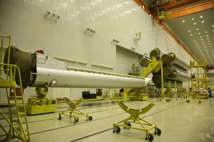
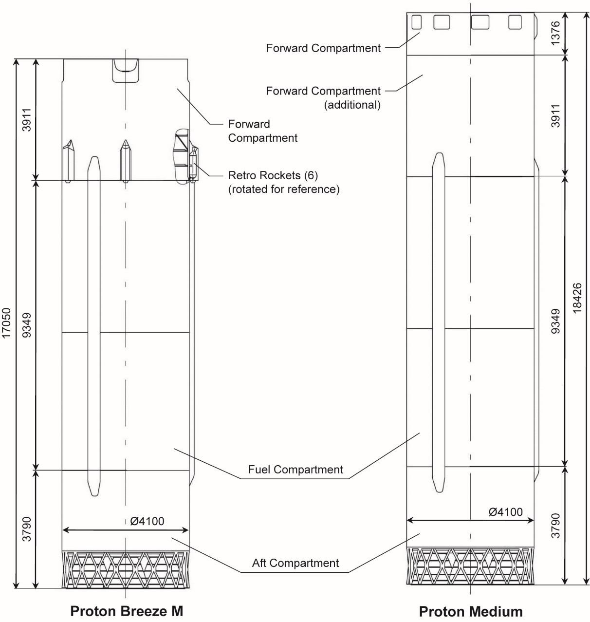
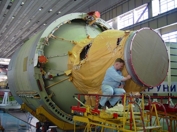
Unlike the first stage, Proton’s second stage uses the conventional cylindrical design with the fuel and oxidizer tanks mounted in a stacked configuration within the stage. Its structure consists of an aft compartment housing the engines, a fuel compartment holding the propellant components and a forward compartment / forward compartment extension building the interface with the Ascent Unit.
The Proton second stage shares the first stage’s 4.1-meter diameter and stands 18.43 meters tall (with interstage, 1.4 m taller than Proton-M’s second stage). It has a dry mass around 12 metric tons and holds 156,113 Kilograms of Unsymmetrical Dimethylhydrazine fuel and Dinitrogen Tetroxide oxidizer. The oxidizer tank is located above the fuel tank and the oxidizer line to the engines runs through the center of the UDMH tank. A common bulkhead is used between the tanks as a mass and space-saving measure to optimally use the internal volume of the second stage.
The aft compartment of the second stage stands 3.79 meters tall and hosts the four second stage engines and the upper portion of the Stage 1-2 interstage structure. In addition to the engines and all their associated equipment, the aft section also houses six angular rate sensors that act as the primary attitude determination device on the second stage. The tank section of the second stage is 9.05 meters tall.
On Proton-M, the Stage 2 Interstage Adapter, standing 3.91 meters tall, is fitted with six solid-fueled retrorockets to push the stage away from the third stage to assist in the hot-staging sequence.
Another requirement arising from the elimination of the Proton third stage was moving the Booster Avionics Bay, situated atop the stage, to the second stage to provide guidance for the two lower stages. The various boxes comprising the avionics assembly were thus moved to the forward compartment extension of the second stage.
However, this was not responsible for the lengthening of the interstage compartment which was driven by creating a vehicle height that would require the least modifications on the existing ground infrastructure at Baikonur with respect to the service tower and transporter-erector.
The second stage of the Proton rocket is powered by three RD-0210 and one RD-0211 engines which are identical in their propulsive function, generating 582 Kilonewtons of vacuum thrust, with the major difference being that RD-0211 is fitted with gas generators to provide pressurization gas to the tanks.
These engines, like those of the first stage, start out at the very dawn of the space age and have undergone significant upgrades since. Their development began in 1961 as RD-0203/0204 for the first stage of the UR-200 ballistic missile with a performance target of 500 kN per engine (SL). When Proton (back then known as UR-500) began development on the drawing board, its first stage was to host four RD-253 main engines and four RD-0203 engines for steering & additional thrust.
UR-200 was tested between 1963 and 65 and Proton’s design was revised in the same period – eliminating the engine from the first stage and moving it to the second stage – requiring an air-startable version to be developed. It differed from the original design mainly in the expansion of the nozzle to optimize the engines for operation in the tenuous layers of the atmosphere from 50 Kilometers up.
The RD-0208/0209 version of the engine, developed between 1962 and 66, operated at a chamber pressure of 147 bar and generated a vacuum thrust of 570 Kilonewtons. The upgrade was primarily focused on adding a membrane valve, cutoff and bypass into the fuel system to prevent the turbopumps from excessively spinning and ensure the gas generator ignition must occur before propellant components meet in the combustion chamber. A slight performance increase was achieved through the use of more effective turbopump injectors.
Almost concurrently with their development, KBKhA was also developing an upgraded version (1962-67) that was to power the Proton-K rocket and had the overall objective of extracting additional performance but mainly to increase the reliability of the engine through reinforcements of critical components like gas generator, turbine and combustion chamber. Operation on Proton-K also required the engines to be certified for up to 70 seconds of additional burn time.
Improvements of the RD-0210/0211 upgrade included the optimization of the oxidizer gas generator injectors to reduce vibration; a zirconium dioxide thermal protection coating was introduced on the internal surface of the combustion chamber. Reliability was also improved through strengthening of testing procedures – increasing the production batch size from five to six so that two of the engines could be test fired while four were cleared for integration on the launch vehicle; an additional step was testing the pressure integrity of flight engines through helium pressure decay checks.
The RD-0210/0211 engines have been flying on Proton since March 1967 and, over the years, have undergone some modernization with respect to manufacturing processes and materials used in weld and solder joints. The engine stands 2.33 meters tall, is 1.47 meters in diameter and weighs 566 Kilograms; it delivers a vacuum thrust of 582 Kilonewtons at a specific impulse of 326.5 seconds.
The RD-0210/0211 engines are strikingly similar to the RD-253/275 engines used on the first stage – sharing the same closed combustion cycle with oxygen-rich gas generator, single-shaft turbopump, regenerative cooling cycle for the chamber and nozzle (fuel), two-zone gas generator (oxidizer as coolant), and dual-feedback systems for engine control (fuel flow variation to the GG to keep engine pressures & temperature within bands; fuel flow variation through the regen cycle to control the even consumption of oxidizer and fuel). Changes from the RD-253 cycle lie in the use of boost pumps for both propellant components to prevent cavitation at low tank pressures
Another difference to the first stage engines is the ignition sequence of the RD-0210/0211 engines. Starting out as a first stage engine, they relied on a one-second long nitrogen purge prior to the ignition trigger followed by the injection of pressurized gas (air or nitrogen) from a ground system to get the turbine spinning and open the main fuel and oxidizer valves. To achieve an air-start capability outside the dense atmosphere, the engines have to bring the initial burst of gas pressure with them in the form of a small spherical gas tank.
All four engines of the second stage employ an electro-hydraulic, two-axis gimbal system, capable of moving each nozzle by 3.25 degrees to support three-axis control during the second stage flight phase.
Per Proton’s typical mission profile, the second stage burns for 210 seconds, separating from the third stage at the 327-second mark into the flight at a speed of 4.45 Kilometers per second and 120 Kilometers in altitude. Debris of the second stage impact 1,985 Kilometers from the launch site.
Third Stage
| Type | Storable Propellant Stage |
| Inert Mass | 4,185kg |
| Diameter | 4.14m |
| Length | 6.5m |
| Propellant | Unsymmetrical Dimethylhydrazine |
| Oxidizer | Dinitrogentetroxide |
| Fuel&Oxidizer Mass | 46,562kg |
| Guidance | Inertial |
| Propulsion | RD-0213 Engine + RD-0214 Vernier |
| RD-0123 Chambers | 1 |
| RD-0213 Thrust Vac | 583kN |
| Engine Diameter | 4.1m |
| Area Ratio | 81.3 |
| Chamber Pressure | 14.7 MPa |
| RD-0214 Chambers | 4 |
| RD-01214 Thrust | 31kN |
| Chamber Pressure | 5.3 MPa |
| Total Thrust | 613.8kN |
| Burn Time | 238sec |
| Vacuum Impulse | 325s |
The third stage of the Proton-M Rocket is the final stage of the actual launch vehicle that delivers the orbital unit to a preliminary orbit or a suborbital trajectory, depending on the mission profile.
This stage also utilizes a conventional design and consumes Nitrogen Tetroxide and Unsymmetrical Dimethylhydrazine a propellants. An RD-0213 engine powers the vehicle providing 583 Kilonewtons of thrust.
This engine is a non-gimbaled version of the RD-0210 engine that is used on the second stage. For vehicle control and additional thrust, an RD-0214 Engine with four gimbaled nozzles is installed on the third stage.
The RD-0214 provides 31 Kilonewtons of thrust for a total 3rd stage thrust 62,600 Kilograms.
The third stage houses the vehicle’s Navigation, Guidance and Control System that operated the vehicle during all aspects of powered flight which is fully automated and does not require commands from ground stations. A triple redundant digital guidance system is used to control the vehicle.
The Control System has been upgraded several times since the Proton-M started operations in 2001. The guidance mode used is cosed-loop. A high-precision three-axis gyro stabilizer provides exact attitude data to the digital flight computer. The avionics system also provides flight termination in case of a major anomaly during ascent.
Block DM-03 Upper Stage
| Type | Upper Stage |
| Diameter | 3.72m |
| Length | 7.10m |
| Inert Mass | 3,500kg |
| Propellant | Kerosene |
| Oxidizer | Liquid Oxygen |
| Fuel&Oxidizer Mass | 18,600kg |
| Guidance | Inertial |
| Propulsion | 1 RD-58M |
| Thrust | 83.4kN |
| Re-Starts | Up to 5 |
| Engine Length | 2.27m |
| Engine Diameter | 1.17m |
| Engine Dry Weight | 300kg |
| Thrust-to-Weight | 37 |
| Burn Time | 770s |
| Specific Impulse | 349s |
| Chamber Pressure | 77.5bar |
| Ox to Fuel Ratio | 2.48 |
| Attitude Control | Two Attitude Control Assemblies |
| Thrust | 4 Thrusters per Assembly |
| Propellant | Hydrazine |
| Oxidizer | Nitrogen Tetroxide |
The Block DM-03 Upper Stage represents a modification of the Block-DM Upper Stage that has first flown in 1974 and has undergone a number of major upgrades and re-designs over the decades. Originally, the Block-D originated in the Soviet Union’s lunar exploration plans. It was planned to serve as upper stage on the N1 Moon Rocket to perform burns during Earth-Moon transit.
Today, Block-D Upper Stages fly in a number of configurations, depending on the type of launch vehicle and the particular payload. Currently, Block DM-2, DM-2M, DM-03 are used on the Proton Rocket. Sea Launch uses modified Block-DM-SL Upper Stages on their Zenit 3SL launcher. On Proton-M, the use of Block-D has significantly decreased as the Briz-M upper stage provides an increased Payload Capability to Geosynchronous Transfer Orbit. Overall, Block-D type upper stages have flown more than 250 missions.
The main difference between Briz-M and Block-D is that Briz-M uses storable propellants while Block-D uses Liquid Oxygen and Kerosene. Because of that, Briz-M is more flexible as it can operate for a longer mission duration. Using LOX, Block-D has the problem of oxygen boil-off during flight which limits its capabilities. Although Block-DM provides a higher performance, the more flexible Briz-M can fly a profile that allows it to increase its Payload Capability to GEO, GTO and GSO missions.
Block DM-03 is a modified version of the Block DM-2 featuring larger propellant tanks that can hold about 25% more propellants. The Upper Stage is built to be as small as possible to leave enough room for large payloads under the Payload Fairing. It has a dry mass of 3,500 Kilograms. Block-DM-03 provides a precise injection capability and can support ascent missions of several hours.
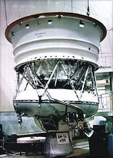
The Upper Stage uses Liquid Oxygen as Oxidizer and Rocket Propellant 1 as Fuel. The Propellants are stored in two tanks that are part of the core module of the Vehicle. The LOX tank has a spherical shape; the kerosene tank is toroidal, inclined to 15 degrees for better fuel extraction. In total, 18,600 Kilograms of Propellants are stored in the Block-DM-03’s Tanks.
The Upper stage is powered by a single RD-58M Main Engine. It provides 83.4 Kilonewtons of Thrust. The engine is a pump-fed engine that provides gimbaling capability. The Main Engine can be started up to 5 Times and has a fully redundant ignition system. Attitude Control during cruise phases is provided by two Attitude Control Thrusters that are also used for ullage burns. Each attitude control engine has four nozzles that are grouped in clusters on either side of the main engine. The Attitude Control System uses Nitrogen Tetroxide and Unsymmetrical Dimethylhydrazine as propellants. All aspects of the Block-DM Mission are controlled by the vehicle’s avionics and pre-flight commands/programs. Block-DM has a passive and active thermal control system to keep all of its systems in operating condition during longer flights. After spacecraft separation, the Upper Stage performs Collision avoidance maneuvers or performs a deorbit maneuver, depending on the flight trajectory.
Payload Fairing
| Diameter | 4.35m |
| Length | 13.31m/15.26m |
| Mass | ~2,000kg |
| Separation | During 3rd Stage Burn |
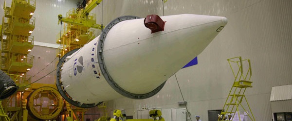
The Payload Fairing is positioned on top of the stacked vehicle and its integrated Payload. It protects the spacecraft against aerodynamic, thermal and acoustic environments that the vehicle experiences during atmospheric flight. When the launcher has left the atmosphere, the fairing is jettisoned by pyrotechnically initiated systems. The fairing is attached to the third stage and the Upper Stage.
Proton-M can be equipped with two different fairing designs. Both are cylindrical in shape, but their overall length and weight varies. Both types of fairing have an inner diameter of 4.35m. The shorter version is 13.31m in length while the large fairing is 15.26m long.
Payload Adapter
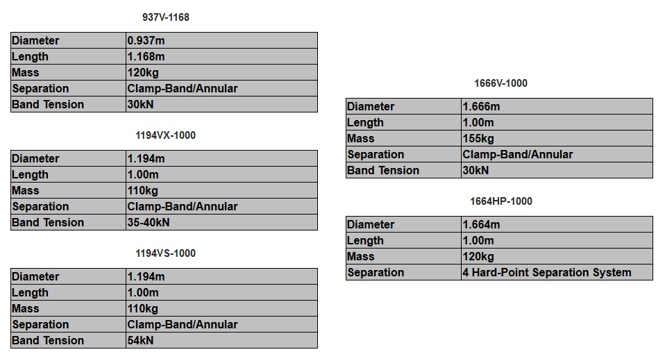
Payload Adapters interface with the vehicle and the payload and are the only attachment point of the payload on the Launcher. They provide equipment needed for spacecraft separation and connections for communication between the Upper Stage and the Payload. The separation system can be based on either the traditional pair of pyrotechnically-initiated bolt cutters or a low-shock Clamp Band Opening Device (CBOD). Four off-the-shelf Payload Adapters are currently available for Proton Flights, however custom designs based on Spacecraft requirements are also provided by Khrunichev, the manufacturer of Proton Adapters.