
Orion Spacecraft Overview
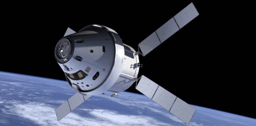
The Orion Multipurpose Crew Vehicle (MPCV) is a NASA spacecraft designed to take a crew of up to six Astronauts to destinations beyond Low Earth Orbit including the Moon, Mars and Asteroids.
Orion was born as part of the Constellation Program as the Crew Exploration Vehicle and lived on through the cancelation of that program, continuing under the MPCV designation as development proceeded toward initial test flights before operational crewed missions using the Space Launch System in the next decade.
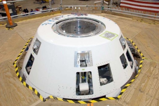
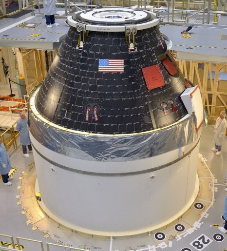
In its exterior design, the Orion Crew Module closely resembles the appearance of the Apollo Command Module, also using the 57.5-degree frustum shape.
Overall, the Crew Module (CM) will have a maximum diameter of 5.02 meters standing 3.3 meters tall with a launch mass around 8,900 Kilograms, offering an internal volume of 19.56 cubic meters , 8.95m³ of which will be habitable volume that can be accessed by the crew. Orion is designed to be able to support a crew for 21 days of active crew time plus 210 days in a quiescent mode which will require crews to be supported by Space Habitat Modules for long-duration flights to distant targets.
Although the spacecraft resembles the Apollo spacecraft, Orion will be using state of the art technology for all its systems to create one of the most advanced spaceflight systems ever developed. Orion also includes a capability of upgrades should more advanced systems become available in the future.
Orion Crew Module
Structure
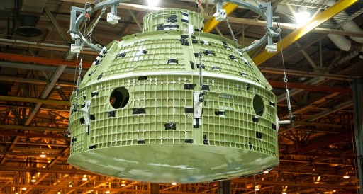
The pressure vessel and structural elements of the Orion spacecraft use olive-green aluminum-lithium alloy, the same was used for the Super Lightweight External Tank of the Space shuttle used for the majority of missions since 1998.
The crew module’s core structure, the pressure vessel, consists of a number of components – an aft bulkhead and aft bulkhead cap, the crew module barrel, the forward cone, the forward bulkhead and crew module tunnel that would interface with a docked spacecraft. These components are joined by self-reacting friction stir welding which produces superior bonds and allows for the joining of Al-Li alloys that can not be welded using traditional techniques.
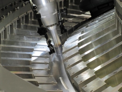
Friction stir welding (FSW) is an innovative process that delivers high quality and high strength welds in aluminum alloys. The process uses a rotating weld pin that plasticizes material through friction heating. The plasticized material is welded through the application of a high weld forge force through the weld pin tool. The high weld forge force is directed against an anvil and a stout tool structure.
In the self-reacting friction stir welding technique, two opposing shoulders are employed on the crown and root side of the weld joint with the forge force acting against the crown shoulder portion of the weld pin tool by the root shoulder. This eliminates the need for a stout tool which reduces the overall process cost.
The Orion crew module requires a total of 33 FSW welds that include some of the longest circumferential welds attempted to date using the FSW technique. Welding operations are completed at the Michoud Assembly Facility using the Universal Weld System II which includes a 6.7-meter diameter turntable, an FSW head and a modular T-grid floor.
The system offers five-axis welding on fixture-mounted hardware and achieves extremely precise welds. UWS II is operated by the University of New Orleans Foundation and NASA. It is the largest FWS rig in the world.
Forward Bulkhead, Aft Bulkhead & Barrel, Backbone Structure
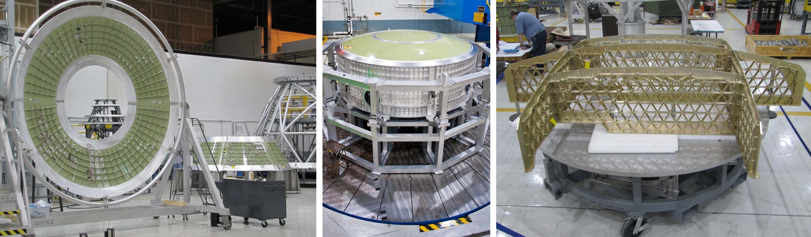
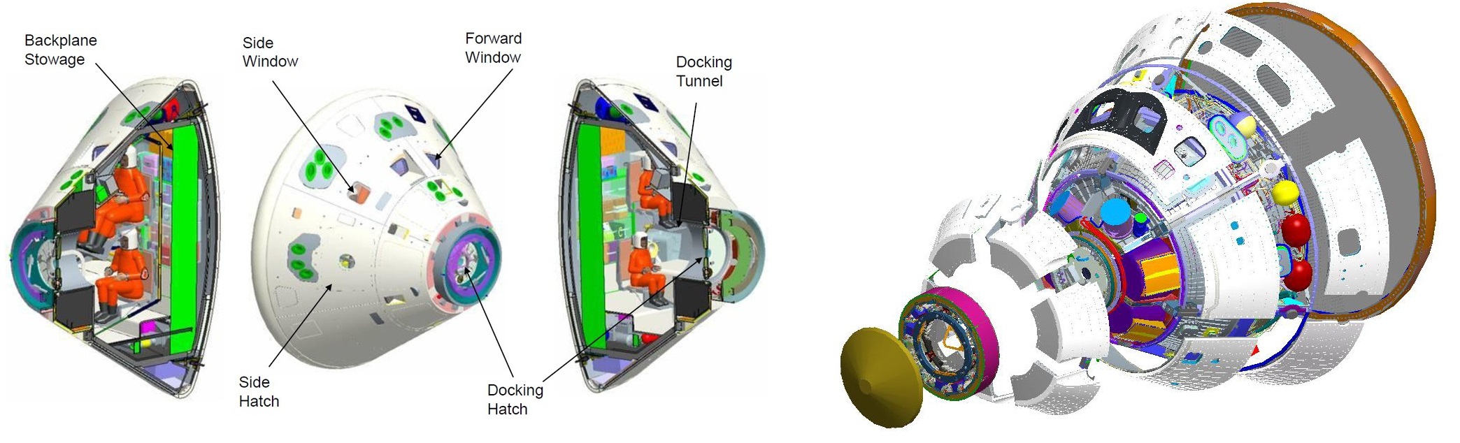
The Crew Module’s aft bulkhead and barrel sections serve as a mounting structure for the backbone assembly that uses an aluminum grid structure to provide additional rigidity to the module and offer attach points for crew seats, internal systems, and storage lockers. The cone installed atop the lower barrel section includes four windows – two docking windows looking forward and two horizon windows. This section also facilitates the vehicle’s side hatch for crew in- and egress.
The exterior of the pressure vessel offers mounting structures for a variety of equipment that is not required to reside within the pressurized volume of the spacecraft such as avionics systems, propellant tanks, environmental control system components, batteries and a variety of other components. The majority of external systems are located in the Forward Bay atop the forward bulkhead, installed around the crew tunnel leading up to the forward docking interface.
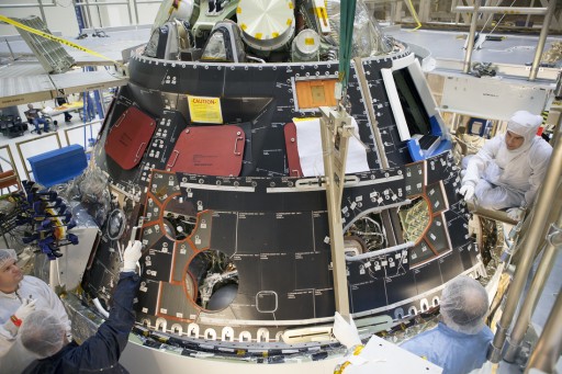
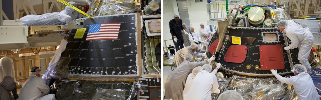
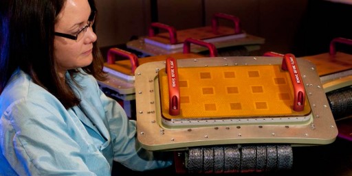
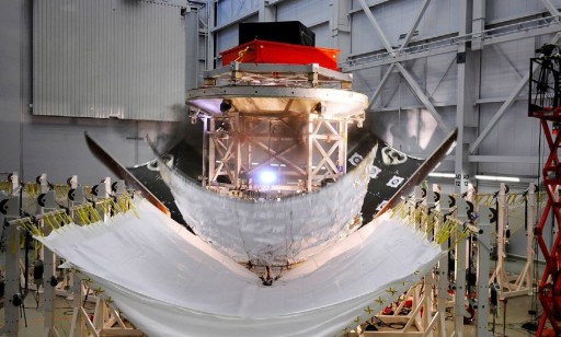
Installed around the pressure vessel and its various external systems are composite backshell panels with titanium honeycomb cores that provide primary thermal control to the spacecraft as well as micro-meteoroid orbital debris (MMOD) protection using laminate panels. A total of 49 composite panels make up Orion’s outer shell with additional thermal protection layers installed on top. A total of 970 TUFI coated AETB-8 thermal tiles with Space Shuttle heritage are installed on Orion’s backshell to protect the internal equipment from heating during re-entry. These tiles consist of silica glass fibers and have excellent thermal characteristics.
The forward bay is protected by a dedicated cover also using composite materials (see section on Orion’s parachutes). In the aft section, Orion’s core structure interfaces with the Heat Shield Support Structure consisting of a titanium skeleton that holds the heat shield.
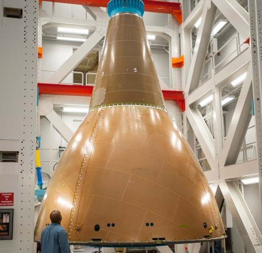
Backshell Installation
Heat Shield
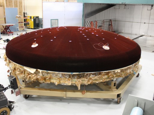
To withstand re-entry heating of up to 2,800 degrees Celsius when returning from Mars, the Orion spacecraft is equipped with the world’s most powerful heat shield which also is the largest ever built with a diameter of just over five meters.
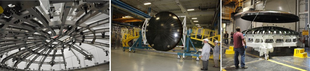
The heat shield uses a titanium skeleton that provides the interface points with the crew module and adds strength to the heat shield required for it to withstand the impact with the water at splashdown. The skeleton is held in place by six brackets on the CM aft bulkhead. Fitted atop the skeleton is a carbon fiber skin that provides additional strength and acts as mounting surface for the AVCOAT ablative heat shield material. This structure consists of one center, 18 gore and 18 shoulder panels.
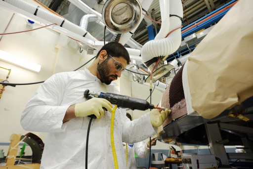
Originally developed by Avco, the AVCOAT technology is currently being provided by Textron and consists of an empty fiberglass-phenolic honeycomb structure that is attached to the carbon fiber structure and contains over 330,000 empty cells.
These cells within the honeycomb are then filled with the AVCOAT material using a hand gun. The AVCOAT layer is about 4 centimeters thick, 20% of that are expected to burn away during entry. The ablative material itself is an epoxy novolac resin with a number of additives to create a substance with a low density of 0.51g/cm³. During the re-entry process, pyrolysis of the material converts the material into a mixture of carbon and silica.
Titanium Skeleton, Heat Shield Skin & Skin-Skeleton Mate
The principle behind ablative heat shield technology is to create a boundary layer between the shield’s outer wall and the extremely hot shock layer gas by allowing the heat shield material to slowly burn away and, in the process, generate gaseous reaction products that flow out of the heat shield and keep the shock layer at a separation distance, reducing the overall heat flux experienced by the outer shell of the spacecraft.
The processes occurring at the heat shield material include a charring, melting and sublimation on the one hand and pyrolysis on the other. Pyrolysis creates the product gases that are blowing outward and create the desired blockage of convective and catalytic heat flux. Radiative heat flux is reduced by introducing carbon compounds into the boundary layer gas which make it optically opaque.
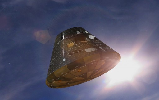
Orion’s heat shield is launched with a reflective cover installed over it to protect it from the cold temperatures encountered in space. This cover burns away in the initial stages of re-entry.
The current heat shield design may require modifications to the manufacturing process since the hand-filled AVCOAT material was more uneven than desired when Orion’s first heat shield rolled off the manufacturing line. Changes may also be necessary to fully certify the heat shield for re-entry energies occurring in Mars missions as the current version is only suitable for entry energies of lunar flights.
Propulsion System
The Orion crew module receives propulsive support from the Service Module for the majority of the mission. The SM includes the Orion Main Engine, an Auxiliary Propulsion System and a Reaction Control System that provide main propulsion capability and attitude control to the Crew Module from the moment of spacecraft separation from the launcher to the separation of the Orion Crew Module ahead of its return to Earth. (See Service Module Propulsion Section for technical details on its threefold propulsion system.)
The Crew Module itself hosts a high-flow hydrazine monopropellant Propulsion Reaction Control System comprised of 12 thrusters to control the vehicle’s three-axis attitude before and during re-entry. Hydrazine monopropellant is stored in two separate tanks that are pressurized from independent high-pressure helium tanks.
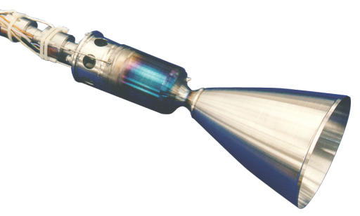
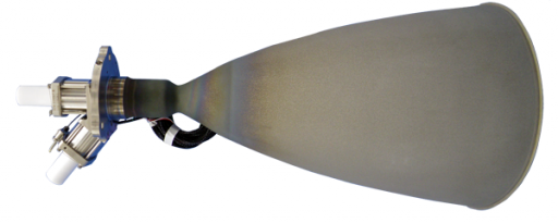
Orion uses 12 MR-104G catalytic thrusters manufactured by Aerojet Rocketdyne. The thrusters are part of the MR-104 family that provided in-space propulsion for a number of projects including Voyager and Landsat. The twelve engines are arranged in four single-engine pods and four dual engine pods to provide redundant control in yaw, pitch and roll.
The MR-104G thrusters each deliver 712 Newtons of thrust using catalytic decomposition of hydrazine over a heated metallic catalyst bed. The 104G version includes a number of improved design features that include a newly developed 120-Volt redundant propellant valve, a 120V/40W catalyst bed heater, new chamber pressure transducers and an integral thruster mount configuration. The pressure-fed thrusters are capable of operating in a wide range of conditions in terms of supplied propellant pressure.
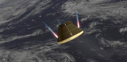
Orion uses its thrusters all the way through its Entry, Descent and Landing Sequence to maintain an appropriate attitude and modify lift to control its entry range and deliver the spacecraft to an on-target parachute deployment location. The thrusters are also active shortly before splashdown to assist Orion in achieving a good orientation for impact with the water. All thrusters are deactivated at the moment the touchdown is detected.
Electrical Power System

The Orion Crew Module receives power from the Service Module that includes the spacecraft’s power-generating solar arrays which deliver power to the CM via Power Control and Distribution Units in the Service Module and two Power & Data Units in the Crew Module Adapter. During free flight, eclipse and times of increased power demand, Orion relies on a total of six batteries to deliver power to the various systems of the spacecraft using four independent 120-Volt power buses. Switching from the heritage 28-Volt power systems to 120V DC allows wire gauges to be smaller due to the decreased current, reducing mass and creating a more capable power system.
Power delivered from the two Power & Data Units in the Crew Module Adapter is received by the Crew Module’s six Power & Data Units that control the state of charge of the Crew Module Batteries and distribute power to all Crew Module loads including the power system, battery controllers, network switch, monitoring and command systems, heater controllers, environmental control system driver, thermal control system driver, pyro driver, docking system, attitude determination and control equipment, communications subsystems and video systems.
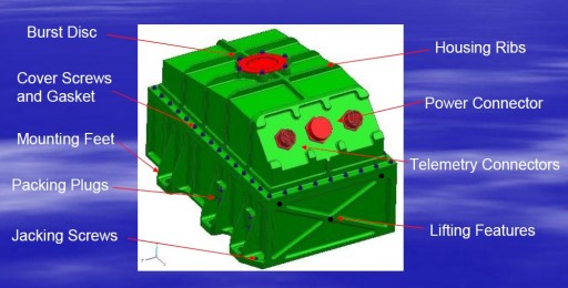
Orion’s Lithium-Ion batteries are manufactured by Yardney Technical Products, a company with decades of experience in space power storage systems. The development of Orion’s 120V batteries was filled with a number of challenges due to the restricted envelope and mass requirements that prompted the development of a new non-traditional forced shim assembly approach to pack the individual battery cells into the battery bay using a single leaf spring design to compress the cells into the housing.
Each battery weighs 44.8 Kilograms and consists of a four cell stack with eight NCP25-5 cells in each bay creating a capacity of 30 Amp-hours per battery. The battery assemblies contain internal fuse boards, control boards, heat sink equipment and monitor/equalization boards.
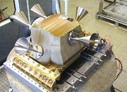
Avionics, Communications & Commanding
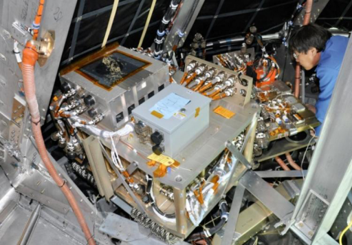
Orion’s Crew Module hosts a number of state of the art avionics units to handle data generated by onboard systems, control the various functions of the spacecraft, execute commands sent from Earth or by the crew and return systems telemetry for insight into systems status.
The brains of the Orion spacecraft is the Vehicle Management Computer manufactured by Honeywell. VMC is a robust system that is internally redundant and delivers more computing power to the Orion spacecraft than any previous crewed spacecraft had in the past. The VMC facilitates two high-integrity computing modules which are in charge of executing flight control and other software, a high density flash memory module, and an Ethernet network router module with hardline interfaces to all vehicle controllers that are operating the various onboard systems.
The computer is a single electronics unit consisting of four independent modules that deliver the processing capability for the Orion spacecraft and communicate with the other avionics of the Orion spacecraft via redundant Ethernet connections using TTEthernet Network Interface Controllers and network switches also developed by Honeywell.
The Ethernet Network System connects a variety of Crew Module systems including the communications terminal, the Video Processing Units, Absolute & Relative Navigation Systems, Power and Data Units, and Crew Displays and Controls.
The data system interfaces with the Service Module through the Crew Module Adapter’s Power Data Units. Overall, the onboard data bus moves data 1,000 times faster than systems employed on the Space Shuttle and the International Space Station.
The Orion crew module uses a high-speed communications system employing four phased array antennas that will be used for video, data and voice communications with the spacecraft as well as command uplink and telemetry downlink to ground stations or NASA’s Tracking and Data Relay Satellite Systems.
Attitude Determination
The Orion spacecraft is outfitted with a number of state of the art system to accurately determine its attitude in space in order to properly orient itself for the different phases of its mission.
Orion (starting with EM-1) carries star trackers manufactured by Ball Aerospace, each with a field of view of 8 by 8 degrees using a CCD detector to take images of the sky that are analyzed by internal software containing a catalog of thousands of star positions to allow the system to identify star constellations in order to precisely determine the spacecraft’s three-axis orientation. The star tracker operates at a high sample rate taking multiple images per second to keep track of star patterns to be able to track stars up to spacecraft rates of 4°/s.
Honeywell provides Orion’s Inertial Measurement Unit that includes a three-axis gyro system to accurately track spacecraft attitude and body rates throughout the mission from liftoff to splashdown. The OIMU uses radiation hardened components and is internally redundant to ensure proper functionality throughout all mission phases. IMU data is augmented by GPS data that is used to determine the spacecraft’s position in near-Earth space.
Rendezvous & Docking System
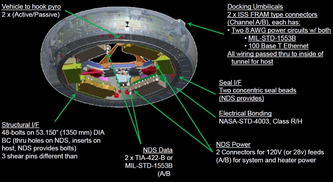
Located in the Crew Tunnel is Orion’s forward hatch and docking system which will be employed on missions that include planned dockings. Orion has been baselined for the NASA Docking System, NDS also known as the international Low Impact Docking System (iLIDS) that would allow Orion to dock to deep-space habitat modules, lunar/Mars landers or the Pressurized Mating Adapters of the International Space Station.
NDS is an androgynous design supporting low-impact technology. Automated and piloted Spacecraft docking and robotic spacecraft berthing will be possible with the NDS. The docking interface includes architecture to transfer data and power between the two vehicles with future systems also capable of propellant, pressurant and water transfers. The hatch diameter available to crews is 80 centimeters.
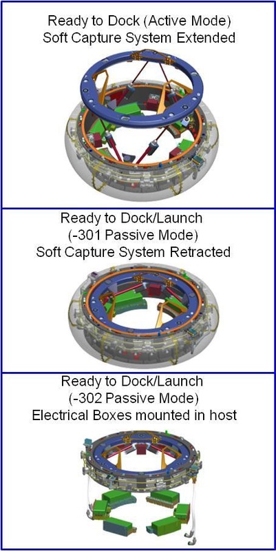
For a docking, one interface is in active mode with its Soft Capture System extended while the other spacecraft is in a passive role with its SCS in a stowed position.
The Docking System includes a Soft Capture System that forms the initial connection between the spacecraft before pulling the two docking systems together to allow the Hard Capture System to form a rigid seal between the two spacecraft. Hooks are available on the active and passive side of the docking system, providing up to 24 attachment points. Overall, the system consists of a capture ring, guide petals, soft docking magnets, mechanical latches, magnetic striker plates, latch strikers and sensor strikers. The strikers are part of the passive system and provide contact surfaces for components of the active system. Soft capture can be achieved using magnetic or mechanical soft capture latches.
The first elements to make contact are the guide petals that then correct any lateral or angular misalignment between the docking interfaces with soft capture being achieved either through magnets making contact with the striker plates on the opposing ring or through active latches that capture passive latch strikers to from a soft-mate. The SCS then aligns the two docking rings and through the retraction of SCS, the two Hard Capture Interfaces are positioned within their hard capture range to allow fine alignment by the HCS guide pins. Hooks are then used on either the active, passive or both sides to establish the structural connection between the spacecraft and achieving the required force to press the seals within the docking system against the other spacecraft. Each side includes 12 hooks – the passive and active hooks can both be closed if dictated by vehicle requirements.
When eventually linking up with other spacecraft, Orion employs a Vision Navigation Sensors and a high definition docking camera. VNS includes a flash LIDAR (Light Detection and Ranging) to image a target vehicle and calculate the precise range, bearing, alignment and orientation data. Coupled with the docking camera that delivers high resolution color video, the sensors deliver real-time three-dimensional images that can be used by software algorithms to be compared with the known shape of the target in order to guide the spacecraft to an on-target docking.
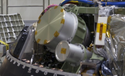
Parachute System & Recovery
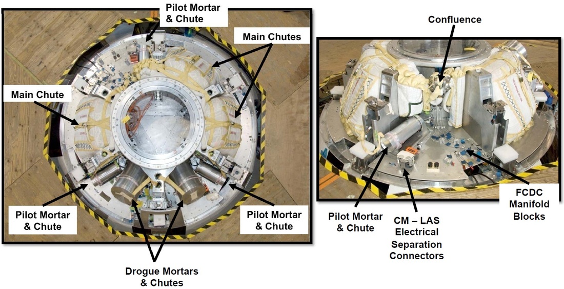
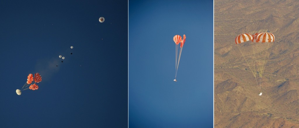
Returning to Earth from its missions, Orion performs a parachute assisted splashdown landing in the ocean using a combination of pilot, drogue and main chutes to slow down, transition to a vertical descent and make a relatively soft splashdown. The vehicle’s parachute system resides under the Forward Bay Cover, installed on the forward bulkhead and crew tunnel of the spacecraft.
The Forward Bay Cover is used to protect the equipment installed atop the forward bulkhead of the Orion Crew Module which offers a large volume for the installation of external hardware around the Crew Tunnel of the spacecraft. FBC is 2.6 meters in diameter and weighs 205 Kilograms. The cover consists to six composite face sheets with titanium honeycomb cores covered with TUFI-coated AETB-8 tiles (Toughed Uni-Piece Fibrous Insulation alumina-fiber-enhanced-thermal-barrier tiles). It protects the equipment installed underneath from the extreme temperatures during space flight and the heating environment during re-entry.
To expose the parachute system, the Forward Bay Cover has to be jettisoned by reliable mechanisms at an altitude of 7 Kilometers for the parachute opening sequence to begin.
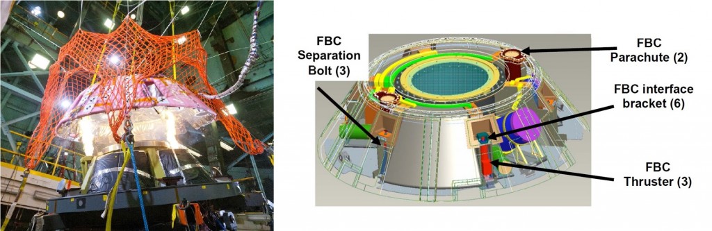
The Forward Bay Cover interfaces with the Forward Bay Gussets in three points using separation bolts that cut the structural connection when commanded by the spacecraft controller. Upon firing of the separation bolts, three thrusters are initiated to push the cover away from the spacecraft and ensure a clean separation without re-contact. Avoiding re-contact was an important consideration due to the unstable reverse flow in the wake of the descending capsule at separation velocities around Mach 0.5. The thrusters create a clean separation of the Forward Bay Cover that then deploys three parachutes.
Forward Bay Components & Cover Jettison Test
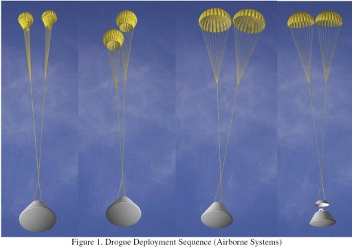
Orion’s parachute deployment sequence begins two seconds after the jettisoning of the Forward Bay Cover. Two pneumatic mortar systems use pyrotechnic gas generators to expel the two drogue chutes of the Orion Crew Module that are deployed 4.5 to 6.0 Kilometers in altitude when the spacecraft has reached a velocity of 480 Kilometers per hour.
Deployment of the drogue chutes is triggered based on altitude data delivered by a Primary GPS-aided Kalman filter. A backup system uses three barometric altimeters to trigger the parachute deployment at a sensed air pressure. Should both of these systems fail, Orion would rely on its Inertial Measurement Unit alone, delivering vehicle rates that are processed through a gravity model to calculate a rough estimate of the spacecraft’s altitude.
Subsequent events such as Main Chute deployment are based on time-tagged commands with the drogue deploy acting as reference time.
All of Orion’s parachutes consist of Kevlar and nylon, aiming to make them as rugged as possible while also minimizing the mass of the overall system. The chute design ensures that the parachutes operate in the extreme environment encountered during the initial deployment, also ensuring that normal wear and tear on the material will not impact the operations of the chutes.
The canopy of the chutes is made from nylon while all risers, lines and cords are Kevlar and steel – all parachute lines are bundles of up to six individual cables.
The drogue chute planform was designed from a conical circular shape for the canopy which itself is constructed by triangularly shaped gores, each consisting of a grid of horizontal and vertical ribbons. Gaps in between horizontal ribbons crate the geometric porosity of the chute. The chute consists of 24 gores and 55 ribbons, it has a cone angle of 25.7 degrees.
Each drogue is 7 meters in diameter and is suspended on a 10.5-meter line and 20-meter long riser. Flying under the drogue chutes for a little over a minute, Orion slows down to 160 Kilometers per hour, also dissipating horizontal velocity to reach conditions that are safe for the deployment of the main chutes.
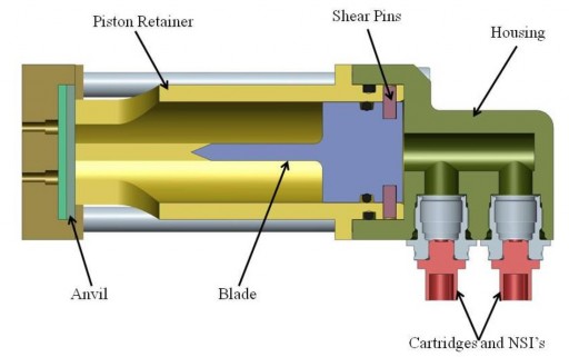
The drogue chutes are separated by a cutter assembly that uses a pyrotechnically initiated guillotine to severe the drogue parachute line. This cutter consists of a housing facilitating a steel blade, piston retainer, an anvil and shear pins. Two NASA Standard Initiator cartridges are used to generate a rapidly expanding gas that drives the blade forward as soon as the pins are sheared by the output pressure. After about 1.5 centimeters of travel, the blade hits the cable bundle and servers it before penetrating into the steel anvil behind the parachute line.
Once the landing signal has been provided through measurements of the Inertial Navigation System, the Main Chute lines will be cut using similar systems to avoid the chutes dragging the capsule into an upside down position.
The three main chutes are packed in bags installed in dedicated compartments in the Forward Bay of the Crew Module. Deployment of the mains is accomplished using three Pilot Chutes that are expelled from pneumatic mortars using pyrotechnic gas generators.
Unlike the drogue chutes, the Pilot Chutes employ a Ringslot design consisting of 12 gores and four ribbons creating an overall chute diameter of 3.0 meters. The Pilot Chute lines are 3.45 meters long while the risers measure 17.4 meters in length.
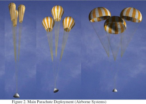
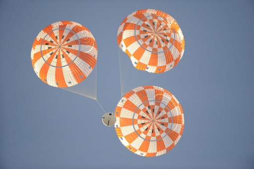
Once the Pilot Chutes are inflated, they generate sufficient force to pull the main chutes out of the parachute bags. Once entering the airflow, the three main chutes, each weighing 136 Kilograms, are inflated in stages, held to a certain opening level by a series of reefs. The initial reefing condition allows the chutes to open to about 3.5% to continue slowing down the capsule. Once the first set of reefs are cut, the chutes open to 11% of their capacity, held by another set of reefs. After stable flight under the second reefing stage, the final reefs are cut and the chutes open up to their full diameter of 35.4 meters.
Descending under the white-and-red main chutes, Orion slows down to a landing speed of under 30 Kilometers per hour for a splashdown in the ocean. Orion can tolerate the failure of one of the three main chutes and still return at a benign landing speed.
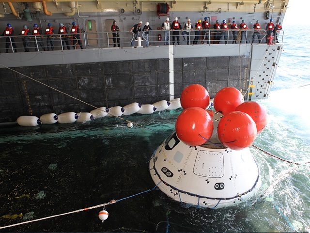
After landing, a series of five balloons that are attached to the Forward Bay of the Crew Module are inflated as part of the vehicle’s Crew Module Uprighting System that would allow the craft to return to an upright posture after coming to rest on its side or even upside down.
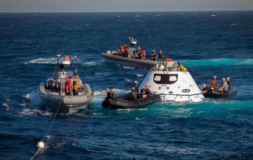
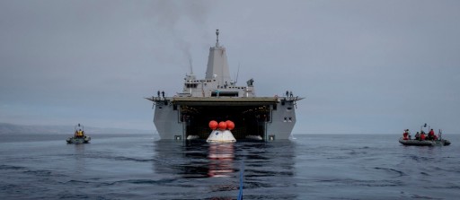
Orion’s recovery at sea is an effort involving several vessels and helicopters. At the forefront will be a Navy Landing Platform/Dock (LPD) ship, equipped with a floodable hangar normally used to launch and retrieve watercraft. The USS Anchorage will be the primary recovery ship in an effort coordinated between the US Navy, Lockheed Martin engineers and NASA’s Ground Systems Development and Operations (GSDO) program.
For landing, helicopters will be in the air to observe and locate the spacecraft and components that are released during the landing sequence. Navy divers approach the Orion spacecraft in Zodiac boats and inspect the vehicle and its surroundings for any hazards before beginning to attach a sea anchor, and load-distributing collar and tether lines to guide the spacecraft to the well deck of the USS Anchorage. Once inside the flooded deck, the capsule is winched in place and positioned atop a set of rubber shock absorbers to allow water to be drained from the deck. Once secured, Orion can be placed in its recovery cradle for return to shore and post-flight processing.
Another Navy ship, the USNS Salvor will be present to recover the main chutes, the Forward Bay Cover and the drogue chutes using a crane to lift the hardware on deck. For crewed Orion missions, the returning crew members would remain inside the spacecraft until the capsule is secured in the dry well deck of the recovery ship. Crews would exit the spacecraft via a platform moved into position next to the secured spacecraft.
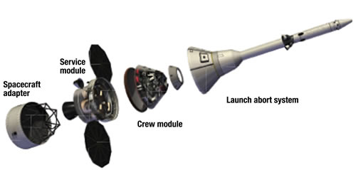
Launch Abort System
Orion’s Launch Abort System uses a Launch Escape Tower during the initial stages of flight to carry the spacecraft away from the launch vehicle in case of a failure during ascent. In later ascent stages, the Orion spacecraft would use its own propulsion system to separate from the rocket and either enter a lower-than-planned orbit or return to Earth for a contingency landing.
Like the Russian Soyuz spacecraft, Orion will have launch abort capability from before liftoff all the way to orbital insertion. The Launch Escape Tower approach has been employed since the early stages of the space program and continues to be used in major programs such as Soyuz and Shenzhou with a vast heritage on the U.S. side beginning with the Mercury Program and continuing with Apollo.
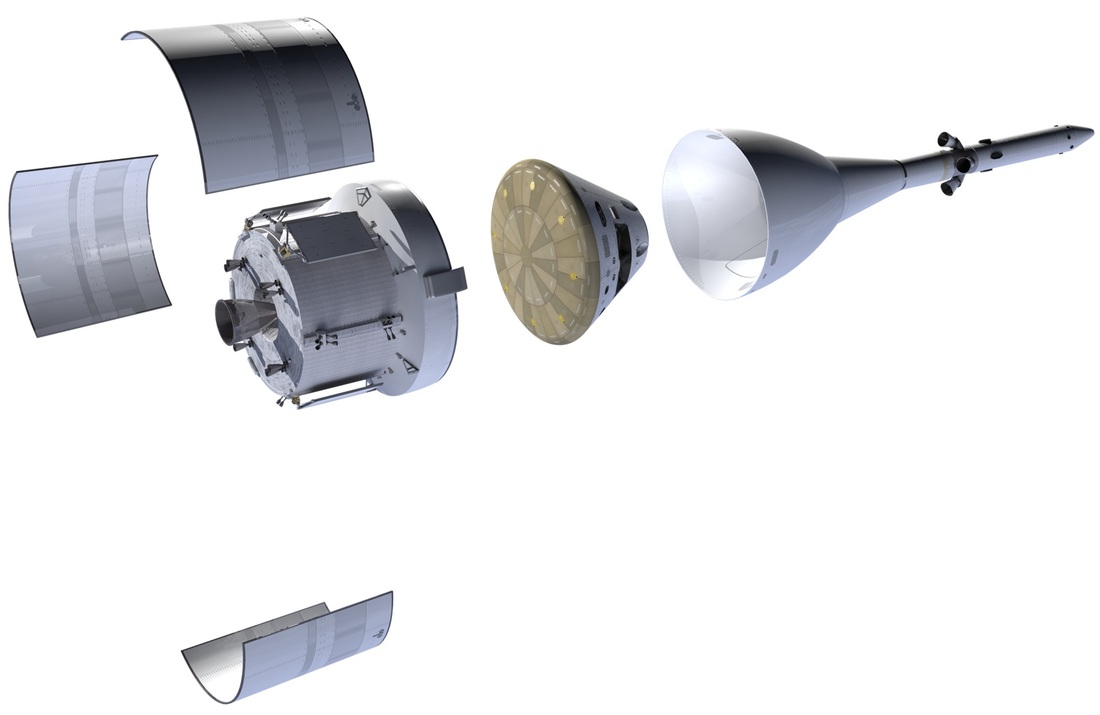
Orion’s Launch Abort System (LAS) consists of six components – from top to bottom: a nose segment, the Attitude Control Motor, Forward Interstage, Jettison Motor, Abort Motor and Fairing Assembly. Overall, the Escape Tower stands about 13.3 meters tall with a loaded mass of over six metric tons.
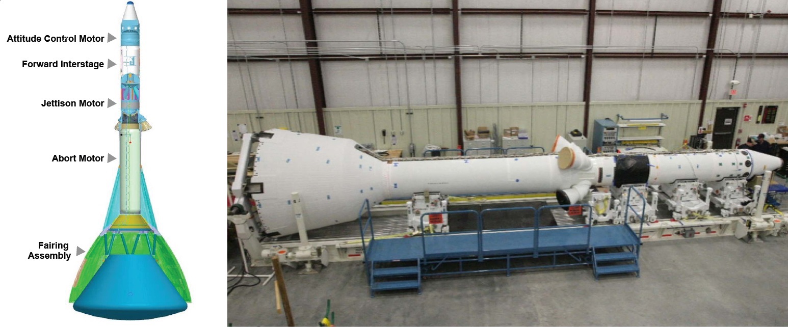
The Fairing Assembly encloses the Orion spacecraft during its stay on the launch pad, during atmospheric flight and during operation of the Launch Abort System to protect the spacecraft from thermal and dynamic loads seen in the abort sequence. The fairing assembly weighs approximately 1,350 Kilograms and consists of two components – an ogive fairing that encloses the Orion Crew Module and an upper Fillet that interfaces with the escape tower itself.
The Launch Abort System interfaces with the Crew Module via six attach points in the forward bay of the vehicle using the Motor Adaptor Truss Assembly (MATA) containing the structural attachment and separation system of the LAS.
Called Retention and Release System, the system has to be able to maintain a structural connection between the Crew Module and the LAS until the Jettison Motor fires to move the LAS away at which point the structural connection has to be cut. The six Retention and Release Mechanisms are installed above the six primary longerons of the crew module’s forward bay. Each mechanism consists of frangible nuts that are holding pre-tensioned studs from the LAS side, initiated with two booster cartridges. Different frangible nut detonators were tested using the Orion Ground Test Article to select the system that showed the lowest separation shock.
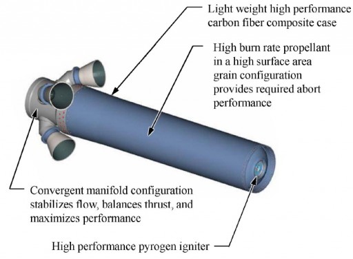
The lower segment of the Launch Abort System facilitates the Abort Motor that is manufactured by ATK (Alliant Techsystems). The AM consists of a carbon-fiber composite case that holds the solid propellant consumed by the motor. On top of the case is the convergent manifold that contains four nozzles employing a turn-flow design which means that the exhaust flow of expanding gas is directed through a turn to generate thrust in the desired direction. The four nozzles (spaced 90 degrees) are canted 25 degrees from the motor central line creating a total turn of 155 degrees.
The titanium manifold is designed to stabilize the exhaust flow, balance the thrust across the four nozzles and maximize overall engine performance. AM uses a solid propellant with a high burn rate achieved by using a mixture containing high surface area grains allowing the motor to achieve the required abort performance. The motor is ignited by a high-performance pyrogen igniter that is capable of starting the solid rocket motor with extremely low latency to achieve spacecraft motion within a few milliseconds after the abort command is issued.
The 3,464-Kilogram Abort Motor delivers 1,760 Kilonewtons of thrust along the vehicle axis to pull the spacecraft away from the failing launch vehicle. The motor achieves a seal level impulse of 245s. AM consumes most of its propellant during the first three seconds of operation with thrust residuals beginning to tail off after about seven seconds. In abort scenarios, crews endure over ten Gs when being pulled away from the launch vehicle.
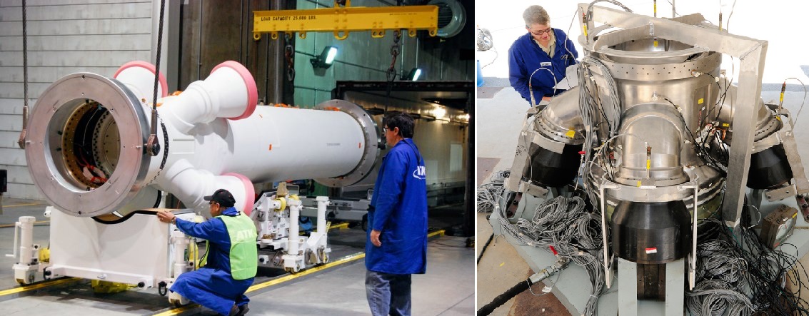
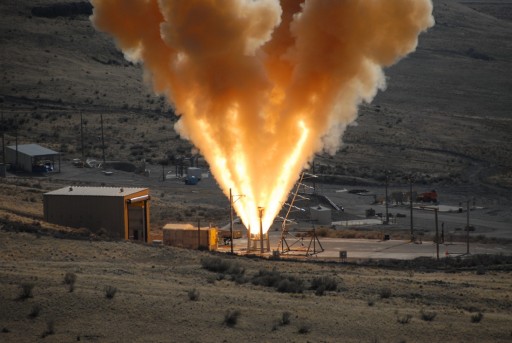
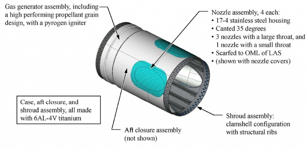
Residing above the Abort Motor is the Jettison Motor, weighing 410 Kilograms. It is responsible for pulling the separated Launch Abort System away from the Crew Module in both, nominal flight and abort scenarios. The JM was developed by Aerojet Rocketdyne and consists of a Shroud Assembly, a Nozzle Assembly and a Gas Generator Assembly.
The clamshell Shroud Assembly includes structural ribs for reinforcement and provides the interface to the Abort Motor in the aft and the Interstage Adapter in the forward direction. All structural components consist of 6Al-4V titanium alloy. The Interstage is provided by Orbital Sciences.
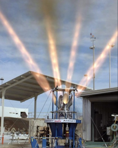
The Nozzle Assembly contains four nozzles all made from 17-4 stainless steel, canted 35 degrees from the centerline of the Launch Escape Tower. Three of the nozzles have a large throat while one has a smaller throat to create a thrust offset that places the LAS on a trajectory leaving the flight path of the launch vehicle.
The Gas Generator is located above the nozzle assembly since the JM does not employ turn-flow technology. High-performance propellants are initiated by a pyrogen igniter to create high pressure gas feeding the nozzles.
The JM delivers a total thrust of 178 Kilonewtons (147kN axial) at an impulse of 221 seconds over the course of 1.7 seconds of burn time.
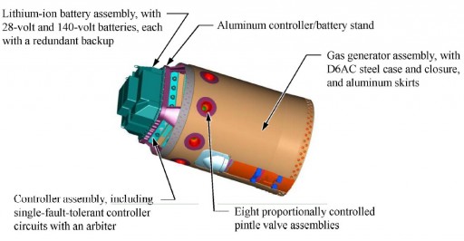
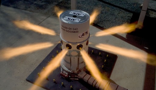
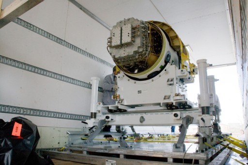
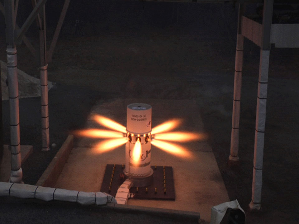
Stacked atop the JM and Interstage is the 760-Kilogram Attitude Control Motor (ACM) that is used to stabilize the stack during the launch abort and provides the re-orientation maneuver to put the crew module into the correct attitude for separation and parachute deployment. ACM is a product of ATK.
The ACM consists of a D6AC steel case and closure with aluminum skirts to provide stability to the gas generator that burns solid propellant to deliver high-pressure gas to the nozzles. A total of eight nozzles are installed on the motor with a radial spacing of 45 degrees to be able to provide directional thrust components to control pitch and yaw during the abort sequence. Thrust on each nozzle is regulated individually by pintle valves in each of the thrusters as commanded by the ACM controller.
During the first seven seconds of operation (coinciding with the firing of the Abort Motor) the ACM can deliver up to 58 Kilonewtons of thrust that can be distributed and balanced between one and all ACM nozzles. From +7 to +27 seconds, the ACM will operate at a thrust level around 22.3 Kilonewtons.
The ACM assembly includes a battery stack comprised of 28-volt and 140V batteries, each with a redundant backup to feed the ACM controller and actuate the pintle valves to the commanded thrust settings. The ACM controller uses a single-fault tolerant architecture and receives inputs from the Guidance Platform of the Command Module to compute the required thrust setting to achieve the planned attitude.
The ACM working principle includes two phases of operation – the boost phase during which the Abort Motor is fired and followed by a directional control phase during separation from the launch vehicle. After burnout of the AM, the ACM is commanded to initiate a pitch maneuver to deliver Orion to a heat-shield forward attitude in preparation for LAS jettison and parachute deployment.
A number of abort modes have been developed for Orion provide abort capability from from pre-launch to orbital insertion.
In a Pad Abort and Low-Altitude (<7.5km) scenario, Orion would fire its Launch Abort System in case of its launch vehicle suffering a major failure prior to launch or during ignition when crew emergency egress is no option. The LAS Abort Motor and ACM would ignite simultaneously and a Separation Ring would actuate the separation of the Command Module from the Orion Service Module to allow only the crew module to be pulled away by the LAS. After seven seconds, AM thrust tails off and three seconds later, ACM initiates the pitch-over that takes about six seconds to complete during which the vehicle reaches its apogee altitude of nearly 2 Kilometers.
The Jettison Motor fires after 21 seconds to separate the Crew Module. The Forward Bay Cover is jettisoned after 22 seconds followed by the deployment of the Drogue Chutes just over thirty seconds after the abort is initiated. The Pilot Mortar fires a little over 50 seconds after the abort to slow the vehicle down to its touchdown speed for a splashdown in the Atlantic Ocean just off the coast of Florida in an established landing zone.
In the event of a mid-altitude abort from 7.5 to 45.5 Kilometers in altitude, the LAS is commanded to fire and the ACM and AM are ignited with the Separation Ring releasing the Crew Module to be pulled free of the failing launch vehicle. After operation of the Abort Motor, Orion is taken through its pitch-over by the ACM and enters a short free falling segment, still retaining the LAS. The Launch Abort System is released at the appropriate altitude for parachute deployment.
A high-altitude abort up to 100km in altitude is also accomplished by firing the LAS to pull the vehicle away from the launcher and includes the pitch-over to point Orion to a good direction for re-entry into the atmosphere. After ACM burnout, the JM fires and LAS is separated while Orion continues on its own using its Hydrazine attitude control system to maintain a nominal orientation throughout entry, taking the craft to the drogue deployment altitude.
After LAS and fairing jettison, Orion will still have launch abort capability. In case of a serious issue with the launch vehicle, all engines would be shut down by emergency command and the Orion-Service Module stack would separate by firing its own Main Propulsion System. This will either leave the spacecraft on a path towards re-entry or in a lower than planned orbit depending on the timing of the abort.
Orion will also have an Abort Once Around (AOA) feature in which it will perform a retrofire during its first orbit for a landing in the Pacific in the event of major systems problems aboard the spacecraft or an off-nominal orbital insertion. With SLS, there will be a limited Abort To Orbit (ATO) capability which involves a restart of the second stage to correct an erroneous orbit or deliver the stack from a sub-orbital to an orbital trajectory.
Crew Module Adapter
The Crew Module Adapter (CMA) is an interface ring that builds the structural connection between the Crew Module and the Service Module. It houses communications, electronics and power equipment and includes an umbilical device that connects electrical, data, and fluid systems of the SM to the CM.
The CMA includes two Power & Data Units that deliver power & data from the Service Module to the Crew Module and also control the state of charge of two batteries within the CMA. The adapter includes its own thermal control system components, receiving cooling from the Service Module via fluid interfaces. CMA also includes an S-Band communications system interfacing with the Crew Module.
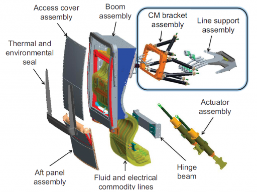
The primary interface between the Service and Crew Modules is an umbilical that consists of a boom which routes the various commodity lines to an umbilical plate on the Crew Module. The Crew Module Umbilical consists of a rigid boom assembly, a Crew Module bracket and line support assembly interfacing with the CM, an access and thermal cover, a harness of fluid and electrical commodity lines and a hinge with actuator assembly. The assembly is about 1.5 meters long.
The Umbilical Assembly includes four thermal control loop fluid interfaces, two Water Delivery System interfaces, four Gas Delivery Lines and a number of electrical and data interfaces that connect the power system of the Crew Module to the Power Control and Distribution Units in the SM and CMA and to establish a data connectivity to the Service Module and Launch Vehicle. All interfaces are located within two plates, male interfaces are on the Service Module Side while the Crew Module’s plate facilitates the female side of the interfaces.
Fluid connectors are quick-disconnects that use a proprietary Lockheed Martin Design including a dual O-Ring seal to maintain tight tolerances for leakage requirements.
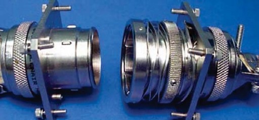
The electrical connectors use a zero separation force design that employs springs on the plug side to disengage the pins from the sockets without needing any external force. Electrical connectors in the interface use anti-binding features.
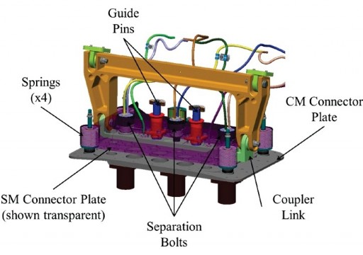
The two Umbilical Plates are firmly joined by three separation bolts that hold the two sides of the interface in tight contact throughout the mission. Once the separation command from the Crew Module is received, a two-stage separation process is set into motion that begins with the firing of the center separation bolt that disconnects the SM plate which then slides up along two guide pins, pushed up by four loaded springs in the corners of the plate. This motion of the SM plate disconnects all umbilicals creating an initial separation distance between all plugs and sockets while the two plate structures are still held together by two separation bolts.
Once the plate has reached a hard stop, the two remaining bolts are fired to structurally disconnect the two plates. The Umbilical Boom is then pushed away by the actuator on the SM side to move outward and out of the way of the Crew Module’s departure path.
This two-stage separation process avoids issues with misalignment of the connectors that occurs when the separation is completed in one single step. Only the Crew Module bracket and line support assembly stay with the Crew Module while the boom assembly and all associated systems remain attached to the Service Module after separation.
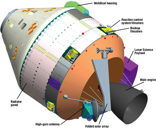
Service Module
The Purpose of the Orion Service Module is to support the Crew Module and the crew members over the course of the space flight by supplying electrical power generated by solar arrays, providing propulsion capability, facilitating the consumables such as water and pressurized gases and holding various systems such as environmental control and thermal control equipment.
The first flight of Orion, EFT-1 in 2014, does not use an operational Service Module since it is not needed for the two-orbit mission. EM-1, Exploration Mission 1 planned for 2018, will fly a Service Module provided by the European Space Agency based on the Service Module of the Automated Transfer Vehicle. No firm contracts have been made for missions past EM-1, however, ESA will deliver spare parts for the EM-1 SM that could be used to assemble another unit for use on EM-2 which will be Orion’s first crewed mission. NASA officials have expressed interest in continuing the ESA involvement, but no firm contracts were awarded beyond the first flight model which is provided to NASA’s for ESA’s use of the International Space Station from 2017 through 2020 when ATV is no longer flying.
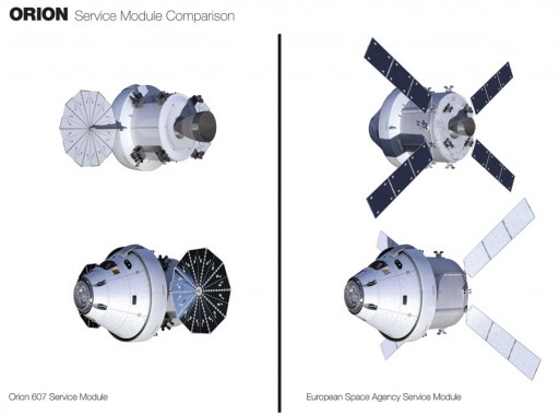
Original Service Module
Initially, Orion was planned to use a U.S. built Service Module based on Apollo and Space Shuttle technology, but switching from power generation through fuel cells to solar arrays. Plans called for a cylindrical Service Module measuring 5.03 meters in diameter and 4.78 meters in length using Aluminum-Lithium alloy structural components. The module was baselined for a dry mass of 3,700 Kilograms.
The module would have facilitated radiators to reject excess heat from the electronics in the Service and Crew Modules by circulating a mixture of water and glycol through cooling loops in the two modules of the spacecraft. Electrical power was to be generated by two Ultra-Flex solar arrays provided by ATK with dedicated avionics conditioning redundant power buses at 120 Volts.
The propulsion system featured a unified architecture with the craft’s main engine and Reaction Control System thrusters fed from the same hypergolic propellant tanks. The main propulsion system would use a single Orion Main Engine, a refurbished and modernized Space Shuttle Orbital Maneuvering System Engine delivering 27 Kilonewtons of thrust. Several Reaction Control System thruster pods would be used for attitude control and fine-maneuvering and to serve as a backup to the main engine. The Service Module was planned to have a fuel capacity of 8,300 Kilograms.
The Environmental Control System was designed to feature a pair of LOX tanks and smaller Nitrogen tanks to provide the crew with breathable air and pressurization between 10.2 and 15.05 psi. Lithium Hydroxide cartridges were planned to be used to scrub carbon dioxide from the cabin atmosphere and circulate scrubbed air into the spacecraft. Due to the switch from fuel cells to solar arrays, the Service Module was planned to be outfitted with a water tank to deliver drinking water to the crew. Adapting systems in use aboard ISS, Orion was planned to convert waste water and urine into drinking and cooling water.
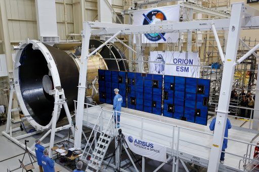
ESM – European Service Module
The ESA Service Module is currently (late 2014) in the midst of its design and review process and design specifications are subject to change. The overall design calls for the Service Module to employ technology developed for the Automated Transfer Vehicle. While ESA is responsible for most of the design and components, NASA, Lockheed Martin and their subcontractors are providing the Main Propulsion System, a number of network cards and design specs for umbilical and structural interfaces of the SM with the Orion crew module.
ESA’s Service Module design, known as ESM, uses Aluminum-Lithium alloy for its structural components including an aluminum framework that acts as a thrust structure to transfer loads from the Main Propulsion System through the entire spacecraft stack. Overall, the ESM will be 4.5 meters in diameter and 2.72 meters long, main engine excluded. The ESM has a projected dry mass of around 3,800 Kilograms and is capable of carrying up to 9,200 Kilograms of propellant.
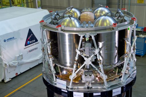
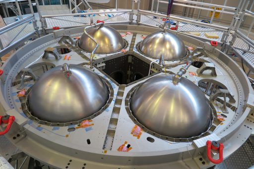
Structurally, the ESM consists of a number of basic building blocks – an upper cylinder, a tank platform, a main cylinder, a lower platform, an equipment deck and Micrometeoroid Debris Protection Systems. ESM consists of six longerons that interface with the Crew Module Adapter and directly support external equipment such as propulsion pods and the Solar Array Wings. A Tank Bulkhead supports the four propellant tanks and other consumable tanks. Internally, a system of radial shear webs and a square web assembly provides mounting structures for the various ESM systems. The webs interface with the longerons and bulkhead.
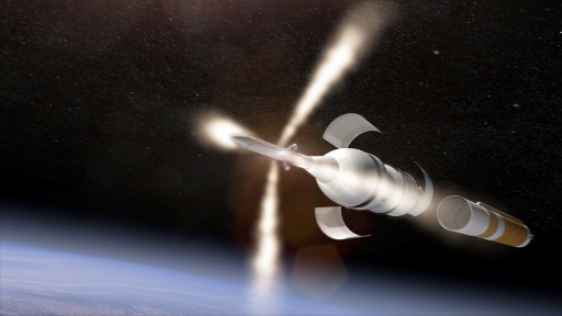
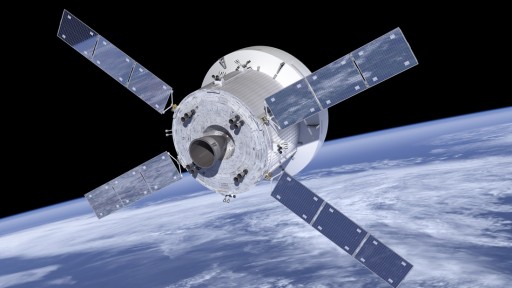
ESM continues the use of ATV’s characteristic “X-Wing” solar array arrangement with four deployable arrays that create a total spacecraft span of 18.8 meters. Compared to ATV, Orion’s solar arrays will be slightly shorter but wider than ATV’s and the solar cells used on the arrays will be more efficient through the use of triple-junction Gallium-Arsenide cells that have an efficiency of close to 30% compared to the 17% efficiency of ATV’s panels. ESM generates a nominal power of 11,100 Watts.
Each of the solar arrays consists of three rigid panels that consist of Carbon Fiber Reinforced Polymer covered triple junction GaAs solar cells that are connected in nine strings.
The wing is connected to the spacecraft structure via a two-degree of freedom Solar Array Drive Assembly that allows the array to be oriented in two independent axes by the Solar Array Drive Mechanism that is actuated by the Solar Array Drive Electronics (two units, each with two channels) which use inputs from sun and attitude sensors to optimize solar array pointing for maximum power generation. Power from the Solar Array Wings is routed through the drive assembly to the Power Control and Distribution Units. There are two PCDUs, each with two-channels to independently process electrical power from the arrays.
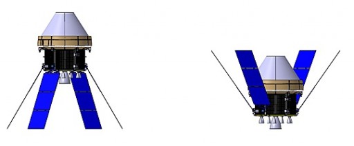
Orion’s solar arrays include a canting function in addition to the rotation of the arrays. This feature is exercised during the operation of the main engine to reduce loads on the arrays. During posigrade maneuvers (acceleration, positive delta-v), the arrays enter a –60-degree position to the inner axis which would be the case for Trans-Lunar Injection. For retrograde burns (deceleration, negative delta-v), the arrays are canted +55 degrees to the opposite direction (e.g. Lunar Orbit Insertion).
The Power Control and Distribution Units generate the four fully independent 120-Volt main power buses of the spacecraft and distribute power to all ESM users and to the Crew Module via the Crew Module Adapter. The PCDUs also provide bus protection. From the PCDU, power is routed directly to the Service Module System and to two Power & Data Units in the Crew Module Adapter that route power to the Crew Module, to possible unpressurized payloads and to two batteries within the Crew Module Adapter.
Control of all Service Module Systems on a high level is performed by the Orion Vehicle Management Computer that controls the central SM FT Processor of the ESM that is in charge of commanding the various downstream controllers which include the 4-channel Solar Array Drive Electronics, two 2-channel Power Control and Distribution Units, one 2-channel Command and Monitoring Unit, two Propulsion Drive Electronics units and two 2-channel Thermal Control Units. ESM uses a 1000 Base-CX ODN Ethernet bus for the exchange of telemetry and commands between the individual controllers while analog links are used for the operations of two sun sensors and sensors within the SLS interfaces. RS-422 serial links are supported for unpressurized payloads through comm equipment within the CMA. Within individual systems chains, digital and analog data buses are employed.
The ESM Thermal control system collects and rejects thermal loads generated in the Crew Module and ESM equipment and is capable of rejecting a thermal power of 5 Kilowatts. The system is comprised of two fully independent thermal control loops operating in hot redundancy mode. Each loop circulates cooling fluid through six external radiator panels with radiator loop temperature being controlled by 3-way mixing valves.
The system receives a cold and a warm fluid output from the Crew Module that is combined with the outflow from the Crew Module Adapter and the ESM avionics bay. Both loops include a Pump Package Assembly that consists of a pump and accumulator to force the fluid through the loops. The amount of fluid passing through the radiator and the portion of flow directed back into the circulation depends on readings from triple-redundant temperature sensors that provide feedback to the 3-way mixing valves that control the flow through the radiators and back into the system.
On-off valves are used to select one of two redundant loops if required. The inflow from the Thermal Control System is then directed back to the Crew Module Adapter and the CM umbilical as well as the SM Avionics Bay.
Within the avionics bay, cooling fluid is circulated through four coldplate assemblies to transport heat away from the major electronics components – the Control and Management Unit, the two Thermal Control Units and the two Power Control and Distribution Units.
The Passive Thermal Control System of the ESM consists of heaters and multilayer insulation. All Thermal Control System components are controlled via the Thermal Control Units that are also in charge of controlling the Consumables Storage System (CSS).
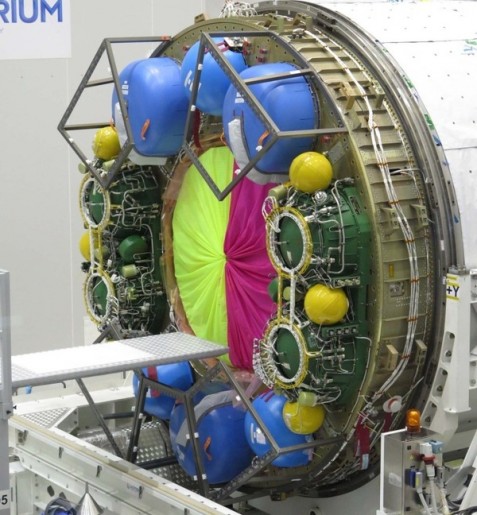
The CSS is comprised of two major segments, the Water Delivery System and the Gas Delivery System. The Water Delivery System consists of six metallic bellow tanks with a total capacity of 280 Kilograms. Each tank interfaces with a double distribution line that feeds water to the Crew Module Adapter where it is either used on a Sublimator Assembly or routed to the Crew Module Umbilical to be transported into the crew cabin for consumption.
Each of the six water tanks includes temperature and pressure sensors as well as heaters that keep the water from freezing. The various water lines also include heaters and a number of on-off valves that can isolate individual tanks and lines in the event of leaks. The water system is loaded via a Ground Support Equipment interface in the Crew Module Adapter. Pressurization is provided by the Nitrogen Gas Delivery System that delivers pressurant via a series of lines, valves and regulators.
The Gas Delivery System consists of separate tanks and plumbing for the Oxygen and Nitrogen System. A total of four gas tanks are installed in the ESM, each with a capacity of 33 Kilograms of gas stored at 275 bar. The Oxygen Delivery System is comprised of two tanks that interface with a redundant system of two delivery lines that can be selected and isolated via a series of valves.
The tanks and lines include pressure and temperature sensors, heaters and regulators that control the pressure at which Oxygen is delivered to the Crew Module Umbilical. The Nitrogen Delivery System is fed from one tank that interfaces with two delivery lines that include temperature and pressure sensors, on-off valves and pressure regulators. A fourth tank can be connected either to the N2 or O2 system via a jumper based on mission requirements. The Gas Delivery System is loaded through GSE interfaces in the Crew Module Adapter.
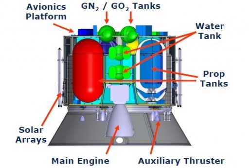
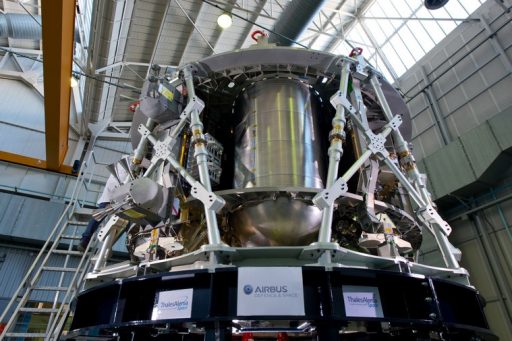
The Propulsion System of the ESM includes three different types of thrusters – a single Orion Main Engine based on the Shuttle’s OMS engine, eight Auxiliary Thrusters from ATV and Apollo and 24 Reaction Control System thrusters in eight pods, also from ATV and Apollo. The Propulsion System is controlled by the Propulsion Drive Electronics that operate with built-in redundancy and have been demonstrated on the ATV spacecraft. The PDE handles commands from the flight computer and delivers status telemetry of all propulsion system components.
The ESM propulsion system employs a unified architecture – all thrusters are fed from the same tanks. ESM uses Monomethylhydrazine as fuel and Mixed Oxides of Nitrogen as oxidizer (MON-3 – Nitrogen Tetroxide with 3% Nitric Oxide). Each propellant component is stored in two tanks that operate in series and the fuel and oxidizer systems use independent pressurization system.
High-pressure Helium is stored at 340 bar in a spherical tank and fed to the propellant tanks via a Pressure Control Assembly that employs internal redundancy to keep the tanks at a pressure of 20 to 25 bar. The propellant tanks are kept at temperatures below –5°C for MON-3 and under 50°C for MMH.
All ESM engines are pressure-fed. Propellants are supplied to the main engine by two main propellant lines that also feed the Auxiliary thrusters and RCS engines which are separated in two banks.
The Orion Main Engine a refurbished/modernized Orbital Maneuvering System engine used on the Space Shuttle which in turn is an Aerojet Rocketdyne AJ10-190 engine that itself is part of a family of engines used on the Apollo Service Module and a number of launch vehicles.
The pressure-fed AJ10-190 engine consists of a stainless steel combustion chamber, throat and upper nozzle segment, all with nickel closure.
The nozzle is radiatively cooled, consisting of a niobium shell. Overall, the engine measures 1.91 meters in length and has a nozzle diameter of 1.09 meters while the chamber is 26.4 centimeters in diameter. The tapered conical fuel manifold of the engine is located on the upper nozzle segment to allow the fuel to cool the upper nozzle and combustion chamber, flowing through 120 groove coolant passages before entering the combustion chamber and self-igniting when coming into contact with the oxidizer injected through the oxidizer inlet.
The engine operates at an oxidizer to fuel ratio of 1.65, has an area ratio of 55 and operates at a chamber pressure of around 8.6 bar. In its OME version, the engine generates 27.7 Kilonewtons of thrust at a specific impulse of 316 seconds. It consumes 5.4kg of MON-3 and 3.3kg of MMH per second, being capable of long firings over 1,200 seconds in duration. The Orion Main Engine will employ a thrust vector control system to provide pitch and yaw control during its burns.
Eight Auxiliary Thrusters, each delivering 490 Newtons of thrust, will be installed on the aft section of the ESM to provide fine maneuverability and act as a backup to the Orion Main Engine. The engines are R-4D-11 thrusters manufactured by Aerojet Rocketdyne and originally designed by the Marquardt Corporation for use on the Apollo Service and Lunar Modules.
The engine in its different versions is also used on a number of satellites as an apogee motor. The engine has a dry weight of 3.63kg and is 55.4cm in length and has a nozzle diameter of 27.9cm. The engine is fixed and does not provide gimbaling capability. It is a pressure-fed thruster with a fuel flow rate of 0.05kg/sec and oxidizer flow rate of 0.09kg/s creating a chamber pressure of 7.45bar.
The engine’s nozzle consists of welded coated columbium (niobium) that is radiatively cooled and film-coated. R-4D can perform continuous burns of up to 1 hour, generating a specific impulse of 312 seconds. Short firings with a minimum impulse bit of 2.67 Ns are also possible.
Twenty four 220N Reaction Control Thrusters are installed on the ESM in four pods of two engines and four pods containing four thrusters to create an arrangement that delivers redundant control about all three spacecraft axes. The engines feature the same injectors that are used on the 490N thrusters.
The thrusters can provide impulse burns for attitude maneuvers and small orbit adjustments or braking maneuver, but they can also make continuous burns to serve as a backup to the main propulsion system. The engines operate at an Oxidizer Inlet pressure of 12.9 to 23.9 bar and a fuel inlet pressure of 12.8 to 23.2 bar. The engines can make up to 160,000 pulses during their mission and support a total burn time of 12.9 hours.
Service Module Fairing
Regardless of the Service Module that is being used, Orion uses a payload adapter that connects the SM to the launch vehicle, sharing structural loads with three fairing panels that enclose the Service Module and carry part of the weight of the Crew Module during the initial ascent stages including Maximum Dynamic Pressure and peak G loads.
Each of these three panels consists of high-strength composite materials to be able to carry part of the 17,000-Kilogram load of the assembled Crew Module and Launch Abort System during the initial flight stages. The panels are 4 by 4.3 meters in size and, in addition to carrying loads from the CM, also protect the Service Module from the dynamic environment during ascent. The fairing panels are attached to the vehicle by six breakable joints and six separation bolts.
For separation, the joints are fired in a carefully sequenced operation followed split seconds later by the separation bolts that fully disconnect the panels from the launch vehicle and spacecraft structures, allowing them to be pushed outward by six loaded spring assemblies. Separation of the panels takes place 171 Kilometers in altitude.
Orion Development
Orion originated in the Vision for Space Exploration announced in 2004 by President George W. Bush, eventually leading into Project Constellation. Initially, the craft was known as CEV – Crew Exploration Vehicle. NASA issued a Request For Proposal in March 2005 leading to the selection of Lockheed Martin and a team of Northrop Grumman and Boeing – each receiving $28 million for a complete study of the CEV spacecraft and its launch vehicle until August 2006. NASA selected Lockheed Martin’s proposal that consisted of a modular approach using a lifting-body design optimized for high speed re-entry.
Orion then joined the constellation program, being developed alongside the Ares I and Ares V launch vehicles and the Altair lunar module as part of an architecture for lunar missions and flights beyond Earth orbit.
Crews would have launched aboard Orion, carried into orbit by an Ares I rocket for a rendezvous with the Altair vehicle or a deep space habitat docked to an Earth Departure Stage. Constellation proposed to use Orion as the centerpiece of Beyond Earth Orbit missions as well as LEO missions to the International Space Station.
Over the course of several years, Orion went through a number of design cycles – going from landings on land back to water landings, suffering through painful mass reductions that led to several modifications to the design and having to cope with potential thrust oscillations from the Ares I launcher. Orion’s crew capability was reduced from six to four and, as part of the numerous changes, Orion lost its unmanned capability. Between problems with Ares I and Orion, the program’s Preliminary Design Reviews slipped by several years. Flaws within the program were a lack of funding and an increasing disconnect in communications between related departments tasked with the development of Ares and Orion.
By 2009, the Orion spacecraft was re-designed due to requirements of its Ares I launch vehicle, becoming similar to the Apollo spacecraft consisting of a Crew Module, Service Module and Launch Abort System with the overall stack weighing about 23 metric tons, seven metric tons less than the original Apollo stack.
Owing to frequent design changes, Orion as well as the entire Constellation Program dropped well behind schedule. Due to limited performance of the Ares I launch system, Orion suffered through a number of revisions
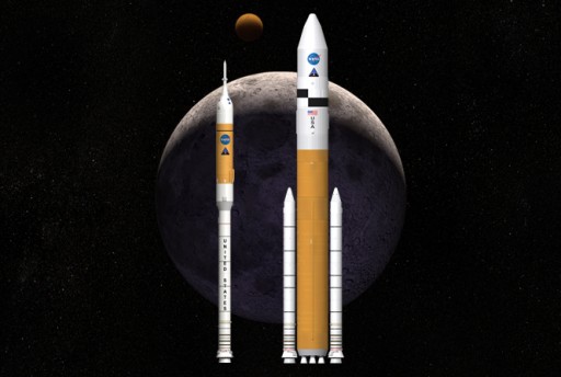
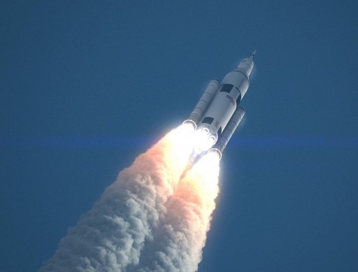
The Constellation Program was canceled in October 2010, ending all development on Ares I and V, Altair and CEV. Orion was allowed to continue development in a stripped down version known as Crew Rescue Vehicle to act as lifeboat for ISS crews. Its role in BEO missions was re-established in May 2011 when NASA announced that designs made under Constellation would be adapted for the Multi-Purpose Crew Vehicle to be flown to Space aboard the Space Launch System that was revealed in September 2011. SLS builds on the design of Ares V using extensive Space Shuttle heritage, including its engines and External Tank design to create a human-rated launch vehicle.
With Orion continuing under SLS, NASA and Lockheed Martin progressed towards a final design, no longer bound to the tight mass requirements of Ares I.
Testing of Orion started at a component level very early in the program, still under Constellation. Thermal vacuum and environmental testing of spacecraft components began at NASA’s Glenn Research Center back in 2007 in parallel with Parachute System tests picking up the same year followed by the initiation of full scale testing of the Launch Abort System in 2009 and recovery testing at sea picking up in 2009 as well.
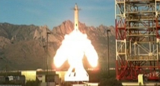
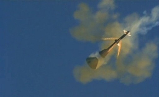
In 2010, Orion completed a Pad Abort Test that demonstrated the capabilities of the Launch Abort System and the vehicle’s parachutes to achieve a safe crew evacuation in the event of a major launch vehicle failure on the pad or during the first seconds of flight.
A number of Orion Test Articles have been built for the various test programs including a Ground Test Article used for vibration testing and as a Service Module simulator. The GTA was built at the Michoud Assembly Facility and joined the Launch Abort System at the Lockheed Martin Reverberant Acoustics Lab for acoustic testing. A second Orion Test Vehicle completed splashdown testing at NASA Langley in 2011 and 2012.
Testing of Orion’s parachute system involved Drop Test Articles and Parachute Test Vehicles 1 and 2, some of which are no longer in existence after test failures 2007, 2008 and 2010. A Parachute Compartment Drop Test Vehicle began drop tests in 2012.
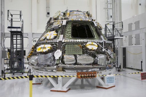
The first Orion spacecraft was delivered to the Kennedy Space Center in 2012. Just an empty pressure shell, the vehicle had all its external and internal systems installed over a two-year period to prepare for the program’s first test flight – Exploration Flight Test 1 set for late 2014.
