
 Instrument Information
Optical Design
Using Optics in X-Ray telescopes is a relatively new technology as X-Rays can only be reflected at grazing angles while conventional mirrors would absorb X-Rays. Reflective elements and optics for focusing and imaging X-Ray Radiation were first invented by German scientist Hans Wolter in 1952. Wolter Type I optical designs have been used widely for astrophysical purposes and have flown on several previous mission for example ROSAT that conducted an all-sky survey of X-Ray sources in the 1990s.
Wolter I Mirrors reflect X-Rays twice – once off an upper mirror that is parabolic in shape and a second time off a lower mirror shaped as a hyperbola. X-Rays can only be reflected at certain angles so that the mirrors are almost parallel to the incoming radiation beams. This technique allows X-Rays to be reflected without a high degree of absorption. These shallow angles cause a very small collection area per surface, so that shells of varying size are nested tightly together are required to fill be aperture. Aboard NuSTAR are two optics units, each pointing at the same are in the sky providing an increased collecting area and more sensitive images. Co-adding of the images is done on the ground during data processing.
NuSTAR’s mirrors are coated with depth-graded multilayers that are ultra-thin coatings of two alternating materials that are deposited one on top of the other. A total of 200 pairs of coatings are required to achieve a depth-graded multilayer. A high density contrast between the alternating metals is needed to reach the maximum amount of reflectivity. Common high-density materials are Tungsten and Platinum. Carbon, Silicon and Siliconcarbide are typical low-density materials. The multilayer coating acts as a crystal lattice and constructive interference creates high reflectivity for high-energy radiation. Previous Missions have flown mirrors with a single coating of Platinum, Gold or Iridium. However, these coatings begin to absorb radiation at higher energy levels and don’t reflect high energy photons to the detectors making the telescope blind for high energy radiation. Previous Spacecraft mapping X-Rays were sensitive to Radiation of up to 15keV while NuSTAR with its Platinum/Siliconcarbide and Tungsten/Silicon Mirrors will be sensitive to radiation up to 79keV. Above this energy, Platinum starts to absorb photons. NuSTAR is the first focusing telescope that is sensitive to these energy ranges.
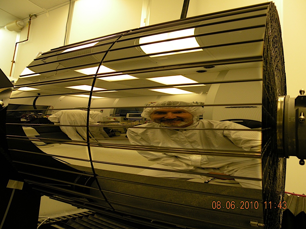
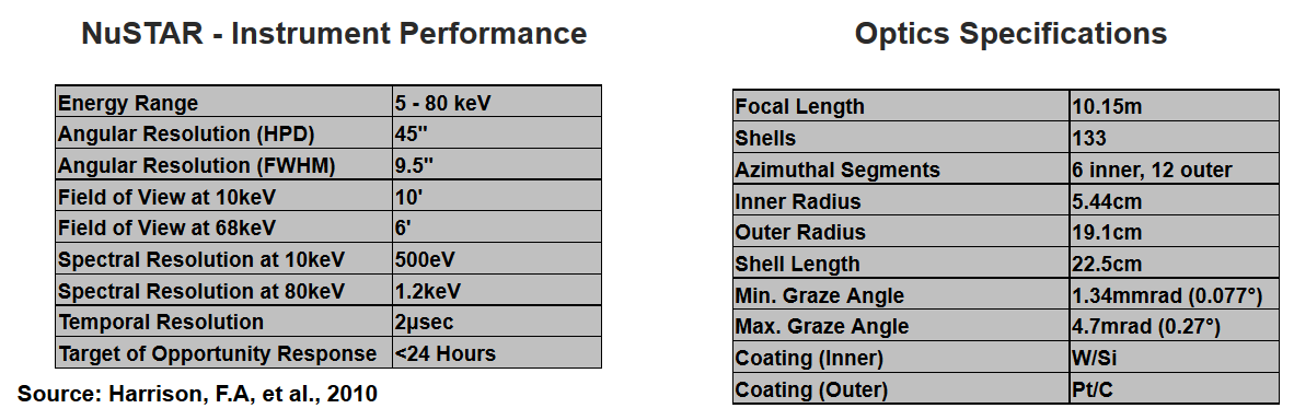
NuSTAR uses a Wolter I design comprised of 133 concentric mirror shells coated with Pt/SiC and W/Si multilayers. The optics have an overall length of 430mm, a maximum radius of 191mm and a focal length of 10.15 meters. Graze Angles of 4.6 to 16 arcminutes are provided by the optics system. The Spacecraft utilizes a light-weight design. The optics were built from the inside out with individual shells separated b Graphite Spacers held together by epoxy. Each optical unit weighs 37 Kilograms.
Detectors
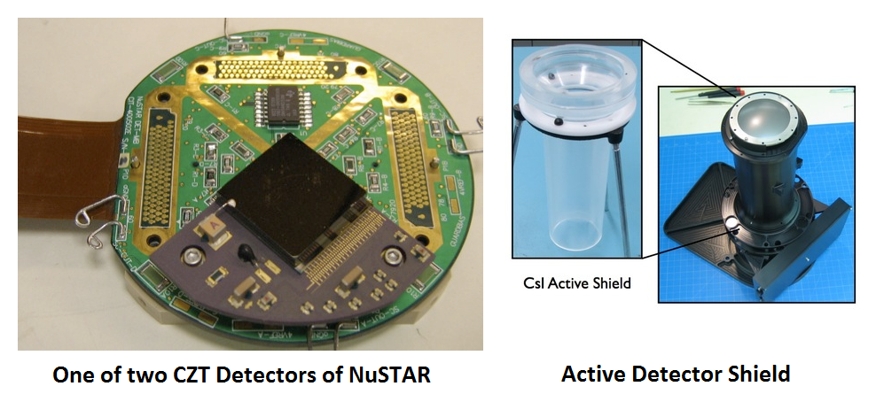
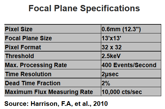 NuSTAR is equipped with two detector units, each at the focus of the Spacecraft’s two co-aligned optics units. The two optical units and detectors survey the same area of the sky and produce images that are combined on the ground as part of nominal data processing. The focal planes consist of four 32×32 pixel Cadmium-Zinc-Tellurium detectors. Each pixel is 600 micrometers in length. CZT detectors are room temperature semi-conductors that are very efficient at turning high-energy photons into electrons to visualize radiation. The electrons are digitally recorded by custom Application Specific Integrated Circuits that were specially designed for NuSTAR by Caltech. Shielding for the Focal Planes is provided by Cesium-Iodine Crystals that surround the detector housings that extend 20cm above the detector. Each shield is 2cm thick. These shields register high-energy photons and cosmic rays which cross the focal plane and are not traveling along the optical axis of NuSTAR. These events are presenting the primary background for NuSTAR and have to be identified in order to be subtracted to identify high-energy photons from cosmic sources that are being examined. CZT Detector Events that coincide with active shield events are ignored by the System that accurately distinguishes noise from actual readings. Up to 400 events per second can be registered by the detector, its associated hardware and software. In Flight, the detectors will be thermally regulated by a passive cooling system to maintain operating temperatures of 0 to 5° Celsius.
Deployable Mast
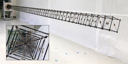
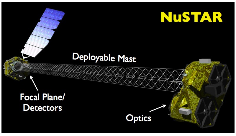
To accommodate the massive focal length of the optical suite and be as small as possible for launch, NuSTAR contains a deployable mast that deploys once the spacecraft is in orbit. Previous missions have launched in their deployed configuration making them more expensive and limiting their imaging capabilities. Long focal lengths are required to focus radiation in the X-Ray portion of the spectrum. The optics have to be several meters away from the detectors to increase sensitivity. NuSTAR has to fit on the small Pegasus Launch Vehicle as it is only a small Explorer Mission with lower budgets. At launch, the Spacecraft will be no more than two meters long and around one meter in diameter.
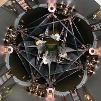
The deployable mast was built by ATK-Goleta and is a low-weight and low risk component with significant flight heritage. It provides a stiff, stable and reliable structure on which the optics of NuSTAR are mounted. To ensure that the optics are precisely aligned, an adjustment system is part of the mast. At the beginning of the orbital mission, the telescope will be aligned before starting science data acquisition. This one-time optimization of the alignment of the optical axis is provided by a mechanism making two angular adjustments as well as rotation. To measure deflections of the mast, a system is in place that uses a laser metrology system that is comprised of two lasers that are mounted on the optics and point at three light-sensing detectors at the other end of the telescope. Measurements of the laser metrology system will be used to correct the X-Ray Images that would otherwise be blurred by the motion of the mast. Deflections are caused by thermal distortions when the spacecraft passes from Earth’s shadow into the sun-lit portion of its orbit or vice versa. A star tracker is also part of the system to exactly measure deflections in order to make exact corrections.