

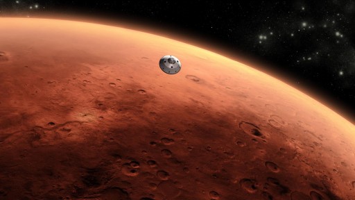
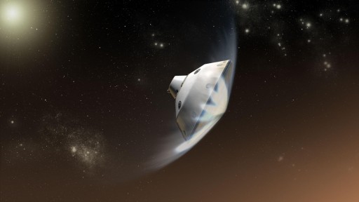
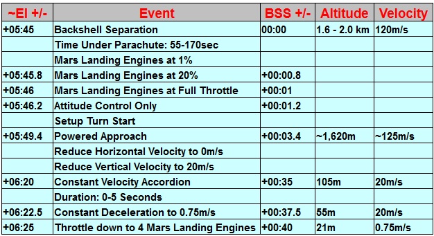
On August 6, 2012 (GMT), the Mars Science Laboratory Spacecraft will attempt a Landing on the Red Planet’s Gale Crater – making the first ever guided re-entry and Propulsive Landing on Mars – Without a doubt the most complex maneuver ever attempted in Planetary Space Flight. Entry, Descent and Landing is the term for this crucial and risky mission phase, that begins when the Spacecraft is about to hit the Martian Atmosphere and ends when the Curiosity Rover is standing on the surface of Mars – going from 21,000 Kilometers per Hour (13,000 Miles per Hour) to Zero in just under seven minutes. These will be ‘Curiosity’s 7 Minutes of Terror.’
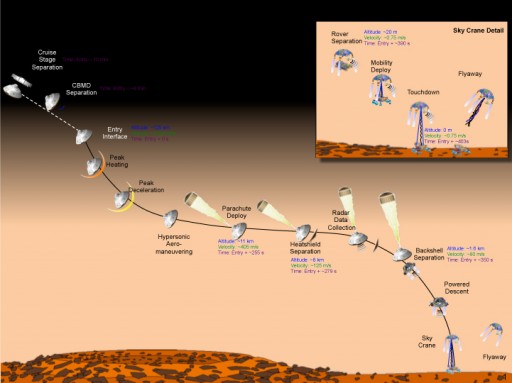
Entry, Descent & Landing Sequence Overview
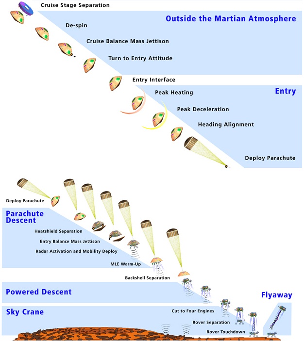
The Entry, Descent and Landing Mission Phase – short: EDL – begins when the Mars Science Laboratory (MSL) has nearly completed its 567-Million Kilometer (352-Million Mile) Trip from Earth to Mars. Having completed the launch phase (24 hours prior to launch to L+1 Day), the long Cruise Phase (207 Days and 14 Hours) and being at the end of the Mars Approach Phase (the final 45 Days leading up to EDL), the MSL Mission transitions to the EDL Phase at the Point of Cruise Stage Separation.
The Cruise Stage was needed during the Cruise Phase to control the vehicle, perform engine burns and communicate with Earth. It is separated by pyrotechnics marking the end of the Pre-Entry Phase and the start of the Exo-Atmospheric Entry Phase. At that point, the Aeroshell, the Descent Stage and the MSL Rover perform a de-spin maneuver and make a re-orientation to achieve the proper Entry Attitude. Also, the vehicle jettisons two weights to generate a Center of Gravity Offset. Entry Interface occurs at an altitude of 125 Kilometers and MSL begins a guided Entry Process going through Peak Heating and Peak Deceleration. Once the Hypersonic Aero Maneuvering Portion of the Descent is complete and the Center of Gravity Offset is eliminated, the vehicle deploys its large parachute to slow it down further.
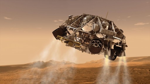
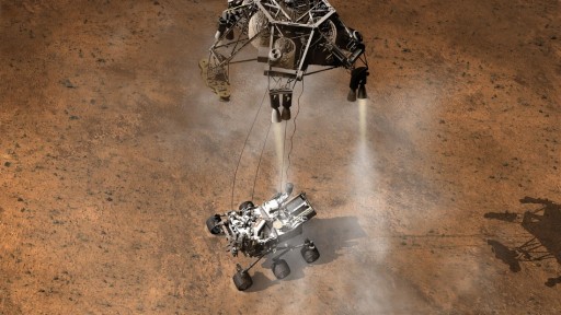
Once reaching a safe velocity, MSL drops its Heat Shield exposing the Landing Radar. Once at a Speed of 120 Meters per Second, the Descent Stage and Curiosity Rover separate from the Backshell and begin the Powered Descent Portion of the EDL Phase. The vehicle uses its Mars Landing Engines to reduce its Horizontal Velocity to Zero and make a vertical descent using its Landing Radar and slowing down to about 0.75 Meters per Second. At an Altitude of 20 Meters, the Curiosity Rover Separates from the Descent Stage and is lowered on bridles.
This Sky-Crane System is used to avoid any contamination by the Mars Landing Engines and to prevent a large dust cloud around the vehicle. While being lowered, Curiosity deploys its Mobility System (its Wheels which also function as Landing Gear). When Curiosity achieves contact with its Wheels on the surface of Mars its computers make sure that contact has indeed occurred and initiate the separation of the Descent Stage. The Descent Stage then throttles up its engines and performs a fly-away maneuver to retreat to a safe distance from the landing site for its crash landing. At that point, Curiosity is switching from its EDL Mode to the Landed Mission Mode starting Sol 0 Operations which marks the end of EDL and sets the stage for MSL’s two-year landed mission.
MSL Spacecraft and Rover – At a Glance
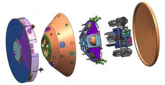
Spacecraft Components:
- Cruise Stage: Houses equipment needed for the 8.5-month Cruise to Mars such as Communications Systems, Propulsion Assets and Solar Panels. It executes Trajectory Correction Maneuvers during Cruise and Final Approach. The Cruise Stage separates before Entry when its job is done and MSL is on its final Trajectory.
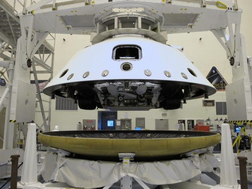
- Backshell: The Backshell is a part of the MSL Aeroshell and is outfitted with Antennas that are used during EDL, the parachute and its mortar deployment system and Reaction Control System Thrusters that control the vehicle’s orientation during atmospheric entry. The Backshell also holds ballast weights that are jettisoned over the course of EDL.
- Heat-Shield: The Heat Shield is the second part of the MSL Aeroshell. It is equipped with a PICA Thermal Protection System consisting of 113 different Tiles. The MEDLI Instrument Suite is also installed on the Shield. During EDL, it has to withstand temperatures of up to 2,100 Degrees Celsius. The Heat Shield separates during the Descent.
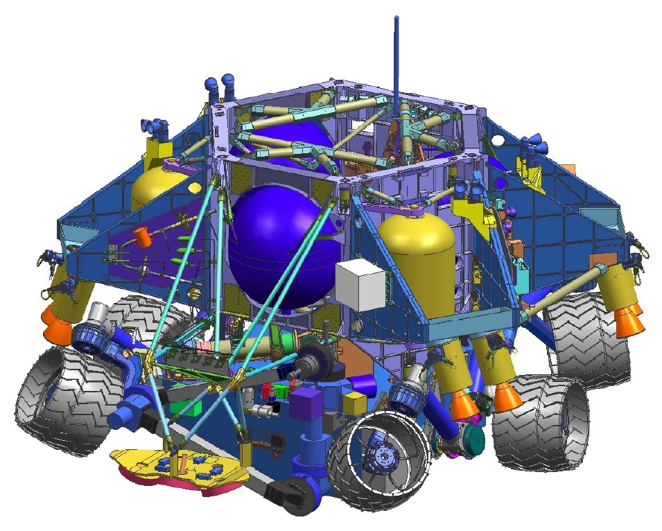
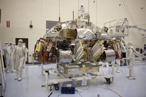
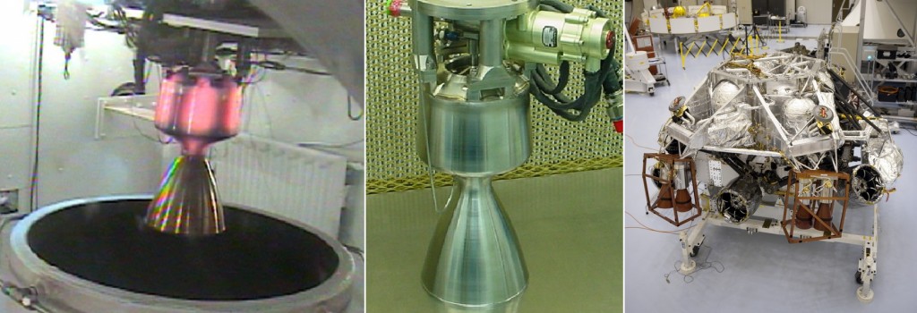
- Descent Stage: The Descent Stage is equipped with Navigation Sensors including the Terminal Descent Sensor and two Inertial Measurement Units that provide data from Cruise Stage Separation to Touchdown. It is equipped with Propellant Tanks, a Reaction Control System and eight Mars Landing Engines needed for Powered Descent.
Curiosity Rover Facts:
- Weight: 900 Kilograms
- Dimensions (Without Arm): 3.0 x 2.7 x 2.2 Meters
- Arm Reach: 2.2 Meters
- Wheels: 6
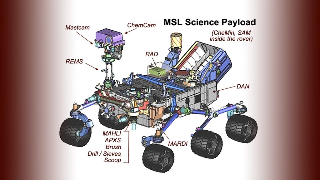
- Instruments: 10
- Cameras: MastCam, MARDI, MAHLI
- Major Components: Warm Electronics Box, Computers and Memory Avionics Boxes, Inertial Measurement Unit, Remote Sensing Mast, Robotic Arm, Mobility System, Heat Rejection System
- Power Generation: Multi Mission Radioisotope Thermoelectric Generator, 125W
- Traverse Speed: 90 Meters per Hour (max)
- Mission Duration: 668 Sols (686 Earth Days)
- Mission: “To search areas of Mars for past or present conditions favorable for life, and conditions capable of preserving a record of life.”
MSL Landing Site
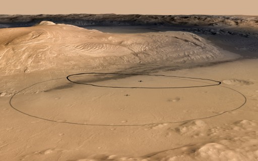
NASA’s Curiosity Rover is planned to land inside Gale Crater targeting a 6.4 by 19.3-Kilometer Landing Ellipse on the base of Mount Sharp, a 5.5-Kilometer hill in the center of the Crater. Mount Sharp is MSL’s primary science target. The Rover targets an area of flat terrain for its landing and moves to its first science targets shortly after landing. Gale is believed to be 3.5 to 3.8 billion years old. The crater has a span of 154 Kilometers. An unusual feature of Gale that played a large role in its selection is an enormous mound of debris that is slightly taller than the southern rim of the crater itself. This material is expected to have a history of 2 billion years conserving a large record of Martian Evolution, both geologically and atmospherically. Through the mound’s layers, a number of channels track along which are the features that have formed most recently. These channels are up to 250 meters deep and 2 Kilometers from side to side presenting different layers on orbiter photography. These channels might offer a chance to explore the past of the Planet’s evolution. The channel is lower and lies on a gently sloping pile the are suspected to have washed down the channel.
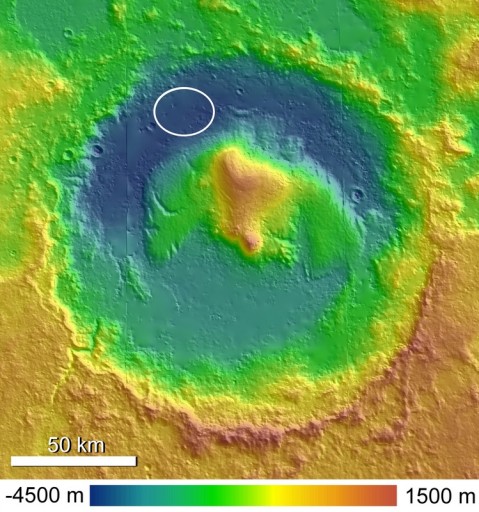
MSL traverses to Mount Sharp from its Landing Site in order to start operations. Moving the landing target as close as possible to the mountain, but still keeping error rates in mind, cuts about 6 Kilometers of traverse time. Engineers determined that MSL’s Attitude Control System was working better than expected, narrowing the original 20 by 25-Kilometer Ellipse down to 6.4 by 19.4 km. A landing 6 Kilometers closer to this target would eliminate 4 months of traverses across the base of the Crater increasing the time that can be spent with science operations. Gale holds a diversity of features and layers for investigating changing environmental conditions which will provide extensive information on the Planet’s habitability, past, present and future.
The landing site selection process for MSL occurred from 2006 to 2011 and included numerous proposals and workshops. Over 60 potential landing sites were considered and eventually narrowed down to a list of four. The final landing site was announced after the final workshop and when analyses by the MSL mission team were complete. The MSL rover was designed without a particular landing site in mind so that the rover can access more of the Martian Surface. The vehicle can tolerate a broader spectrum in environmental conditions and the process of selecting a landing site could be extended and occur later in the mission design procedure.
Detailed EDL Description
EDL Phases
-
Image: NASA – JPL – Caltech Final Approach Phase: From Entry -5 Days to Entry Interface-2 Hours
- Pre-Entry: From EI-2 Hours to EI-15 Minutes
- Exo-Atmospheric Entry: From EI-15 Minutes to the Point of Entry Interface
- Atmospheric Entry: From EI to Parachute Deployment
- Supersonic Parachute Descent: From Parachute Opening to Backshell Separation
- Powered Descent: From BSS to Rover Separation
- Sky Crane: From Rover Separation to Touchdown Detection
- Fly-Away: From TD to Descent Stage Impact
Final Approach and Pre-Entry
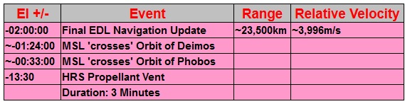
The last 5 Days of the MSL Mars Approach Phase are considered to be the Final Approach Phase that ends at EI (Entry Interface). The appropriate Flight Software for the EDL Process will have been loaded into the vehicle’s computers well before the Final Approach Phase, but the final Navigation Updates will be sent to MSL during this mission Phase. During Final Approach, Deep Space Network Coverage increases to obtain more detailed navigation data. Data used for navigation analysis includes two-way doppler tracking, two-way ranging and Delta Differential One-Way Range Determination (DDOR). Navigation data is used to precisely calculate the Entry Interface Point of the MSL Vehicle. The exact EI Position has to be correct for MSL to reach its landing site. Up to three Trajectory Correction Maneuvers are available to the Vehicle to adjust its path in order to fine-tune the exact point of Entry Interface.
One of these maneuvers is a nominally planned Engine Burn that occurs on EDL-2 Days. The other two maneuvers are placeholders for Contingency TCMs at EDL-1 Day and EDL-9 Hours. 120 Minutes prior to EDL, the final Navigation Data Update is sent to the MSL Spacecraft. This update includes MSL’s exact position at EI-9 Minutes. The Flight Computers will use this information and modify it based on measurements taken by its own navigation sensors such as Inertial Measurement Units from that point on to create a real time navigation profile that is essential for all upcoming navigation tasks until acquisition of Landing Radar Data after Heatshield Jettison.
Exo-Atmospheric Entry
This EDL Phase begins 15 Minutes ahead of Entry Interface and ends at the Point of EI which is defined as a position at a radius of 3522.2 Kilometers. 15 Minutes prior to EDL, the Flight Control System issues the ‘Do EDL’ Command which initiates the Transition to EDL Mode from the previously used ‘Do PEDL’ Mode.
Shortly after EDL Initiation, about 13.5 Minutes prior to EI, the Cruise Stage vents its Heat Rejection System. Exactly 10 Minutes before Entry Interface, the Cruise Stage is jettisoned by initiating 10 pyrotechnic devices that physically separate the the Cruise Stage from the Backshell. (More about the Cruise Stage can be found here.) Immediately after Cruise Stage Separation, the MEDLI Instrumentation Suite is enabled. The MSL EDL (Entry, Decent and Landing) Instrument suite is a set of engineering sensors and electronics to measure atmospheric properties and heat shield performance during the crucial Entry and Landing Phase of the MSL Mission.
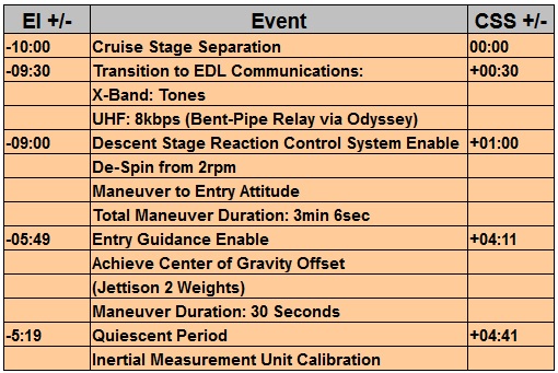
At EI-9 Minutes, the Rover Guidance, Navigation and Control System is activated and begins a series of maneuvers lasting 3 Minutes and 6 Seconds to place the Entry Vehicle in its Entry Orientation. MSL performs a De-Spin Maneuver reducing the rotation of the vehicle from 2rpm to zero. The spacecraft was spin-stabilized during its cruise phase, but for EDL, the vehicle has to be in a configuration without any rotation.
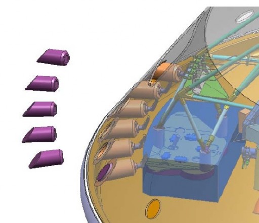
To generate a Center of Gravity Offset, two 75-Kilogram solid Tungsten Weights mounted on the outer area of the Aeroshell are jettisoned. With a perfectly centered vehicle, a guided re-entry would be impossible since there is no chance of generating any lift, but for the Cruise Phase and its maneuvers, the Center of Gravity had to be along the spin-axis so that the vehicle could ‘fly’ smoothly. The two weights are separated by pyrotechnics. This produces a lift-to-drag ratio of 0.24 at a Velocity of Mach 24 and results in an angle of attack of around 18 degrees.
This angle creates the lift necessary to fly a guided entry and the making small maneuvers, the angle can be controlled from 16-20 degrees in order to constantly modify the flight profile based on real-time navigation data. With the two weights jettisoned, MSL is enabled to make its final Pre-EI Maneuver, using the Descent Stage Reaction Control System to dampen any transients. At EI-5:19, a so called ‘Quiescent Period’ begins.
During this time, the Spacecraft makes no maneuvers and calibrates its Inertial Measurement Units. The MSL Descent Stage is outfitted with two IMUs that are the primary Source of Navigation Data during the Atmospheric Entry Portion of the Flight.
Atmospheric Entry
This portion of the Mission begins at the Point of Entry Interface and ends with Parachute Deployment. The Atmospheric Entry itself consists of four different phases.
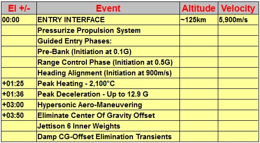
Once reaching and detecting Entry Interface, the Guidance System is switched to Entry Mode and the Reaction Control System is Pressurized. As soon as Entry begins, Guidance Computers start to modulate the lift vector by rotating the vehicle to achieve the required angle of attack to reach the desired downrange and cross range target for Parachute Deployment. The Entry Controller of the vehicle generates roll, pitch and yaw torque commands based on real-time navigation data. These commands are translated to on/off commands for the Reaction Control System that consists of eight thrusters installed in pairs outside the aeroshell. At the Point of Entry Interface, MSL is at an Altitude of 125 Kilometers above the Martian Surface (131.1km above Gale Crater) traveling at a velocity of 5,900 meters per second.
Once Entry Guidance is active, the Guided Entry Portion of the Process begins with MSL holding its pre-bank attitude until sensing 0.5G (Earth Gs). This marks the start of the Range Control Phase during which the bank angle is modified in a way to minimize the predicted downrange error at parachute deployment. Bank reversals are conducted as required with cross-range error margins being maintained at a manageable level. During this Guidance Phase, MSL experiences Peak Heating at about EI+85 Seconds.
At that point, the PICA Heatshield of the vehicle has to withstand a thermal load of more than 5,700J/cm² with a Turbulent Air Flow around the Entry Vehicle. Peak Heat Rate will be greater than 200W/cm². Eleven Seconds after Peak Heating, the Vehicle passes Maximum Deceleration experiencing a G Force of approximately 12.9. Once MSL’s Velocity drops below 900m/s, the Heading Alignment Phase of the EDL Process starts. Residual Cross-Range Error is minimized during this phase with bank angles being adjusted so that the vehicle achieves a direct-flyover of the Parachute Deploy Target.
Approximately 15 Seconds prior to Parachute Deployment at about EI+230 Seconds, six 25-Kilogram weights mounted on the inner portion of the Aeroshell are jettisoned with two-second intervals to eliminate the Center of Gravity Offset. This maneuver is known as SUFR – Straighten Up and Fly Right. Also part of the maneuver is a 180-degree azimuth turn of the vehicle to align the Terminal Descent Sensor for proper Ground Acquisition. SUFR is velocity triggered. Transients occurring due to SUFR will be dampened by the Reaction Control System and the Angle of Attack will be reduced to nearly zero.
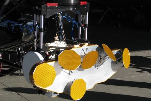
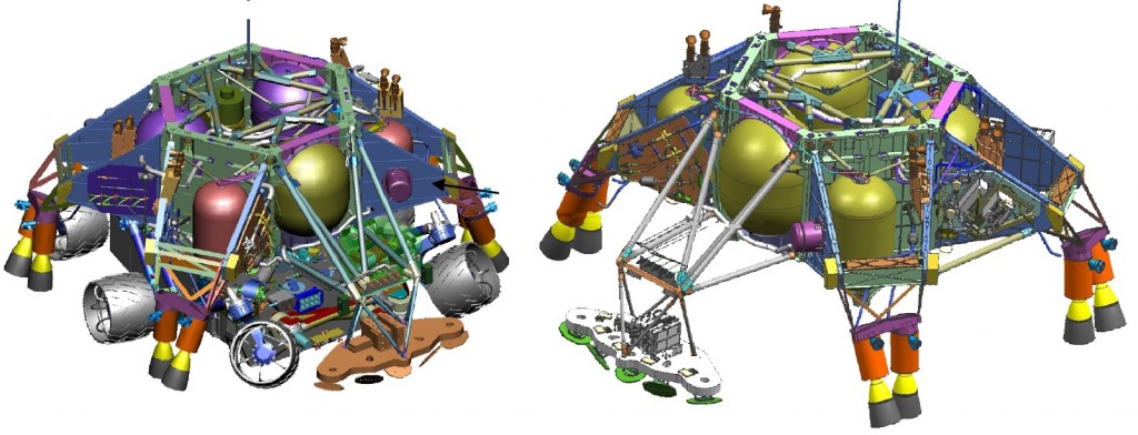
Descent Stage & Rover Configuration inside Aeroshell
MEDLI – MSL EDL Instrument Suite
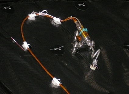
The MSL EDL (Entry, Decent and Landing) Instrument suite is a set of engineering sensors and electronics to measure atmospheric properties and heat shield performance during the crucial Entry and Landing Phase of the MSL Mission. It is not a part of the core science payload of MSL. Its goals are to provide information to help the improvement of systems that will be used on future planetary missions. MEDLI was designed, developed and built by NASA’s Langley Research Center and NASA Ames Research Center.
MEDLI includes 7 MEDLI Integrated Sensor Plugs (MISPs) and 7 Mars Atmospheric Data System (MEADS) Pressure Sensors that are installed on the heat shield of the spacecraft. Inside the heat shield and not exposed to the entry environment is the Sensor Support Electronics (SSE) Unit. It provides power, signal conditioning and signal conversion for digital processing. Data acquisition is initiated when the entry system separated from the spacecraft bus approximately 10 minutes prior to entry. It will be taking data at a frequency of 8 Hz until after the main chute is deployed about two minutes after entry interface. A portion of MEDLI data will be included in the real time telemetry stream during the entry phase. The full data set that is collected is sent to the Rover Compute Element for storage and downlink. It is expected that the complete data collection will be downliked during the first month of landed operations should downlink time be available.
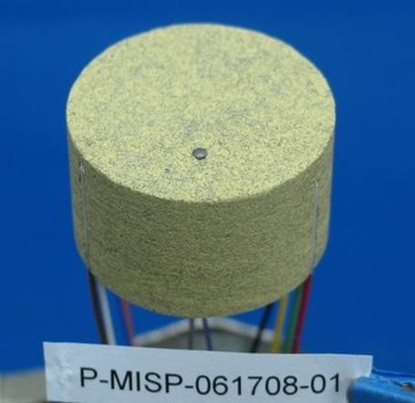
Each MISP plug consists of four type-K thermocouplers that are installed at different depths in the Thermal Protection Material of the Heat Shield to measure the heat profile inside the TPS. The couplers are installed at depths of 0.1, 0.2, 0.45 and 0.7 inches. These instruments measure the temperature of the TPS as a function of time during entry. Each plug also contains a single Hollow Aerothermal Ablation and Temperature (HEAT) Sensor. This particular sensor measures the propagation of a single isotherm through the material. Data of both instrument types will provide an exact history of the performance of the MSL TPS. The nominal data frequency is 8Hz, but some sensors will gather data at 2Hz. HEAT will also determine a loss in surface material due to ablation as a function of time during entry. The MISP plugs are concentrated in the area of the highest thermal loads due to turbulent air flow. 1.30 inches in diameter, the plugs are enclosed in the same material that is utilized on the TPS and inserted into 1.31-inch holes in the heat shield. Smaller holes are drilled through the aeroshell structure to direct the wires of the plugs to the SSE. The seven MEADS sensors include a pressure sensor that is installed on the interior of the heat shield. A small 0.1-inch hole is drilled through the TPS to allow accurate surface pressure readings. These holes will not impact TPS performance during entry. MEADS sensors form a cross pattern in the low-heating – high pressure portion of the aeroshell. This pattern will enable scientists to deduce exact vehicle orientation data from comparing MEADS data to predicted values.
SSE on Vibration Isolators

Objectives
It is anticipated that MSL will enter the Martian Atmosphere at a velocity of 6.1m/s. In combination with its size and mass, the air flow around the vehicle will become turbulent fairly early into re-entry. Heat flux and shear stress on the Thermal Protection System will be greater than on any previous Mars Mission. Uncertainties in simulations prompted large margins in the design of MSL’s heat shield at the cost of mass and science payloads. Reducing these margins for future missions requires more accurate simulations based on actual data obtained in the entry environment. MEDLI will provide data concerned with atmospheric properties and heat shield performance that will be compared with pre-flight predictions to evaluate the level of uncertainty and the margins used for this mission. MEDLI’s data collection will be the largest set of data acquired in a non-Earth Entry. Inertial Measurement Unit Data of the entry phase will be combined with MEDLI information to provide data on surface pressure distribution, vehicle attitude, dynamic pressure on the structure, Velocity, and the atmospheric density and winds. With MEDLI data, peak heat flux, distribution of heating on the heat shield, map transition to turbulence, and TPS performance will be acquired.
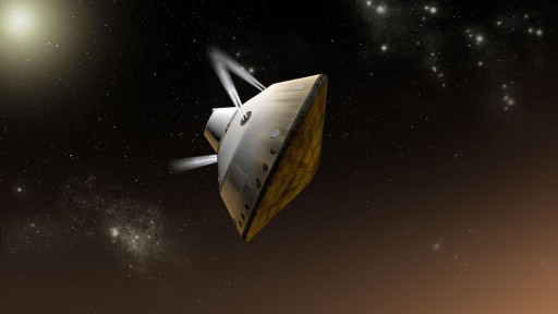
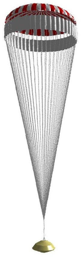
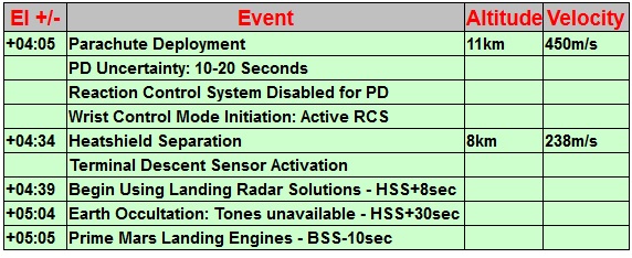
Supersonic Parachute Descent
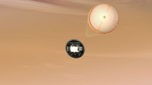
The Parachute of the Vehicle features a Velocity triggered deployment with PD occurring when a Relative (navigated) Speed of 450 meters per second is detected by the Guidance System. This speed will be achieved at an altitude of about 11 Kilometers above the surface of Mars and the biggest of the 76 pyrotechnic devices that are used during EDL will be fired. To deploy the 19.7-meter Disk Chute at a navigated speed equivalent to Mach 2, a mortar deployment system with the power of a stick of dynamite is necessary. The Chute can be opened at velocities of Mach 1.8 to 2.2 to allow some margin for unpredicted Entry Events. The Parachute burns off 95% of the remaining kinetic energy of MSL in just 55 to 170 Seconds (depending on atmospheric conditions) decelerating the vehicle from 450 to 100 m/s generating a drag force of up to 289 Kilonewtons. The parachute has 80 suspension lines with a length of more than 50 meters.
A major concern for Parachute Descent is a possible oscillatory behavior of the vehicle suspended underneath the parachute. This phenomenon has been observed on previous missions and is of importance for this flight due to MSL’s increased PD Velocity and the mass of the Entry Vehicle. Large loads of energy could be transferred to the capsule causing rotation underneath the Parachute around the Center of Gravity. A wrist mode dampening mechanism has been implemented for MSL using its Reaction Control System to reduce wrist mode frequencies to acceptable levels when limits are exceeded. Keeping the vehicle stable also ensures a safe Heatshield Jettison. As the Parachute decelerates the Vehicle quickly from transonic to subsonic conditions, MSL completes a rapid list of preparations for powered descent. The first of those is the Separation of the Heatshield to expose the stowed Rover and the Descent Stage to free-stream conditions.
The heat shield is jettisoned by pyrotechnics. Heatshield separation has to fulfill two objectives, the first being a clean separation without re-contacting the descending Entry Vehicle and second being a separation without obscuring more than one beam of the Terminal Descent Sensor – MSL’s Landing Radar and primary Navigation Sensor from that point onwards.
The first objective is met by jettisoning the Shield at a point at which there is a sufficient difference in the ballistic coefficients of the Heatshield and the Entry Vehicle ensuring that a positive separation velocity is achieved. For that, an accurate Velocity Trigger is used to initiate Heat Shield Separation at a max speed of Mach 0.7. (Using IMU Navigation makes it hard to measure exact velocities and Flight Computers rely on Navigated Velocities until the moment of TDS acquisition.) At the point of Heatshield Jettison, the MARDI Instrument becomes active (refer to the section below). With the Heat Shield out of the way, the TDS (Terminal Descent Sensor) could begin to collect data immediately after release, but it could receive false data by acquiring the heat shield instead of the ground with more than one of its beams.
The minimum distance of the Heatshield for TDS activation is 17 meters and the shield is expected to cover that distance relative to the Entry Vehicle in about 8 Seconds. An 8-second delay has therefore been implemented into the TDS Activation Sequence making sure at least 5 beams will acquire the ground. The Vehicle will take data for about 30 seconds measuring its speed with a 3-axis Doppler Velocimeter and calculating its altitude with a Slant Range Altimeter. At that point, a velocity trigger will initiate Backshell Separation. Just before Backshell Separation, the 8 Mars Landing Engines are primed by opening fuel valves with 8 pyrotechnic devices to allow fuel to flow to the engines which will start up at 1% Thrust prior to Backshell Separation.
MARDI – Mars Descent Imager
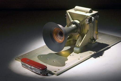
MARDI is a fixed focus full color camera fixed-body-mounted to the fore-port-side of the Rover. Its optical axis points in the +Z direction toward the ground. The camera will take high resolution images during the rover’s final descent to the Martian Surface. It will be active between heat shield separation until a few seconds after touchdown taking 5 images per second over a period of about 2 minutes. The images will be 1600×1200 pixel in resolution. Activation of the camera is done by the rover software which will send a start imaging command, the camera will operate autonomously writing data into the permanent flash memory in real time during acquisition before receiving a stop imaging command from the rover’s software when is has detected a successful landing. Image downlink will be performed later when communications and time are available.
The field of view of the detector is providing a 70° x 55° frame with the long axis transverse to the direction of motion. At a range of 2 Kilometers in altitude, the resolution will be about 1.5m per pixel, at 2m it will be 1.5mm. Over the detector is a Bayer RGB filter.
An exposure time of 1.3 milliseconds will be used and it is expected that many images will be blurred despite the short exposure due to vibrations when the landing engines are firing and angular rate motions while the rover is on the parachute.
8 Gigabytes of internal buffer are available. This enables the camera to acquire 4,000 images which is the equivalent to 800 seconds of descent with actual descent lasting only 120 seconds. The photos will be stored in raw data formats however, real time compression (lossless and lossy JPEG) is available. Small Thumbnail images will be generated prior to downlink to make the process of selecting images to downlink easier.
MARDI’s objectives include determining the exact landing spot on Mars and providing a geological&engineering framework of the landing site that will help decide on the first targets on Mars and possible transition paths. Vehicle Horizontal offsets between images within the descent sequence may be applicable to generating a digital elevation model. Additionally, ground referenced motion deviations from inertial measurement unit positioning during descent will be examined by using the images in order to extract lower boundary layer winds and to help in the development process for future automated landings and hazard avoidance systems.
Powered Descent
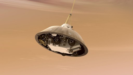
The Powered Descent Portion of the Flight begins with Backshell Separation and ends when the Curiosity Rover initiates the Sky Crane Process.
Backshell Separation occurs at a velocity of 120 Meters per Second at an altitude of 1600 to 2000 meters above Ground Level as detected by the TDS Sensor. This sensor is capable of measuring terrain relative velocity with high precision utilizing pulse doppler radar. Six independent beams (3 beams canted 20 deg. Off nadir, 2 beams canted 50 deg. Off nadir, and one nadir beam) which provide range and velocity data for the area below the vehicle so that an exact landing zone profile can be created in real time. Backshell Separation is initiated by firing pyrotechnic separation nuts freeing the Powered Descent Vehicle (PDV).
After dropping out of the Backshell, the PDV is in a near free fall condition (except for drag and the 8 Mars Landing Engines at 1% Throttle). This free fall increases velocity to about 125 Meters per Second and creates enough separation between the descending Backshell and the PDV. After 0.8 Seconds of free falling, the eight Mars Landing Engines are warmed up by throttling up to 20% for 0.2 Seconds after which the Engines are ready for operation. 2.2 Seconds of Attitude Rate Dampening follows and at Backshell Separation +3.4 seconds, the first Phase of the Powered Descent Process begins.
The PDV follows a 3-D polynomial trajectory that is generated at the point of Backshell Separation. The Powered Descent has two objectives, the achievement of the proper altitude and velocity for the Sky Crane Phase to start, and the separation from the Parachute and Backshell that can not land in the same area as the Rover. The Powered Approach follows its polynomial trajectory and brings the PDV’s Horizontal Velocity down to zero in a smooth fashion. Also during Powered Approach, the vehicle reduces its vertical velocity to 20m/s to set up for the Constant Velocity Accordion. The desired end point of the Powered Descent is at an altitude of 100 meters and 300 meters perpendicular to the plane of the Entry Trajectory. This 300-meter diversion is sufficient to ensure that MSL lands at a safe distance to its Backshell and Parachute which actually land before Curiosity does since the PDV is actively slowing its descent.
The Constant Velocity Accordion is implemented in the Landing Sequence due to potential errors in altitude knowledge at Backshell Separation (due to limited Time on Radar and IMU Navigation errors). At BSS, the vehicle still has a fairly large amount of horizontal velocity which causes the Terminal Descent Sensor to acquire data from an area that is not the actual landing zone which could result in deviations of +/-50 meters at the end of the Powered Descent Phase. This error is flown out at a constant vertical velocity of 20 Meters per Second. (Should the surface be 50 meters closer, the CVA will be zero. For the surface being 50 meters lower than expected, 100 meters of distance have to be covered, resulting in a 5-second CVA.)
The Constant Velocity Accordion ends at an altitude of 50 meters when the vehicle is still descending at 20 meters per second. At that point, the Constant Deceleration Phase of the Powered Descent begins. The PDV throttles all eight Mars Landing Engines up to 90% to maintain a constant deceleration level to reduce its speed from 20 meters per second to 0.75 meters per second which essentially is the landing speed of the Curiosity Rover. The Constant Deceleration Phase ends at an Altitude of 21 meters.
At that point, the Throttle Down Sequence begins. More than half of the 390 Kilograms of Descent Stage Propellants will have been consumed at that point. MSL seeks to maintain a constant Thrust to Weight Ratio which would require the eight engines to be throttled down to about 20-25%, but the MLEs are not as fuel efficient at low-thrust-levels so that four of the Engines will be switched to near Shutdown Level (1%). Also, propellant consumption margins are incredibly tight since the Descent Stage needs to save fuel for its Fly-Away Maneuver. The four active engines are operated at about 50% during the Throttle Down Sequence. Shutting down four Engines causes Attitude Disturbances that have to be corrected and 2.5 seconds are reserved to complete that operation and place the PDV in a stable position 18.6 meters above the surface to begin the Sky Crane Phase.
At a Glance: Mars Landing Engines
- Based on Viking Descent Thruster Design
- Nominal Throttle Range: 400 Newtons – 3600 Newtons
- Nominal Inlet Pressure: 600psia
- Capable of operating at Near Shutdown Level (1%)
- No closed Position of the Throttle Valve – No premature Shutdown
- Fuel Valve Opening: Pyrotechnics
- Number of Descent Stage MLEs: 8
- Accuracy: 5%
At a Glance: Terminal Descent Sensor
- Primary Navigation Sensor from the Point of Heat Shield Separation
- Provides exact Altitude and Velocity Data
- Capable of measuring Terrain Relative Velocity
- 6 independent Radar Beams: 3 beams canted 20 deg. Off nadir, 2 beams canted 50 deg. Off nadir, and one nadir beam
- Uses Ka-Band Frequency
- Pulse Doppler Radar Design
- Activation at Heatshield Jettison +8 Seconds
- Time on Radar: Time from HS+8 to BSS
- Minimum Time on Radar: 5 Seconds
- Desired Time on Radar: >10 Seconds
- Active through MSL Touchdown Detection
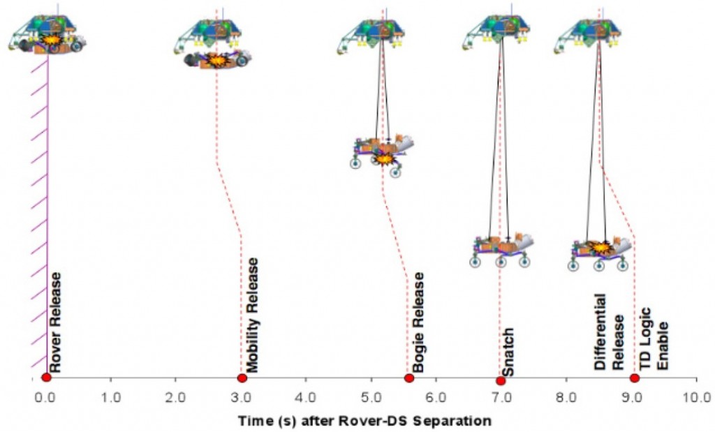
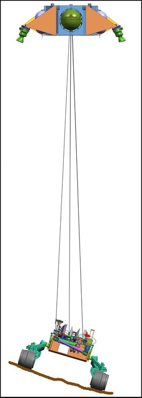
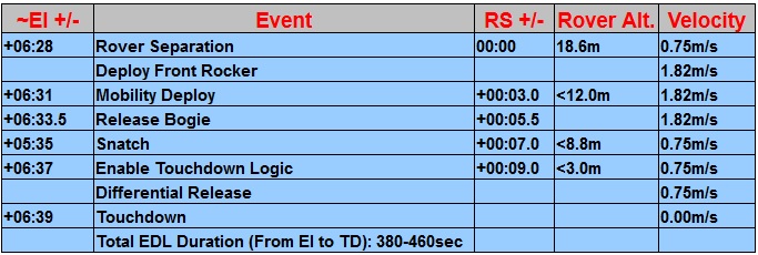
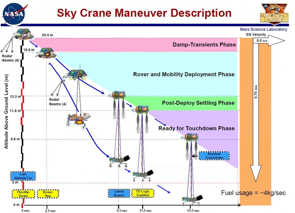
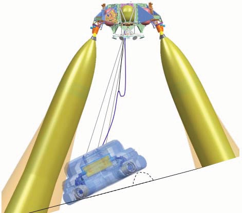
Sky Crane
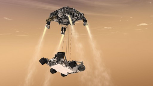
At an Altitude of 18.6 meters and a stable orientation, the Guidance, Navigation and Control System transitions to the Sky Crane Mode and initiates Rover Separation from the Descent Stage. This is expected 42.5 seconds after Backshell Separation and about 5 minutes and 45 seconds after Entry Interface.
Rover Separation is accomplished by firing pyro-separation devices. After Separation, the MSL Rover’s only structural connection to the Descent Stage is a triple bridle system with an umbilical cord providing power to the Rover and Data from the Rover to the Descent Stage and vice versa. While the Sky Crane System is in motion, the Descent Stage continues to move at a vertical velocity of 0.75 meters per second. Immediately after Rover Separation, the three nylon Bridles start to lower Curiosity. Three Seconds after Rover Separation, Curiosity starts to deploy its Mobility System – the six wheels that also function as landing gear.
Bridle and Umbilical Device
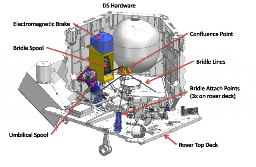
 After 7 seconds, the Bridles are fully extended at 7.5 meters and motion stops. This snatch causes attitude disturbances which need to be corrected by the Descent Stage within 2 seconds. The bridles are stopped by an electromagnetic brake that is connected to the spool that contains the bridles. All three bridles pass through the same confluence point on the Descent Stage which is nearly collocated with the vehicle’s Center of Gravity to limit any disturbances to a minimum.
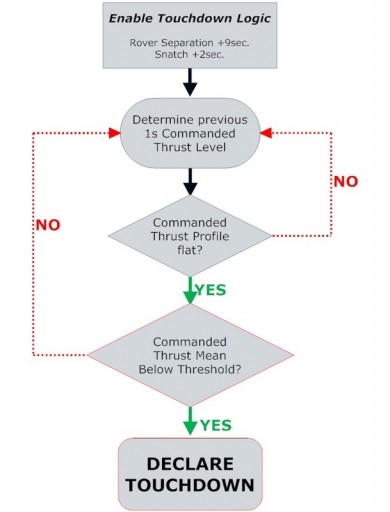
Two Seconds after the snatch, 9 seconds after Rover Separation, the Touchdown Logic is enabled (refer to the Diagram to the left). Rate of Descent remains at 0.75 meters per second and the Flight Computers monitor Thrust Levels of the four active MLEs in one-second intervals. When touchdown occurs, the Rover’s weight will be supported by the Martian Surface and the bridles will be offloaded causing the Descent Stage Thrust Level to go down. As per the Touchdown Logic, the Thrust Level has to be within a certain threshold and it needs to be a flat profile indicating that all four wheels have settled on the surface.
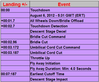
It is expected that all wheels will be down 1.7 seconds after first contact with Touchdown Detection occurring at TD+2.7 seconds. As soon as Touchdown is declared, the Bridle Cut Command is sent. It takes the pyrotechnics about 0.3 seconds from CMD to Bridle Cut. Just 0.2 seconds after the Bridle Cut Command is issued, the Umbilical Cord Cut Command will be sent and the cord is cut 0.015 seconds later. At TD+3.2 Seconds, 0.5 seconds after Touchdown Declaration, Curiosity should be on its own standing somewhere near Mount Sharp inside Gale Crater with its Descent Stage right above its head thundering to 100% throttle for the Fly Away.
MSL Rover Deployment
At a Glance : MSL Descent Stage
- EDL System Weight: 2,401kg (Rover, Aeroshell, Descent Stage)
- Descent Stage Control: Descent Stage/Fly-Away Controller
- Propulsion: 8 MLEs
- Reaction Control: 8 Thrusters
- Propellant: Monomethylhydrazine
- Propellant Mass: 390kg in 4 Tanks
- Propellant Margin: ~90 Kilograms
- Navigation: 2 Inertial Measurement Units, 1 Terminal Descent Sensor
- Sky Crane: 3 Bridles – 7.5 meters, 1 Umbilical Cord for data connection
- Sky Crane Break: Electromagnetic
- Electrical System: 2 non-redundant Thermal Batteries – 27-37 Volts
- Pyro Initiation: Two Redundant 26-36V Batteries
- Pyro Power Buses: 2
- Propellant Consumption during Sky Crane: 4 Kilograms per Second
- Configurations: Cruise Configuration; Sky Crane Configuration
- End of Mission: Fly-Away and Ballistic Impact
Descent Stage – Stowed & Deployed Configuration
Fly Away
After all connections with Curiosity are cut, the Descent Stage Controller detects a successful landing sequence completion and initiates its Fly Away Mode. After assuming control over itself, the Descent Stage controlled by the Descent Stage Controller waits for 187msec hovering in position above the Rover to allow some margin for bridle and umbilical cord cut. When the waiting period is over, the Descent Stage throttles two of its Mars Landing Engines back up to 100% with the other ones throttling up to a little bit less than 100% to allow the vehicle to pitch over to about 45 degrees along the Y-axis. Once the turn duration is complete, all engines come back to 100% and the Descent Stage is on a patch away from the Landing Site. The exact duration depends on the amount of fuel that is remaining. Once all tanks are empty, the Mars Landing Engines shut down and the vehicle is on a ballistic trajectory. It impacts at a minimum distance of 150 meters to Curiosity. With the impact of the Descent Stage and the transition of the Curiosity Rover from its EDL Mode to the SOL 0 Procedures, the most complex Planetary Landing Operation ever attempted will be completed and the largest Mars Rover to date will hopefully be standing somewhere near Mount Sharp inside Gale Crater.
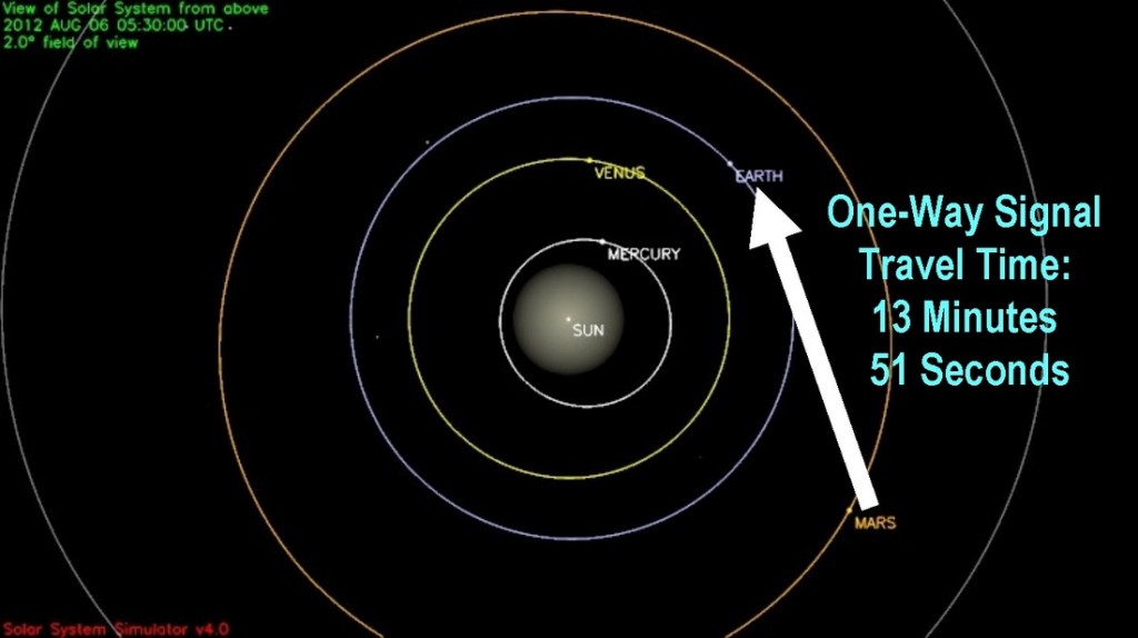
Communications Delay
On Landing Day, Mars and MSL will be 13 Minutes and 51 Seconds of Light Travel Time from Earth which is equivalent to the one-way signal travel time from the MSL Vehicle to Earth. This obviously means that there is no possibility of human intervention should anything wrong show up in the Telemetry Stream during EDL. It also means that MSL will already be on the surface of Mars – dead or alive – when we will be looking at Telemetry Data sent during the Exo-Atmospheric Entry. MSL lands at Gale Crater on August 6, 2012 at about 5:17 GMT with earliest Signal Arrival at 5:31 GMT. At the earliest, confirmation of mission success or failure will come 14 minutes after the actual landing time, although it is anticipated that it could take much longer to establish initial contact with Curiosity. (See the Entry Communications Section Below)
EDL Communications
During Pre-Entry, nominal Cruise Communications are used. The Cruise Stage provides X-Band Communication with the Deep Space Network Stations on Earth at a rate of about 500 bits per second during Pre-Entry via its Medium Gain Antenna. At the point of Cruise Stage Separation, Communications switch to the EDL Mode during which Low Gain Antennas on the Backshell, Descent Stage and Rover are used. The Backshell is equipped with a regular Low Gain Antenna and a Tilted Low Gain Antenna that is used when the nominal antenna is blocked by the Parachute. The Descent Stage is outfitted with a single Descent Low Gain Antenna that is active during powered descent. Aboard the Rover itself is a High Gain Antenna which is not used during EDL and a Low Gain Antenna that is used immediately after EDL or during final Descent should the Descent Stage Communication Assets fail.
These low gain antennas send a Direct To Earth X-Band Frequency that will be monitored by the Deep Space Network. Data sent via this link is of a very low rate and only consists of MFSK Tones also called semaphores. Each timeline segment of EDL has a unique set of nominal and off-nominal tones assigned to it. There are a total of 256 different tones that can be sent to Earth. These tones can be converted to useful information about the basic status of the vehicle and the completion of EDL Events, but can’t be considered real telemetry data.
MSL’s antennas will also provide a UHF Signal during EDL which has a data rate of up to 8kbps and includes basic vehicle telemetry that is sufficient for failure analysis, but is still no complete EDL Engineering Data Set. A UHF Antenna with 8 patch antennas is mounted on the Backshell and provides a solid data stream during EDL. The Descent Stage has a single UHF Antenna and the Rover is also outfitted with a UHF Antenna that can be used during EDL. The UHF Frequency will be picked up by the Mars Reconnaissance Orbiter and the Odyssey Orbiter as well as ESA’s Mars Express that will be attempting to record the UHF Signal. Odyssey also has the capability of directly relaying the UHF Telemetry Stream to Earth via X-Band and its more powerful antennas. UHF Relay will feature a short additional delay due to Orbiter Capabilities. ODY is the only Orbiter capable of providing bent-pipe communications. Also, the UHF data stream and the X-Band Tones could experience several drop-outs during EDL.
Loss of Signal is expected for a 1-second period at Cruise Stage Separation and the switch to the Low Gain Antennas of the Backshell during the Maneuver to the Entry Attitude. During the Peak Heating Phase, a plasma envelope forms around the MSL Vehicle that causes an UHF Blackout of 25 to 100 seconds. X-Band tones are uninterrupted at that point.
After parachute deployment, X-Band Tones are no longer received on Earth because MSL is no longer visible from Earth and its DSN Stations. Tones are sent throughout EDL, but won’t be heard since Earth will have set at the Landing Site.
UHF should be solid at that time. At the Point of Backshell Separation, Communications are changing to the Descent Stage UHF and Low Gain Antennas which are blocked by the Parachute for 1 to 6 seconds. The final expected Communications Drop Out comes at the moment of Rover Separation when UHF Communications switch to the Rover UHF Antenna. After touchdown, MSL sends a Landing Sequence Complete Signal and switches to pre-planned communication modes which involve Direct To Earth Communications and Mars Orbiter Communication Phases. All Communication windows of the initial Surface Operations Phase are loaded into the Flight Computers during the Cruise to Mars so that initial contact opportunities are not mandatory.
Confirmation of a successful Landing could reach Earth in ‘real time’ with the nearly 14-minute delay should communication angles be favorable after touchdown. In case of any blockages due to geological features (Rocks, Craters, or MSL landing on a slope facing away from Earth), confirmation of a successful touchdown could take several hours if a communications pass with one of the Orbiters is needed. About two hours after landing, Odyssey has a planned Communications Pass over Gale Crater which would be the next chance of getting a signal from the Rover after EDL Communications. Should the UHF Signal be interrupted for any reason, this is the earliest confirmation of the EDL outcome after touchdown.
ESA’s Mars Express Spacecraft relays the stored UHF data at Landing +1 to 2 Hours which is the earliest insight into EDL events not depending on Odyssey. MRO transmits stored UHT Telemetry to Earth at EDL+4 to 5 Hours. Sol1 communication passes have also been loaded into MSL’s Computers so that the vehicle could theoretically afford to miss all Communications following EDL-120 Minutes since all aspects of EDL are automated. The first HazCam images acquired by MSL after landing could reach Earth via the EDL+2-Hour ODY Pass.
Because real time telemetry is limited during EDL, the MSL Spacecraft will store a full EDL Telemetry and Engineering Data Set in its on-board memory. This data will have a rate of 100Mbit/s and include all vehicle parameters from EI-10 Minutes to Touchdown +1 Minute. This data set is downlinked to Earth during the first few Sols of Landed Operations.
Tight Margins
The Entry Sequence as described above does not include a lot of margin for any problems and unforeseen Events. Timeline Margins are not a real factor since the MSL Entry Timeline depends on several points of reference that are triggered by actual EDL parameters (Velocity and Altitude) rather than a fixed timeline.
One margin that is important for a safe EDL Process is the so called Time on Radar. This is the time period spent under the Parachute with a good Data Stream coming from the Terminal Descent Sensor. A minimum of 5 seconds of Radar Time are required to obtain an initial profile of the landing zone, but teams would prefer at least 10 seconds of Time on Radar to allow the vehicle to get a full profile of its landing zone prior to computing its Powered Descent Trajectory which occurs at the moment of Backshell Separation. Because Heat Shield Jettison and Backshell Separation are velocity and altitude triggered events, there is no real chance of confirming that the time in between the two events is sufficient. HS Separation occurs at 238 meters per second and the TDS becomes active 8 seconds after HS Jettison, but needs correct off-nadir angles to obtain valid data. Backshell Separation occurs at 120 meters per second.
In the predicted Entry Timeline, there are about 25 to 30 seconds of Time on Radar, but in actuality, this time will be shorter due to the capabilities of the Radar and a time offset generated by atmospheric conditions, so that the statistical margin goes down to 20 to 25 seconds of time of radar, but still giving a sufficient margin for a near-nominal EDL.

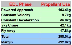
The biggest Limiting Factor of the EDL Portion of the MSL Mission is Fuel. At the point of Cruise Stage Separation, the Descent Stage starts out with 390 Kilograms of Monomethylhydrazine. During Exo-Atmospheric Entry, Propellants are used for the De-Spin Maneuver, attitude settling after Cruise Stage Separation and the Maneuver to the Entry Attitude. During Entry, the RCS System is used for Entry Guidance Maneuvers, Wrist Mode Management and propellant is consumed during Mars Lander Engine Priming. The Powered Descent consumes the largest amount of Propellants with an partly active RCS and eight burning Mars Landing Engines. After touchdown, the Descent Stage requires enough Propellant to conduct the minimum Fly-Away Maneuver of 4 seconds. Statistical Values obtained during simulations have shown that fuel margins are relatively tight. The models did not take propellant use during Exo-Atmospheric and Atmospheric Entry, Parachute Descent and MLE Priming into account and came up with a margin of about 91 Kilograms of Hydrazine. Assuming that the actual margin is somewhat lower, MSL has about 20 seconds of margin during powered Descent and Fly-Away because propellant consumption during Constant Velocity and Sky Crane Operations is 4 kilograms per second.
EDL Propellant Budget
One additional margin that is worth noting is the maximum stress the vehicle can handle. MSL’s maximum tolerable G Force during Entry is 15G. During a nominal EDL Sequence, Peak Deceleration occurs at Entry Interface +96 seconds and reaches a maximum of 11 to 12 Gs. In simulations, slightly off-nominal EDL Parameters such as an off-target Entry Interface lead to G Forces of up to 13G. The Entry Logic does not have a G Limiting feature built into it.
Touchdown margins for the MSL Rover are fairly tight as well. MSL can land with a maximum horizontal velocity of 0.5 meters per second (planned: 0m/s) and a vertical velocity of 0.85 meters per seconds (planned: 0:75m/s). The vehicle can safely land on slopes of up to 15 degrees. Steep slopes cause the potential of direct plume impingement or contamination by combustion products while the Descent Stage hovers horizontally. The worst case scenario would be MSL Landing on a 15-degree slope and a 0.55-meter tall rock. In such a case, the Rover would be in danger of suffering damage by direct exposure to MLE Plumes. In a nominal landing scenario on flat terrain, plume clearance is sufficient, even with small attitude settling maneuvers made by the Descent Stage.
Systems Redundancy is also an item with a very tight margin. There are not many systems of the entire EDL Design that provide redundancy. One of the key-elements in succeeding at a propulsive landing on Mars is weight. Adding redundancy to the system would add more weight to the vehicle and tighten other margins such as the already critical fuel consumption. For MSL’s EDL Operation to be successful, all Systems have to work 100%. All 76 pyrotechnic devices have to work at the exact millisecond they are planned to, all 8 Mars Lander Engines have to start up properly, all 3 bridles have to lower as expected and the single parachute has to open for Curiosity to arrive on Mars in one piece.
Dynamic Architecture
Many of MSL’s EDL Operations are triggered by time-stamped commands which in turn are triggered by a series of Events. These individual Events depend on parameters such as Velocity, Atmospheric Pressure and Altitude. This enables MSL to respond to dynamic conditions such as atmospheric disturbances and winds in the lower atmosphere without sticking to a fixed, pre-programmed timeline which would increase error rates. The duration of the EDL Sequence from EI to Touchdown can vary from 380 to 460 seconds depending on dynamic conditions of the Martian Atmosphere.
MSL Points of Reference:
Entry Interface: The Moment MSL encounters the first traces of the Martian Atmosphere. All Pre-EI and a number of Post-EI Events are time-triggered based on the moment of EI.
Parachute Deploy: PD is triggered by the vehicle’s Velocity and following Events depend on the timing of PD.
Heat Shield Separation: The Separation of the Heat Shield is velocity triggered to ensure the Heat Shield has a positive separation velocity as a result of a sufficient difference in ballistic coefficients. Terminal Descent Sensor activation is triggered based on the timing of HS.
Backshell Separation: This Event is one of the most important steps in the EDL Sequence. At the moment of Backshell Separation, the Flight Control System computes its powered descent trajectory that is essentially unchanged until Touchdown occurs. The initial Sequence of events after BSS is time triggered and is part of a 3.4-second operation. All other events from BSS to Rover Separation are altitude and velocity triggered.
Rover Separation: Rover Separation initiates a series of time triggered events such as the deployment of the Rover’s Mobility System and the snatch of the bridles as well as the activation of the Touchdown Logic which is a sequence with 1-second intervals that detect the actual moment of touchdown.
Touchdown: After touchdown is declared, a series of time-stamped events occurs that culminate in the initiation of the Flyaway Maneuver.
Calculated Risk
MSL’s EDL Sequence is the most complex Planetary Landing Operation ever attempted. It features tight margins and complex systems that all have to function correctly. 510,000 Lines of Code are needed for EDL. All the Entry Software has to work correctly and be executed by the associated hardware properly. However, the entire EDL Sequence is based on engineering reason and analysis, and teams are very confident that it will work, but some doubt remains since there are elements that have never been tested before. These elements include the powered descent and sky crane sequence. Tests of these key features are impossible on Earth because the environment on Mars is completely different. Individual components such as the Mars Landing Engines and the Landing Radar have been tested extensively, but the complete sequence will be executed for the first time when MSL makes its actual descent.
Initial Surface Operations
Calming down from the fast moving events from EDL, Initial Surface Operations are moving at a much slower pace. Since MSL’s primary Mission duration is much longer than that of previous Mars Rover Missions, teams can afford to take a longer time period for initial operations to make sure all set-up tasks and Rover health checks are completed satisfactory.
Immediately after landing, Curiosity switches from the EDL Mode to its Sol 0 Mode which marks the start of MSL Surface Operations. The focus of the first few hours and days on the Martian Surface will be initial Rover Checks. With the uncertainty of the timing of first contact with Earth and the large Communications Delay, the Sol 0 Operation is autonomous and Curiosity can complete these steps without contact to Earth. After touchdown, the Rover conducts a status check of all essential systems.
Temperature sensors become active and the Thermal Control System adjusts to the new environment, keeping all equipment within Red-Line Temp Limits. Also, HazCam Footage is acquired and prepared for downlink. The first larger data package is planned to be downlinked to Earth about 12 hours after landing when the Mars Reconnaissance Orbiter passes over the landing site. The first priority for the mission team is to gain understanding in the immediate surroundings of the Rover making sure that the landing zone is known and that the situation the Rover is in (Systems Status, Landing Zone, Hazards in the vicinity, etc.) is fully understood with Curiosity being in a secure configuration. Also being looked at, is the surface directly underneath and around the rover to make sure there is no immediate threat.
It could take up to five days to complete initial checks and validations. To achieve solid communications, MSL deploys its High Gain Antenna some time after landing. After that, Curiosity is given the Green Light to deploy its large Mast and Sampling System including the Robotic Arm. The navigation cameras take images of the sky to calculate the position of the sun and the High Gain Antenna is pointed towards Earth for more stable communications. After the first 5 Sols, Subsystem and Instrument checks are in progress. The first drive of the vehicle is expected about 1 week after landing. As the Science Mission gets underway, more tests of the instruments are performed before actual sampling operations can begin.
