
MSG-4 Satellite – Meteosat Second Generation
MSG-4 is the fourth satellite in the Meteosat Second Generation of spacecraft, also known as Meteosat-11 in the overall Meteosat program under operation by EUMETSAT, the European Organization for the Exploitation of Meteorological Satellites that was established in 1986 as a cooperation between European states to establish a unified European meteorology agency.
The Meteosat program finds its origin in 1977 when the first prototype satellite was launched to explore the technologies needed to acquire meteorological data from Geostationary Orbit. Two more prototype satellites were launched in 1981 and 1988 before the first operational satellite, Meteosat-4, launched in 1989. As part of the Meteosat Operational Program, three satellites were launched followed by Meteosat-7 in 1997 as part of the Meteosat Transition Program that was implemented to bridge the gap between the first and second generation of Meteosat spacecraft by launching one improved first generation satellite.
Meteosat-7 remains in operation as of 2015, becoming the longest serving operational satellite in the history of EUMETSAT. The second Meteosat generation was initiated in 1993 with a two-year science definition program before instrument and satellite development began in 1995 under split funding by ESA and EUMETSAT with ESA responsible for the development of the first of the MSG satellite and EUMETSAT in charge of financing the three remaining satellites, providing the ground and data processing system and operating the satellites.
The first second generation Meteosat made its way into orbit in August 2002 and was to be followed by three more satellites to continue an operational continuity of Meteosat data for at least 16 years. MSG-2 launched in 2005 after the first second generation satellite had finished checkouts and proved all systems and instruments were providing the expected performance. MSG-3 launched in 2012 to become Meteosat-10 once its in-orbit checkout was complete.
Since 2013, the existing Meteosat constellation has entered a mode of operations in which the operational satellites share the labor – Meteosat-7 is stationed over the Indian Ocean, responsible for the acquisition of imagery of the Indian Ocean every 30 minutes and the relay of data from buoys in the Ocean in support of the Tsunami Warning System while Meteosat-8, 9 and 10 are stationed over Africa.
Meteosat-9 delivers rapid-scan data for Europe while Meteosat-10 is in charge of full-disk imaging of Earth and Meteosat-8 is in a backup mode for either spacecraft 9 or 10. Once fully commissioned in orbit, MSG-4 (then to be re-named Meteosat-11) will be placed in a storage mode to take over from one of the older spacecraft once their performance starts degrading.
The Meteosat Second Generation Program was conceptualized as a two-satellite operational service like its predecessor. Only one satellite is required to provide the core data to fulfill the objectives of the Meteosat program. MSG delivers to the user community continuity of data services of the first Meteosat generation, but with significantly enhanced services and data products. Data delivered by MSG is used in support of weather nowcasting, very short and short-range forecasting, numerical weather forecasting models and climate monitoring over Europe and Africa.
Spacecraft Overview
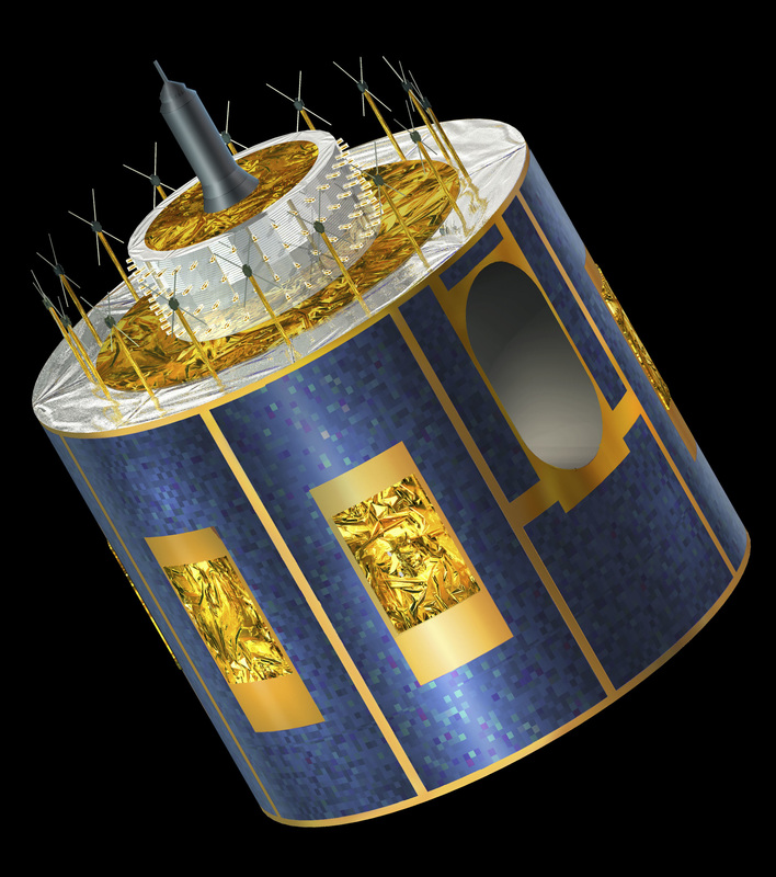
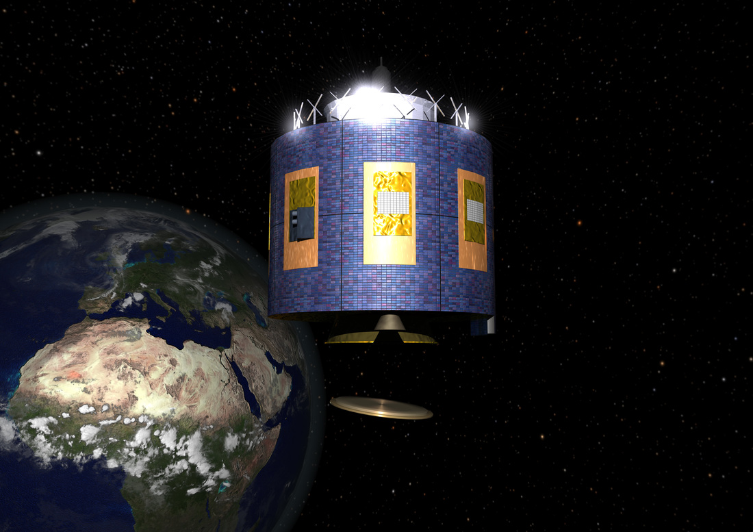
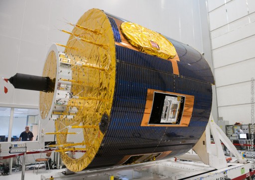
The MSG satellites – built by an industrial consortium led by Alcatel Space Industries of France – are cylindrical spacecraft that use spin stabilization, rotating their bodies at 100 revolutions per minute to remain in a stable orientation, not requiring active attitude control systems. The spacecraft body is a cylindrical solar drum that measures 3.22 meters in diameter and 3.74 meters in length with a body height of 2.4 meters using a stepped cylinder design. The MSG satellite has a mass of around two metric tons.
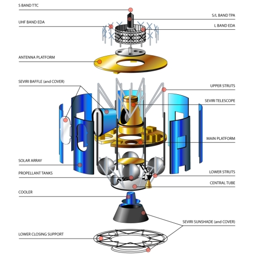
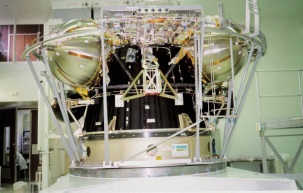
The MSG satellite structure consists of two main parts, the 192-Kilogram primary structure that provides the support of the satellite payload and the various subsystems and electronics boxes, and the Secondary Support Structure weighing 27.5 Kilograms and supporting the Unified Propulsion System and the Electrical Power System. The Primary Structure itself is comprised of the Service Module Structure hosting the payloads and majority of the subsystems, and an Antenna Platform hosting the communications antenna.
The Service Module includes a Conical Central Tube using a stringer-stiffened shell design with three interface rings to facilitate the launch vehicle adapter, the main platform and the propellant tanks. The Central Tube provides the primary mounting structure for the propulsion system. The Main Platform is fabricated from aluminum sandwich panels to build the interface with the instruments and subsystems in its aft section. Lower struts installed on the Central Tube support the outer edges of the platform and two struts support the main platform while a series of upper struts connects the Service Module to the Antenna Platform.
The Secondary Structure hosts two Liquid Apogee Motor supports each comprised of three struts to provide the engines with iso-static mounting, alignment accuracy and pointing stability. The Secondary Structure also supports two helium tanks each with one bipod and one tripod, and it supports four thruster assemblies using structural brackets.
MSG Structural Subsystem
The Electrical Power System of the MSG satellites consists of body-mounted solar panels, a pair of batteries and a power control unit. Eight solar panels are installed around the satellite body based on Carbon Fiber Reinforced Panels that hold 7854 Silicon Solar Cells, each 60 by 32 millimeters in size, delivering a maximum of 740 Watts of electrical power at the beginning of the satellite’s life and 600W at the end of the primary mission. 66 solar cells are connected in series, creating 119 solar cell strings connected in parallel.
The two Nickel-Cadmium batteries have a total capacity of 1200 Watt-hours to keep the satellite operational during eclipse periods, each has 16 series-connected cells and weighs 27.5 Kilograms. The 23.5-Kilogram Power Control Unit delivers a regulated 27-Volt power bus to the various subsystems of the satellite including the instruments and it controls the state of charge of the batteries via four charge and six discharge regulators.
Power bus protection and switching is provided by the Power Distribution System that hosts 42 current-limiting switches. The PDU also controls the vehicle heaters that are actuated by 54 transistor switches.
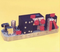
The Attitude and Orbit Control System hosts a series of sensors for the generation of attitude, nutation, spin rate and reference information. The AOCS is comprised of two major parts, the Attitude and Orbit Control Electronics Box that consists of four slices connected via a backplane to receive and process signals from the second component of the system, an Attitude Sensor Assembly hosting one internally redundant sun sensor, a three-channel Earth sensor, two accelerometer units and two Passive Nutation Dampers.
The AOCS Electronics Box receives signals from the various sensors, processes the data into reference pulses and analog data that is then transmitted to the spacecraft computer.
In addition to operating the AOCS, the electronics are also in charge of the operation of the Unified Propulsion System that includes the reaction control thrusters of the spacecraft which are the primary means of attitude control. Given the importance of the electronics, there are two boxes aboard the spacecraft, one serving as hot backup in case the primary system encounters a problem. Overall, the entire AOCS system has a mass of 16 Kilograms and requires 8 to 14.5 Watts of electrical power during operation.
The AOCS is in charge of providing a reference pulse whenever the Earth and Sun are detected by their respective sensors to allow the system to calculate the geometry of the satellite, Earth and Sun and coordinate instrument operation. During the GTO phase of the mission, the AOCS uses the accelerometers and sensors to gather nutation angle and frequency information for active nutation control delivered by the thrusters. Satellite operations are synchronized through the use of Sun and Earth Synchronization pulses.
While in the Geostationary Transfer Phase of the mission, the MSG satellite is operated in a closed-loop active nutation control using its axial reaction control thrusters to remain in a stable orientation for maneuvers and operations. Passive nutation dampening is employed once the acquisition of station in Geostationary Orbit is complete. Because the spinning satellite provides a self-stabilized attitude, it was decided to simplify onboard operations by operating the spacecraft in open-loop, ground-controlled mode in which all maneuvers including attitude, stationkeeping and spin rate adjustments are prepared on the ground and commanded via ground stations.
Overall, the AOCS can measure the satellite spin rate with an accuracy of 0.01RPM, the spin axis orientation by 0.1 degrees and the nutation by 0.03 degrees.
The MSG satellites use a Unified Propulsion System, meaning that the Main Propulsion System and the Reaction Control Thrusters are fed from the same tanks. This differs from the first generation of Meteosat spacecraft that featured solid-fueled boost modules to inject themselves into Geostationary Orbit while a small hydrazine-fueled system provided fine-orbit control and attitude actuation. MSG is the first satellite to host a Unified Propulsion System on a spinning satellite rotating at 100RPM.
The MSG satellites feature a bi-propellant propulsion system using Monomethylhydrazine as fuel and Mixed Oxides of Nitrogen (MON-1) as oxidizer stored in four spherical tanks with a diameter of 75 centimeters holding a total propellant mass of up to 976 Kilograms. 83% of propellants will be consumed for the transit from Geostationary Transfer Orbit to the desired position in Geostationary Orbit while 11% will be consumed over the seven-year mission for inclination and spin-rate control and 4% will be used for east-west stationkeeping. Without propellants, the Unified Propulsion System has a mass of 94 Kilograms.
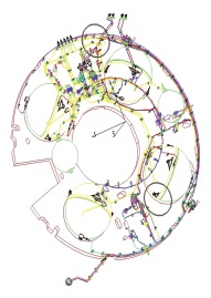
The Unified Propulsion System is accommodated on the lower face of the main platform that contains cut-outs for the propellant and pressurant tanks and facilitates the other propulsion subsystems namely the Pressurant Control Panel, and the Propellant Isolation Assemblies. The propellant, pressurant tanks and the main engines are installed on the Central Tube via struts and brackets. Four Reaction Control Thruster assemblies are installed on the satellite facilitating a total of six thrusters – the North/South thrusters are installed on the Antenna Platform while the radial East/West thruster reside on the primary structure so that the center of mass of the spacecraft will always remain between the upper and lower thruster of the two opposing radial thruster pods. A total of 90 meters of quarter-inch titanium pipes are mounted on the satellite to feed the bipropellant to all thrusters.
The four propellant tanks are pressurized with helium supplied from two high-pressure helium tanks each with a volume of 35 liters and an initial pressure of 275 bars. Helium is delivered to the propellant tanks via pressure regulators and check valves. Each of the propellant tanks is operated at a pressure below 22 bar and each has a volume of 219 liters. The six reaction control thrusters are divided in two groups supplied by separate branches of propellant lines that can be isolated in case of leaks in one branch.
The six Reaction Control Thrusters of the MSG satellite operate at a nominal pressure of 10 Newtons, but the actual pressure output depends on the propellant pressure at the thruster inlet which is used to modify thrust on the engines for the different mission phases, eliminating the need for a two-stage pressure regulator.
For the initial spin-up and attitude stabilization after launch, the propellant tanks are operated in a pre-blow-down mode at 8 to 12 bar before they are pressurized to 18.5 bar for the first apogee maneuver.
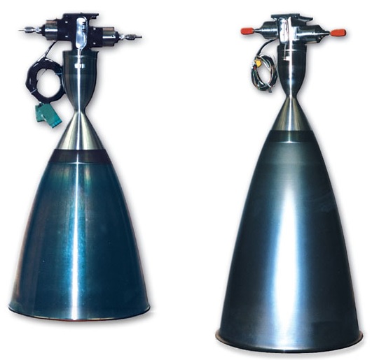
The two Liquid Apogee Motors installed on the satellite are standard bi-propellant engines delivering a thrust of 400 Newtons each, allowing the satellite to enter Geostationary Drift Orbit after three maneuvers performed at apogee. The S400 series built by EADS Astrium are bi-propellant engines using Monomethylhydrazine and Mixed Oxides of Nitrogen as propellants.
Depending on the version used, S400 provides 420 to 425 Newtons of Thrust with a specific impulse of 318-321 seconds. The engine system is isolated by firing pyro valves once the station acquisition in Geostationary Orbit is complete, leaving only the 10 Newton thrusters active for the mission.
The MSG satellites are equipped with a propellant gauging system in each of the tanks that has been specifically designed for a spinning satellite to provide accurate measurements of propellant remaining in the tank. The Gauging Sensor Unit can provide measurements at an accuracy of +/-0.05% of total tank volume to allow the mission team to keep track of propellant expenditure over the course of the mission.
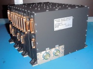
The Data Handling Subsystem of the MSG satellite contains three major components: the Central Data Management Unit CDMU, and two Remote Terminal Units, all interconnected via a standard OBDH data bus.
One of the RTUs is facilitated on the spacecraft’s Main Platform to monitor the equipment installed there while the second unit resides on the upper platform. The CDMU is in charge of commanding all satellite subsystems and includes a programmable Central Reconfiguration Module which can be used to reconfigure the Data Handling Subsystem in the event of specific alarms that are issued by the CDMU itself when off-nominal memory situations arise or in case the satellite enters safe mode.
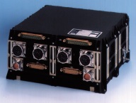
Mission Communications Package
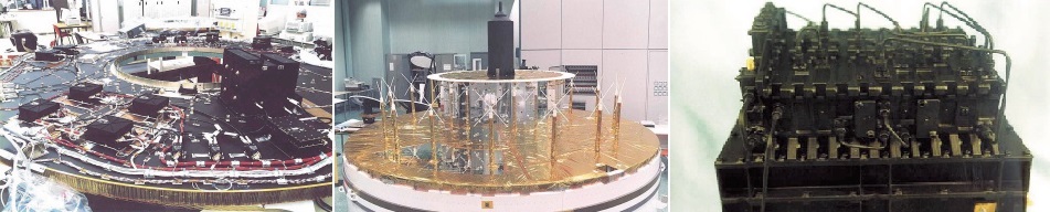
The Data Handling Subsystems is responsible for the reception and distribution of telecommands, the processing of commands handled directly within the DHSS, the acquisition of telemetry data and transmission for downlink, the acquisition of payload data, its onboard storage and transmission for downlink, the generation of On-Board Time solutions, the distribution of dedicated clocks, the read-out of raw data from payloads and commanding/monitoring of other subsystems via the RTUs.
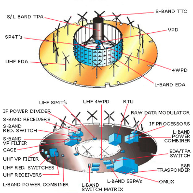
The Antenna Platform of the MSG satellite hosts a despun antenna subsystem fed from the transponder subsystems, capable of downlinking a number of signals. Raw data is downlinked to dedicated EUMETSAT ground stations at a frequency of 1,686 MHz and a data rate of 7.5Mbit/s while High Rate Information Transmissions and Low Rate Information Transmission is directly made to user terminals, the former at a frequency of 1,695MHz and a data rate of 2.3Mbits and the LRIT data at 1,691 MHz and 290kbit/s.
Furthermore, MSG support Data Collection Platforms operating in the 402MHz UHF Band to deliver data to the satellite at 100bit/s that is then stored and relayed at the 1,675MHz frequency. MSG also hosts a Search and Rescue Transponder receiving signals at 406MHz and relaying data to the ground at 1,544 MHz for rapid distribution to first responders.
Transmission of all types of data delivered by MSG can be made via the Electrically Despun Antenna operating in the L-Band range while the satellite also uses slotted waveguide Toroidal Pattern Antennas for the HRIT and LRIT data transmission and as backup for raw data. The UHF system supporting Data Collection Platforms and Search and Rescue uses a Crossed-Dipole Circular Array Antenna. Telecommand and telemetry data downlink is made via a printed quadrifilar Toroidal Pattern Antenna.
Meteosat Instruments
The Second Generation Meteosat spacecraft carry a suite of four payloads, two of which are instruments for operational meteorological & climate measurements, SEVIRI (Spinning Enhanced Visible and Infrared Imager) and GERB (Geostationary Earth Radiation Budget), and two supporting payloads, the Geostationary Search and Rescue System and the Data Collection System.
SEVIRI – Spinning Enhanced Visible and Infrared Imager
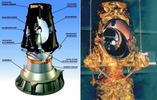
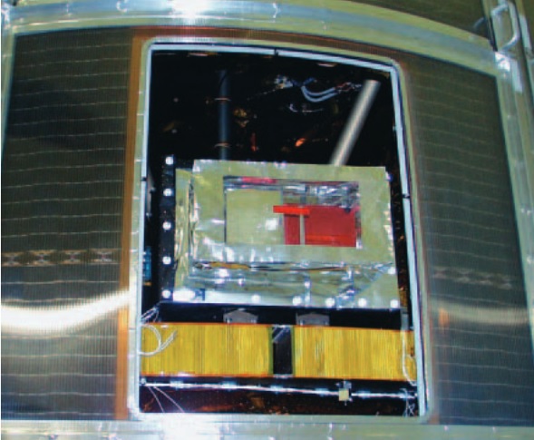
SEVIRI, the Spinning Enhanced Visible and Infrared Imager, is the principal instrument of the Meteosat Second Generation Satellite. It is a multi-channel imaging radiometer that supports imaging and sounding on 12 channels to deliver relevant meteorological data. The instrument was designed and built by EADS Astrium (now Airbus Defence and Space) and weighs 270 Kilograms, requiring 123 Watts of electrical power. It collects radiation across a field of view that is focused onto a detector by the telescope with the focal plane hosting a 12-channel detector that covers visible wavelengths as well as the infrared range of the spectrum. Overall, SEVIRI measures around one meter in diameter and stands 2.1 meters tall, filling up the central cylinder of the MSG satellite.
The SEVIRI Field of View is located perpendicular to the spacecraft spin axis meaning that the instrument FOV sweeps across the visible disk of Earth once per rotation.
The SEVIRI telescope aperture measures 50 by 80 centimeters and is equipped with a large baffle for the rejection of solar radiation from the sun angles that can be expected from the orbital layout of the mission that will see a variation of sun angles between +23.5 and -23.5 degrees from summer to winter.
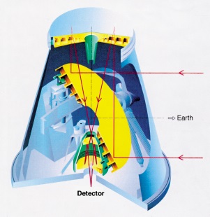
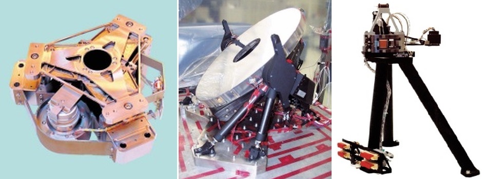
The Telescope and Scan Assembly TSA uses a three-mirror design that is often used in space-applications, featuring a primary concave aspheric mirror 51 centimeters in diameter installed centered on the satellite axis to collect the radiation and direct it to the secondary mirror. This mirror is also concave and aspherical with a diameter of 20 centimeters delivering the light to the convex-aspherical tertiary mirror that is 6 centimeters in diameter and focuses the light onto the detector assembly. Using this three-mirror design, SEVIRI reaches a focal length of 5.367 meters. The TSA has a length of 1.3 meters and employs a highly stable thermal design. Zerodur has been chosen as material for all mirrors due to its favorable thermal characteristics with a low expansion when temperatures are varying.
A rotating scan mirror is employed by SEVIRI to select the sector that is to be scanned, permitting continuous bi-directional image scanning. It is driven by a linear spindle drive and stepping motor. The scanning mirror is capable of selecting a scan of 22 degrees in the North-South direction and 18° in the East-West direction, capable of viewing the entire planet. Three lines per satellite rotation can be acquired (9 for the High Resolution Channels) meaning that one complete Earth image is created every 15 minutes. A nominal raw image consists of 3750 lines with 3834 pixels each with the exception of the High-Resolution Channels that include 5751 pixel in a single line.
Performance of the SEVIRI instrument is constantly checked to monitor the focus of the optics of the instrument that can be adjusted by moving the secondary and tertiary mirror assembly along the North-South Axis of the instrument to correct any issues in the focus of the instrument that may be the result of changing thermal properties. The translation of the M2/M3 mirrors is provided by a stepper motor, transmission gearbox and a roller screw that can be moved with high precision to resolve even minute optical alignment errors.
Another source for onboard calibration is the Calibration Unit – a Blackbody Calibration Reference Source that can be physically moved into the optical path at the focal point of the primary mirror to deliver a repeatable pattern of IR radiation within the instrument to check the performance of the infrared detectors. Cold space calibration will also be used to check for detector drift.
Refocusing System, Scan Assembly & Calibration Unit
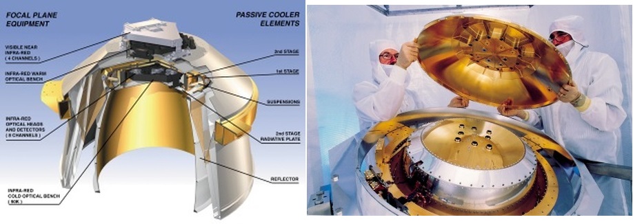
Because SEVIRI aims to detect a wide band of infrared wavelengths, its focal plane assembly has to be actively cooled to limit dark currents within the IR detectors. The Focal Plane Cooler Assembly is a passive two-stage cooler that consists of an external radiator and a sunshield covering the radiator. The thermally conductive focal plane assembly is connected to the radiator by a highly conductive bridge to maintain the focal plane at a temperature of 85 to 95 Kelvin depending on solstice conditions.
Focal Plane and Passive Cooler Design & Radiator Assembly
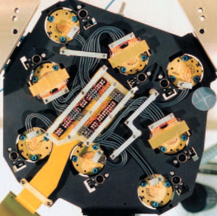
The Focal Plane Assembly of SEVIRI hosts a total of 42 detector elements dedicated to 12 channels covering wavelengths from 400 nanometers to 14.4 micrometers. All channels are co-registered and acquired simultaneously. Each of the 12 channels has three detector elements with the exception of the High Resolution Visible Channel that uses nine detector elements. The detectors for the visible channels are Photo-Voltaic Silicon Diodes, the Near-Infrared Channels use Indium-Gallium-Arsenide photovoltaic diodes and the eight infrared channels use Mercury-Cadmium-Telluride pixels.
The SEVIRI instrument features two two visible/NIR channels at 560-710 and 740-880 nanometers. A High-Resolution Visible Channel covers the entire visible spectrum into the near-infrared wavelengths from 400 to 1,100 nanometers, operating at a higher resolution. There are nine pure infrared channels that are covered by the instrument from wavelengths of 1.5 micrometers to 14.4 micrometers to be able to cover the relevant spectral bands for atmospheric readings.
The instantaneous field of view covered by the instrument is 4.8 Kilometers for the eleven ViS/NIR/IR channels and 1.67 Kilometers for the High Resolution Visible Channel as imagery is created by 3,750 by 3,750 pixels for the eleven standard channels at 3km spatial sampling and 5,625 by 11,250 pixels on the HRV channel at one-Kilometer sampling.
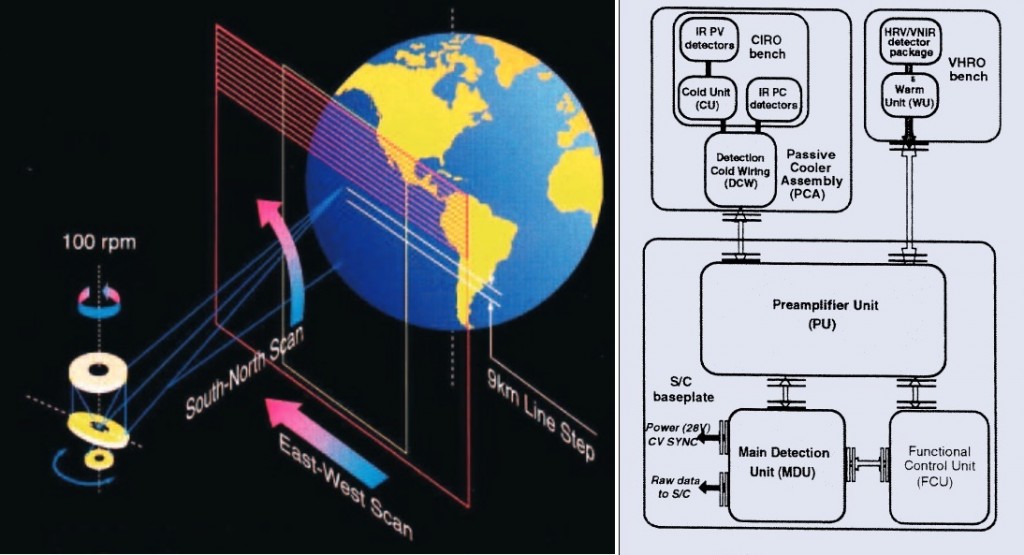
The generation of images uses a combination of the 100RPM spacecraft rotation and the motion of the scan mirror. The images are usually taken from East to West given the spin of the spacecraft with the S/C spin axis oriented parallel to the North-South direction. The scan in the North-South direction is achieved by moving the scanning mirror creating a composite of 1250 East-West scan lines creating 3750 image lines (11250 for HRV) that are combined to obtain a full picture every 12.5 minutes after which 2.5 minutes of data processing and calibration follow before the next image starts.
Raw data generated by the instrument comes at a rate of 75Mbit/s – 11.25Mbit/s from the three VNIR channels, 30Mbit/s for the eight IR channels and 33.75Mbit/s for the High-Resolution Visible channel. Onboard data processing is employed to generate an average instrument data rate of 3.26Mbit/s.
Scanning Mode & Signal Detection Chain
GERB – Geostationary Earth Radiation Budget
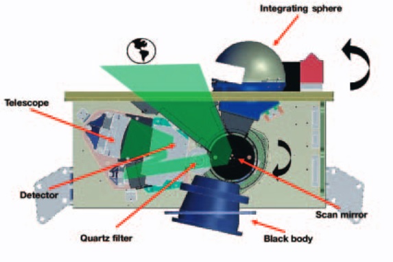
GERB, the Geostationary Earth Radiation Budget, payload was developed and manufactured by a consortium of industrial and institutional partners led by the United Kingdom with participation of Belgium and Italy. The instrument is an absolute radiometer capable of making high-accuracy measurements natural radiowave emissions from Earth, measuring the radiation budget of the planet as a function of energy input, reflection, emission and absorption. This data is of importance to the assessment of global climate change, food production, and natural disaster prediction. GERB is expected to make continuous measurements with particular focus on the reflected shortwave and the emitted longwave of the spectrum which provide essential pieces for the understanding of the Earth’s energy balance.
The instrument consists of two major components, the Instrument Optical Unit IOU hosting the telescope and focal plane assembly, and the Instrument Electronics Unit IEU.
GERB features a three-mirror anastigmatic telescope design fed by a rotating scanning mirror and including an additional folding mirror in the optical path towards the focal plane. This design offers a larger field of view than the conventional Cassegrain or Ritchey-Chrétien systems. Radiation entering the instrument is focused onto the Focal Plane Assembly that consists of 256 thermoelectric elements capable of measuring infrared radiation by absorbing energy delivered by the infrared radiation.
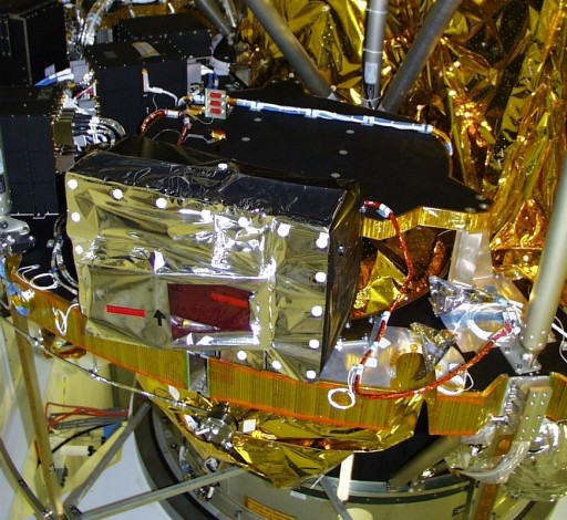
The GERB instrument is 45 by 20 by 20 centimeters in size, containing the imaging optics, the detector system, de-spin mirror and driver, quartz filter assembly, onboard calibration course and the focal plane assembly with its associated electronics. The total instrument mass is 25 Kilograms and the average power draw is around 35 Watts.
The de-spin mechanism of the GERB instrument rotates the de-spin mirror at 50 RPM into the opposite direction of the spacecraft spin to temporarily freeze the image to be able to complete 40-millisecond exposures of a still Earth despite the 100 RPM spin of the spacecraft.
Like the main instrument of the MSG satellite, GERB assembled a global image over the course of a 12-minute scanning sequence by obtaining individual columns that are combined to the final data products.
The GERB detector is a 256-element blackened linear thermoelectric array installed in the North-South direction to comply with the imaging technique. The detector assembly is divided in two sections, one is covered by a quartz filter element, the other receives unfiltered radiation. The filter blocks any wavelengths over 4 micrometers, allowing the Short-Wave Channel to only observe radiation from 320 nanometers to 4 micrometers while the Total Band detects infrared radiation up to a wavelength of 100 micrometers. The Longwave Band (4-100 micrometers) is isolated through simple subtraction of the Shortwave readings from the Total channel.
Overall, the instrument has a field of view of 44.6 by 39.3 Kilometers at nadir and acquires data at a spatial resolution of 3 Kilometers with an absolute radiometric accuracy of 1% in the shortwave range and 0.5% in the Total band.
The detector assembly relies heavily on Application Specific Integrated Circuit technology with four ASICs connected to the focal plane, each receiving 64 inputs of data from the individual pixels. This design was favored over a Field Programmable Gate Array due to the signal-to-noise and timing requirements that needed the electronics to be in close proximity to the detector plus the low signal strength delivered by the detector. The ASICS deliver the signals to the analog processing system for amplification before signal conditioning and processing into digital data frames that are delivered from the IOU to the spacecraft at a data rate of 50.6kbit/s.
Calibration of the GERB instrument is accomplished through viewing of deep space for a zero reference, the solar input viewed through a solar transmission diffuser, and viewing of an internal blackbody. The signals difference between the blackbody and Earth-view is calculated on every rotation of the spacecraft.
Search and Rescue Payload
The Meteosat Second Generation Satellites support the Geostationary Search and Rescue system S&RSAT/COSPAS by receiving beacon signals and distress calls on the 406MHz UHF uplink frequency from a variety of transmitters used on ships, aircraft and other vehicles and by individuals. Signals that are received through this system are then downlinked with short latency to an appropriate ground station to alert first responders.
Data Collection System
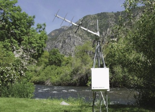
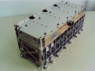
MSG carries a communications system compatible with the Data Collection System to receive data from remote terminals (Data Collection Platforms) and relay them to ground stations for processing. DCPs can be deployed virtually at any location on the globe to provide in-situ measurements of meteorological data that is then uplinked to satellites and transmitted to ground stations for collection, processing and distribution. The DCPs operate in the UHF band at 401/402 MHz.
These platforms include remote weather stations, buoys at sea to measure sea state and alert in the event of tsunamis as well as other measurement stations that are deployed in remote locations. Data received via the DCS UHF antenna at data rates of 100 to 300bit/s is relayed to the ground via the spacecraft comm system for processing and distribution. MSG can support up to 210 channels on the regional frequency plus 40 international channels.
Photo: Example of a Data Collection Platform
Ground Segment
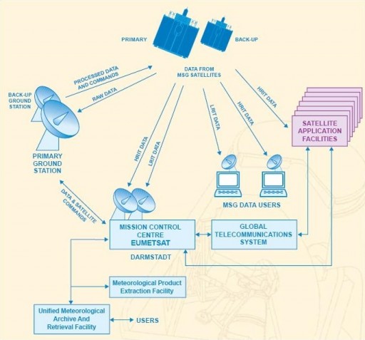
The MSG Ground Segment is centered around the Mission Control Center at the European Space Operations Center in Darmstadt from where the spacecraft is operated. MSG’s primary ground station is located in Usingen, Germany while a Backup and Ranging Station is located in Maspalomas, in the Canary Islands. The primary purpose of the Mission Control Center is the operation of the spacecraft, namely the scheduling and monitoring of spacecraft science and maintenance activities.
To ease the process of data handling and distribution, a specific application ground segment was set up for MSG composed of a Meteorological Product Extraction Facility and Unified Meteorological Archive and Retrieval Facility, both at EUMETSAT in Darmstadt. These facilities receive all data from the spacecraft, complete initial processing and science product generation and then distribute data to users, also archiving all data for future use in a variety of applications. Data products are delivered in real time to a number of Satellite Application Facilities that are in charge of producing specialized data products using EUMETSAT Data including the SAF on Ocean and Sea Ice, SAF for Nowcasting and VSRF, the SAF on Numerical Weather Prediction, SAF on Land Surface Analysis and the SAF on Climate Monitoring. All SAFs deliver their science or operational data products to their specific user groups.
