
MAHLI Instrument Information
MAHLI is a full color camera that is located on the turret at the end of MSL’s robotic arm. This camera produces close-up pictures of soil/rock targets with a resolution of up to 1600×1200 pixels. The camera is focusable from working distances of 20.4mm to infinity. Its resolution at a distance of 25mm is 15µm per pixel.
Color images are achieved by using a Bayer Pattern Filter which can be found in many common digital cameras. Color quality of MAHLI Images are comparable to that of standard digital cameras. Nighttime image capabilities are provided by two sets of two white light LEDs. Each pair is individually activated to provide redundancy to the illumination system. Two Ultraviolet LEDs (365nm) are being used to search for fluorescent materials during night-imaging sessions. Those UV LEDs are not calibrated tools and are used on a ‘best-efforts’ basis. UV research requires nighttime operation of MAHLI which is limited due to thermal and power constraints. It is expected that MAHLI will be used for occasional night time operations when battery charges are providing enough margin for night-time rover operations.
The MAHLI optics can be focused and Autofocus capabilities provide in-focus images regardless of positioning of the camera head by the robotic arm. Onboard Focus Stacking is also provided by the instrument as close-focus views of targets might not be in-focus over the entire image depending on working distance and surface conditions. In those cases, MAHLI takes images at up to 8 focus positions that include in-focus portions of all areas of the target. Onboard software then processes these images and merges them into a single best-focus image. Focus stacking, or z-stacking, provides information of a target’s microtopography by generating a range map of the target, and an additional advantage of this technique is the reduced downlink capability that is provided with onboard processing.
Camera placement is controlled by the robotic arm that moves the optics into a position from where MAHLI can image the targets. Contact of the optics with any materials is being prevented by two pokers which work as contact sensors.
This way, there is no contamination of the optical elements. Positioning of the camera is done in ways that produce images of increasing spatial resolution, stereo images and mosaics. Data storage is provided internally. 8 Gigabytes of storage volume are available. In addition to that, 128MB of SDRAM Buffer are integrated in the MAHLI system. Thumbnail images are created automatically and can be easily downlinked to Earth. This enables scientists to only downlink chosen images in full resolution once assessing the thumbnails. Image compression will be performed just before downlink. In addition, MAHLI can produce sub-frame images, only sending the parts of an image that are of interest to scientists to further reduce downlink volume. The large storage capability makes it possible to store images uncompressed and make them available for two or more downlinks should that become necessary due to compression issues. In addition to still photography, MAHLI can produce high definition (720p) video with 7 frames per second.
Instrument Description
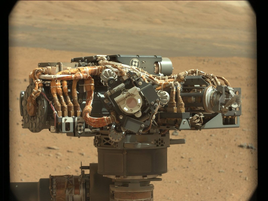
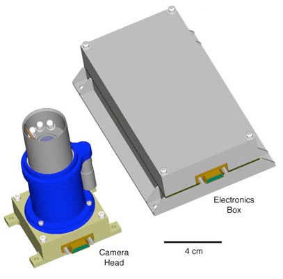
MALHI is comprised of three major parts: The camera head, a Digital Electronics Assembly (DEA) and a calibration target. DEA is housed inside the Rover’s Warm Electronics Box to maintain thermal requirements. The camera head is mounted on the turret at the end of the robotic arm. On the turret, numerous other instruments are mounted and can be individually controlled and moved into their correct positions. The calibration target is installed on the robotic arm azimuth housing. DEA and camera head are connected by a data cable that was provided by NASA’s Jet Propulsion Laboratory.
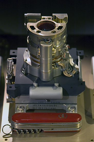
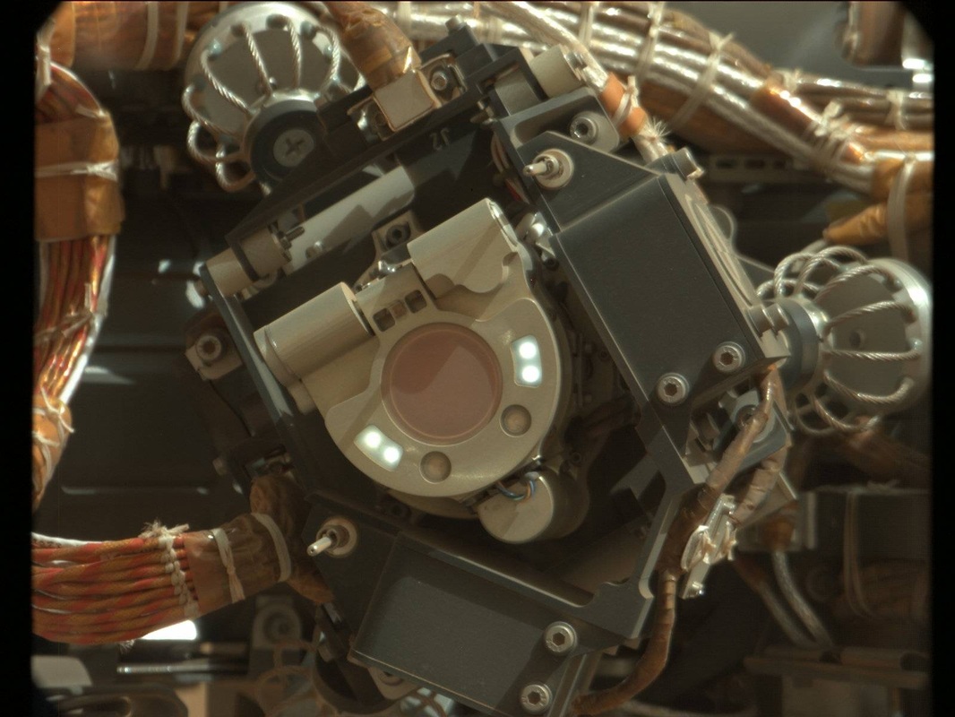
Camera Head
The main component of the MAHLI Instrument consists of three functional parts: a focal plane assembly, an optomechanical assembly and the electronics assembly. The Camera head shows similarities to the MastCam and MARDI Camera Heads.
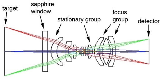
The optomechanical assembly is comprised of integrated optics, focus elements and dust cover mechanisms. A single motor is included to adjust focus and dust cover configurations. The focal length of the optics ranges from 18.3mm for the closest working distance and 21.3mm for focusing infinity. The field of view varies from 34° to 39.4°. The optics are protected by a sapphire window at the front of the instrument.
There are six fixed optical elements and a group of three movable elements. A surface coating on the sapphire window prevents near-infrared wavelengths from entering the instrument. MAHLI images have a spectral range of 380-680nm. All optical elements are sealed within the assembly to avoid dust contamination. An Aeroflex Stepper Motor drives multiple parts of the instrument being equipped with a 256:1 gearhead.
This motor controls the commandable opening and closing of the dust cover. MAHLI can operate at temperatures greater than -70°C, but the minimum preferred temperature is 50°C – heaters may be used to raise the instrument’s temperature above that point for night-time or early morning operations. When the instrument is not activated, the cover is in its closed position to protect the LEDs and the front optical element from dust contamination. The cover is a transparent Lexan® cover. Should the opening mechanism fail, images could still be acquired and the LEDs can still work through the cover. Camera outputs are being amplified and digitized in the Focal Plane Assembly that includes the CCD and various electronics. The optics send the image to a Kodak interline transfer CCD. The array has 1600×1200 active pixels with square pixels of 7.4 micrometers. The electronics include the CCD drivers, the motor driver electronics and electronics that interface with the DEA to accept commands and send data. Outputs of the camera are sent at rates of up to 120Mbps over a six-pair parallel interface.
MAHLI Optical Assembly
DEA
The MAHLI DEA is responsible for data processing, commanded image compression and buffering. It includes power conversion elements that provide electricity for all subsystems of the instrument. DEA receives images made up of 12-bit pixel values from the camera head and converts them automatically to 8-bit imagery. Pixel processing, Bayer Filter interpolation and image compression are performed in the FPGA (Field Programmable Gate Array), while focus stacking to achieve best-focus images is done in software only.
Contact Sensors
Two Pokers are mounted around the outside of the MAHLI camera head. When a sensor makes contact with a surface, the robotic arm is commanded to stop its motion immediately to prevent any contamination from occurring at the front of the instrument. Both sensors were designed and built at NASA’s Jet Propulsion Laboratory.
Calibration
Prior to being delivered for vehicle integration, MAHLI underwent an extensive calibration effort in 2008. After being mounted on the MSL Rover, additional tests and calibrations were performed in late 2010. Those were done to determine the robotic arm’s positioning capabilities and to identify any noise sources on the rover. Also, contact sensor performance was verified. On Earth, properties such as absolute/relative radiometry, light transfer and noise, geometry, resolution, system spectral throughput, and precision of the z-stacking application were characterized to understand images taken on Mars.
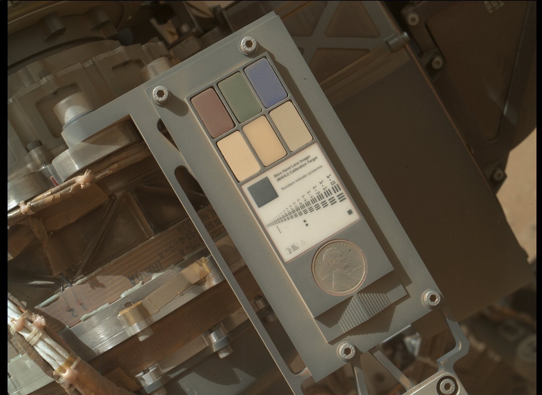
After landing on Mars and in the operational phase, MAHLI is being calibrated regularly by using the Calibration Target that is mounted on the Rover. This target will verify color/white balance, image resolution and focus, as well as performance of the LED and UV LEDs.
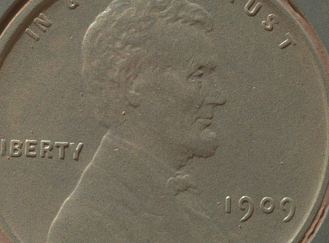
The Calibration Target is comprised of four components, six small plates of different colors that are used for color characterization of MAHLI, a metric bar graphic for focus characterization, a stair-step pattern for depth calibration, and a penny coin that can also be used for focus characterization. This 1909 VDB Lincoln penny was donated by MAHLI Principal Investigator Ken Edgett during MSL Construction. Dust accumulation on the target is prevented by vertical installation of the actual target point.
Calibration Target & Penny
Operation
Exposure times vary to accommodate the different image types and environmental requirements. Typical daylight images will be acquired with an exposure of 5 to 15 milliseconds. Shadow images and images with the use of the White LEDs will require an exposure of approximately 80 milliseconds. Imagery of UV illuminated targets are taken with an exposure of 2 seconds.
Three different image types can be acquired by the MAHLI Instrument: Raw Images without RGB Interpolation and Compression, lossless predictive compression (also without RGB Interpolation and a compression of 1.7:1) and JPEG Photography with interpolated color. Compression of JPEGs can be configured as required (lossless to very lossy). JPEGs require a small data volume and are mostly be taken with the instrument to make downlink easier. Thumbnail images are small (150×200 pixel) JPEG images that are being downlinked to Earth to determine which high resolution images to downlink and at which compression rate the particular image is required for further analysis.
Mission Operations
MAHLI operations are based at Malin Space Science Systems, San Diego, California where professionals that have several years of experience in the field of Rover operations will operate the instrument from. They will be commanding the instrument based on inputs from the science team to obtain images required to meet mission objectives. They are also in charge of logging engineering and science data that they receive.
MAHLI Operations
- Closeup imagery of rocks and fine regolith targets from a near-normal viewing position along the z-axis of the camera
- Context Photography of targets
- Imaging oblique views of targets
- Night Imaging
- UV Imagery to identify fluorescent materials
- Observing seasonal frost and monitoring changes in frost profiles over night
- Acquiring mosaic and stereo images
- Imaging of terrain and dust-raising events when in a stowed position
- Sky imaging to determine sun position
- Drill Hole Imaging
- Sample Observation Tray imaging
- Periscope Imaging when the robotic arm is extended upright to place MAHLI high above the ground
- Acquisition of Scientific Video (Grain Motion Profiles)
- Acquisition of public outreach imagery (still and video)
- Rover problem diagnosis (looking at the underside&wheels and examining the CheMin and SAM sample inlets)
- Rover Problem Diagnosis (View under the rover, at the wheels from the side, look inside sample inlets)
- Rover self Portraits for educational purposes
Science Goals,
Source: Malin Space Science Systems (msss.com)
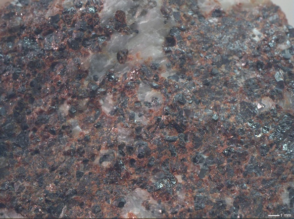
Examine rocks at the MSL site. MAHLI data will be used to examine and contribute to studies of the texture, morphology, structure, mineralogy, stratigraphy, history, and alteration of rocks encountered by MSL.
Examine fines at the MSL site. MAHLI data will be used to examine martian fines—those materials in the regolith that are smaller than 4 millimeters in diameter, such as sand, silt, and dust. MAHLI will contribute to the understanding the processes that acted on the fines and upon individual grains by studying their physical and mechanical properties, the results of rover hardware interaction with fines, and the stratigraphy, mineralogy, and depositional processes involved.
Examine frost and ice at the MSL site. Frost was seen at middle latitudes by the Viking 2 lander. It was also seen at equatorial latitudes by the Opportunity rover. MAHLI can acquire images at night, when frost is most likely to occur. If present, MAHLI will be used to examine frost texture, morphology, thickness, stratigraphic position (if in the subsurface), relation to regolith, and, if possible, observe changes over time.
Facilitate other MSL science. MAHLI will be employed to help the other MSL instrument teams identify and document materials that will be examined by their instruments, including samples that will be collected by the rover for detailed study in MSL’s Analytical Laboratory experiments.
