Lunar Laser Communication Demonstration
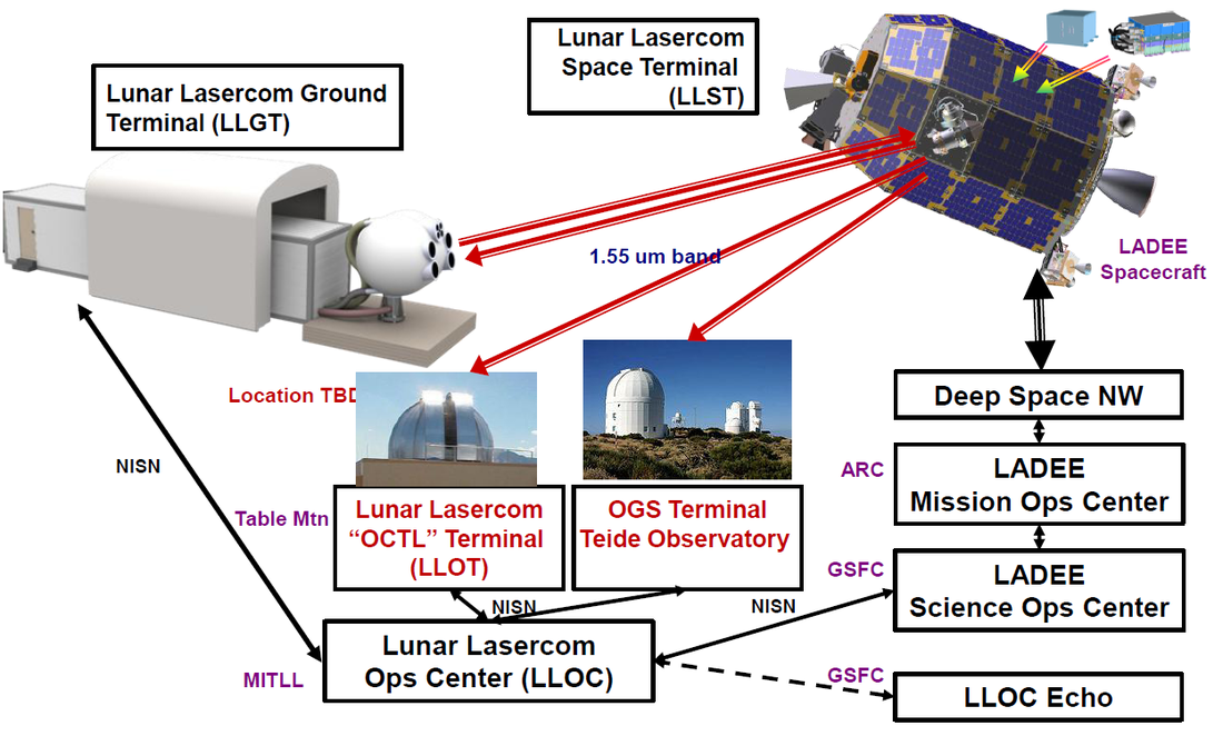
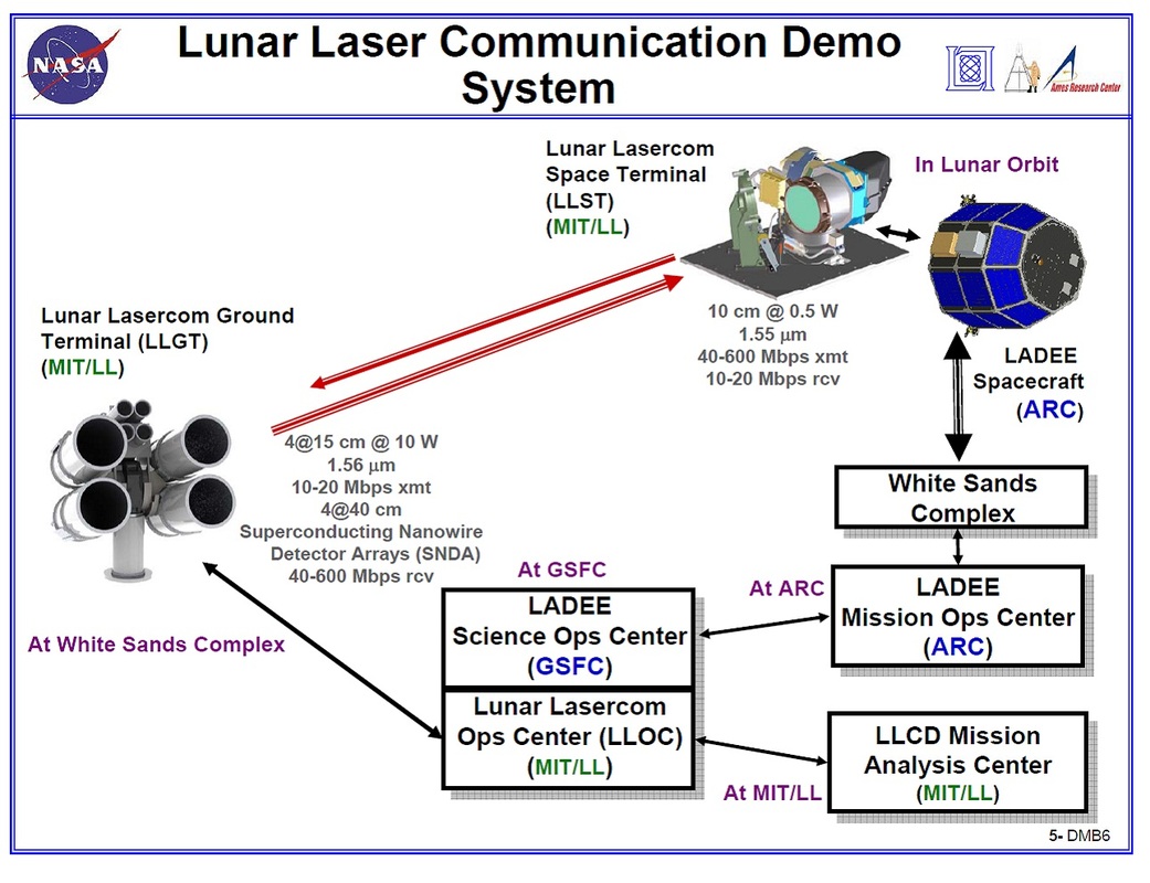
Part of LADEE’s payload is a technical demonstration that will be used to demonstrate high data rate optical communications between Earth and the Moon in preparation for use of Laser Communication for space and deep space applications. The LLCD System consists of three primary parts: The Lunar Lasercom Space Terminal mounted on LADEE and the Lasercom Ground Terminal with Lasercom Operations Center on Earth. Because the LLCD system is part of the payload, it is not considered part of LADEE’s communications system as all data that is required for mission success is up- and downlinked via LADEE’s S-Band system. LLCD will only demonstrate data transfers.
The project is being managed by the Massachusetts Institute of Technology MIT and Lincoln Laboratory LI in cooperation with NASA’s Goddard Spaceflight Center. The goal is to demonstrate duplex optical communications from a spacecraft in lunar orbit to an Earth-based receiver. LLCD achieves data rates of up to 620 Mbit/s for uplink and 20 Mbit/s for downlink.
Additionally, the payload will demonstrate laser ranging with a 2-way time of flight error of less than 200 picoseconds providing sub-centimeter accuracy.
Lunar Lasercom Space Terminal
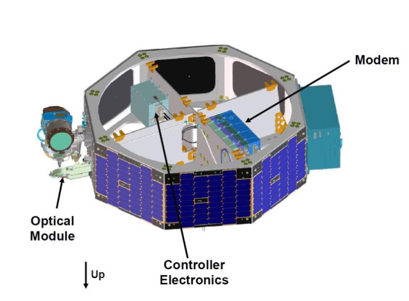
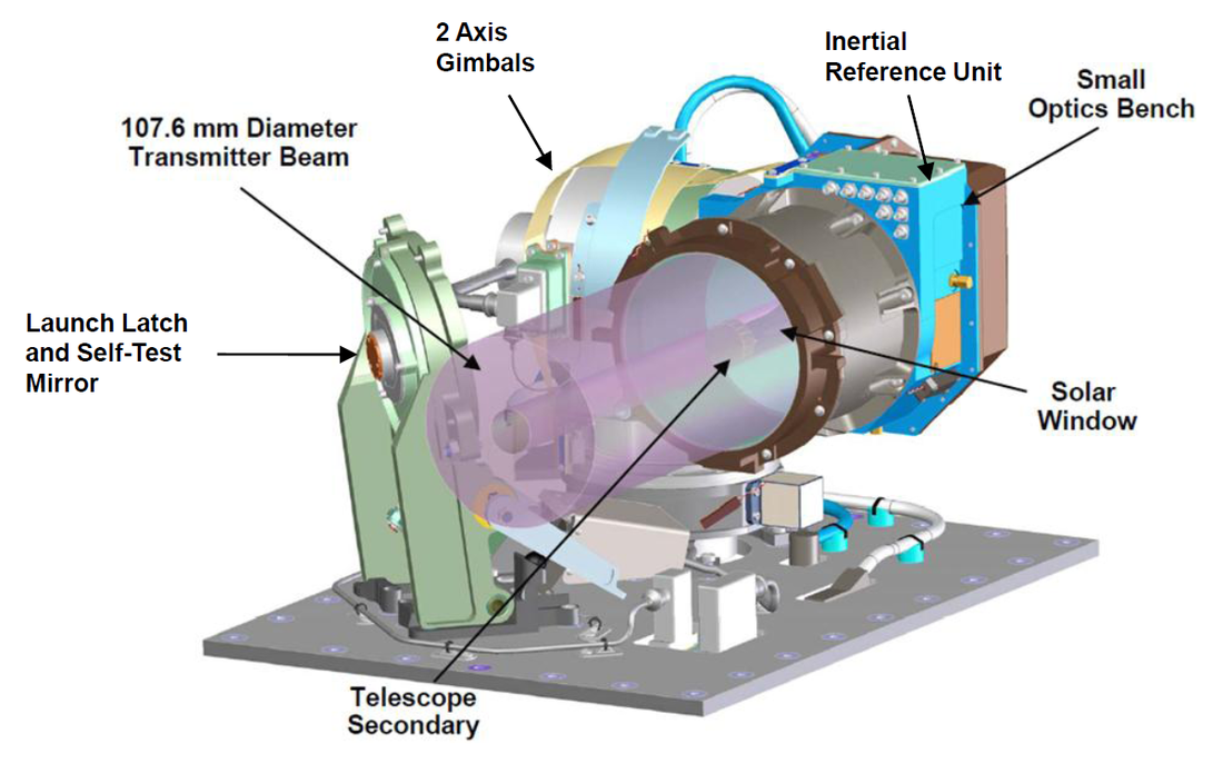
The Lunar Lasercom Space Terminal is mounted on the LADEE spacecraft’s payload module and consists of an optical module, a modem module, and an electronics module. The system demands about 137 Watts of power during operation and weighs about 32 Kilograms. The optical payload is mounted on the exterior of the LADEE vehicle while the modem and electronics reside on the inside.
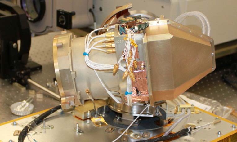
The optical module is a 10-centimeter cassegrain telescope (using a primary concave mirror and a secondary convex mirror aligned about the optical axis to focus light on the detector). The telescope is mounted on a two-axis gimbal assembly that allows LLCD to operate from a variety of spacecraft orientations. The assembly is inertially stabilized using a Magnetohydrodynamic Inertial Reference Unit that rejects any high-frequency motion to keep the optics perfectly stabilized.
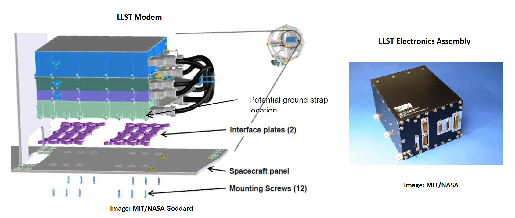
A wide field of view Indium-Gallium-Arsenide Detector provides spatial acquisition and coarse tracking of the optical uplink signal. Optical fibers connect the telescope to the modem module that contains the optical transmitter and receiver. The fibers are installed on piezoelectric actuators that are used for fine spatial tracking of the uplink signal. The LLST modem is comprised of four stacked elements – the power, digital, analog and electro-optical slices that were built and tested individually before being integrated into a single unit. The system supports downlink data rates of 39 to 620 Mbit/s which allows optical link demonstrations in a variety of atmospheric conditions.
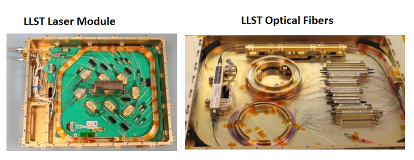
The modem module uses digital electronics that aggregate the different downlink data sources which include science data, telemetry and loopback of data uplinked via LLCD. A high-efficiency half-rate code is used to encode data which are then modulated onto an optical carrier using pulse-position format. The modulation downlink occurs in the electro-optical slice that utilizes a Master Oscillator Power Amplifier architecture.
A continuous wave laser at 1550 nanometers is coupled with a Lithium niobate optical modulator and accomplishes the electrical to optical data conversion. The amplification of the optical data to 0.5W is achieved by a two-stage Erbium-Doped Fiber Amplifier. Each stage is pumped with two grating stabilized 976nm pump lasers.
The uplink receiver uses am optically preamplified direct-detection EDFA with low-noise. A pulse-position demodulator is used to demodulate the received uplink waveform before decoding of the signals in a high-density S-RAM based field programmable gate array.
The electronics assembly is based on a single-board computer that provides closed loop control of the entire LLCD payload. It provides command and telemetry interfaces to the other LLCD components and to the LADEE central avionics unit being connected to the mass memory board of the spacecraft via a high-speed data link – the only such link used board the LADEE vehicle outside of LLCD.
Lunar Lasercom Ground Terminal
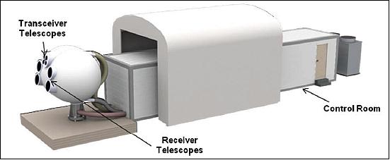
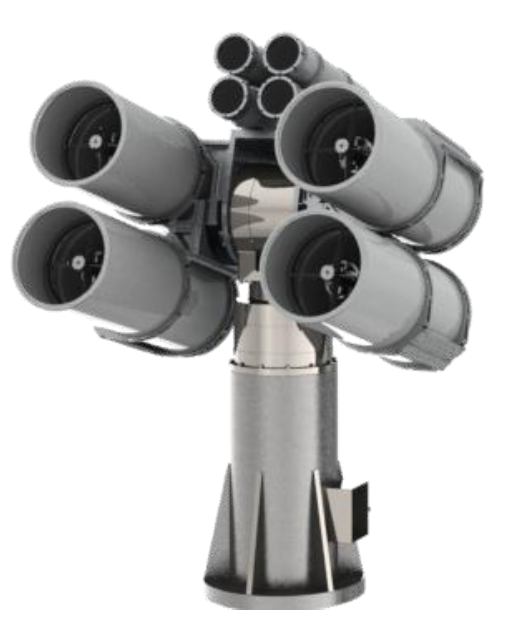
The Lunar Lasercom Ground Terminal features an array of telescope-based transceivers and receivers. Four 15-centimeter refractive telescopes are used for uplink while four 40-centimeter reflective telescopes are used for the optical downlink. The telescopes are connected via optical fibers to the respective transmitters and receivers located in a control room.
All telescopes are installed on a single elevation over an azimuth gimbal providing coarse pointing for all eight telescope units to achieve near hemispherical coverage.
Each telescope is equipped with a fast-steering mirror for high-bandwidth tracking of the optical downlink and to correct any pointing biases between the telescopes on the gimbal. Fiberglass enclosures protect the telescopes and maintain suitable operating conditions.
The Control Room that is set up next to the telescope houses all modem and electronics assemblies required to operate the system. Four Erbium-Doped Fiber Amplifier-based optical transmitters provide the pulse-position modulated signals of about 10W for uplink. The wavelengths of each transmitter are detuned to allow for non-coherent combining of the signals at the space terminal.
The downlink receiver uses photon-counting superconducting nanowire arrays that are operated at cryogenic temperatures for high photon detection efficiencies exceeding 1 bit per detected photon.
To operate the system in the presence of atmospheric turbulences while preserving the polarization of the downlink signal, a polarization-maintaining fiber is used to couple the receiver telescopes to the detectors. Signal demodulation and decoding is accomplished with digital electronics assemblies located in the control room that also generate the waveforms for the optical uplink and pull data from various sources.
The ground terminal is set up at the White Sands Complex. The European Space Agency has modified its Optical Ground Station on Tenerife, Spain to participate in the LLCD project.
LLCD Operations
Due to its high power demand, the Lasercom Terminal on LADEE will only be used during spacecraft commissioning after arriving in lunar orbit. LLCD is expected to accumulate about 16 hours of operations being used for a max of 15 minutes per orbital pass due to power limitations. Also, the system can only be used when the White Sands Ground Station or the ESA station is in view, reducing the amount of lasercom sessions to about 5 per day.