HTV Spacecraft Information
The H-II Transfer Vehicle is Japan’s International Space Station Resupply Spacecraft that is used to deliver cargo to the Station. It was designed by the Japan Aerospace Exploration Agency. HTV is built and operated by JAXA and Mitsubishi Heavy Industries. The HTV offers the capability to carry logistics materials in both its internal pressurized carrier as well as in an unpressurized carrier for exterior placement. The vehicle is launched aboard the H-IIB Rocket, Japan’s Heavy Lift Launcher. A full H-IIB Overview can be found here.
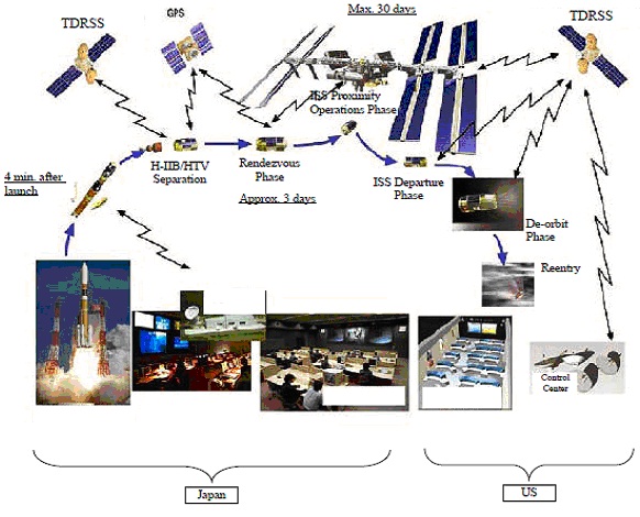
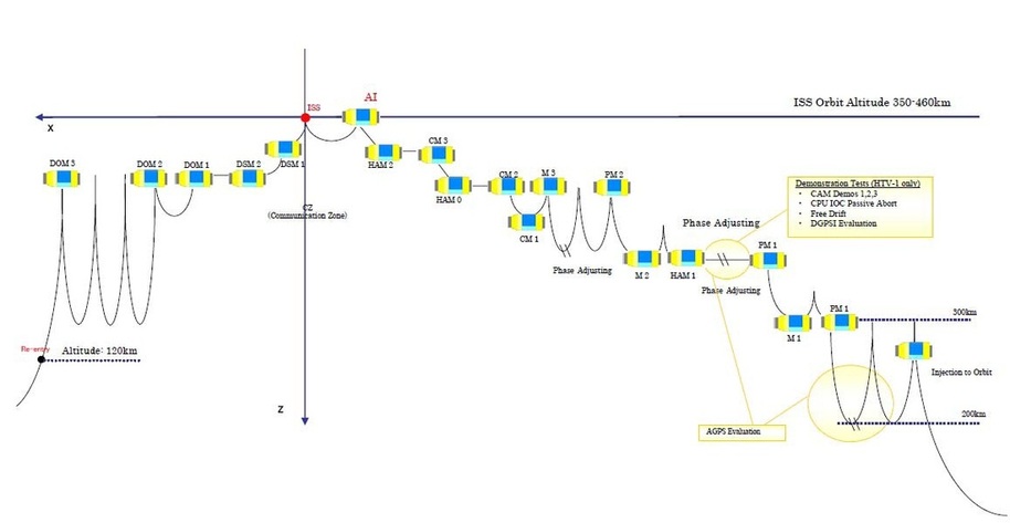
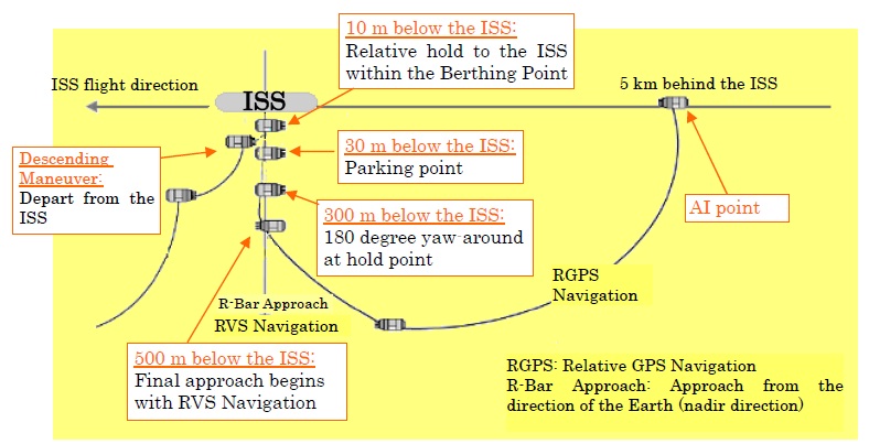
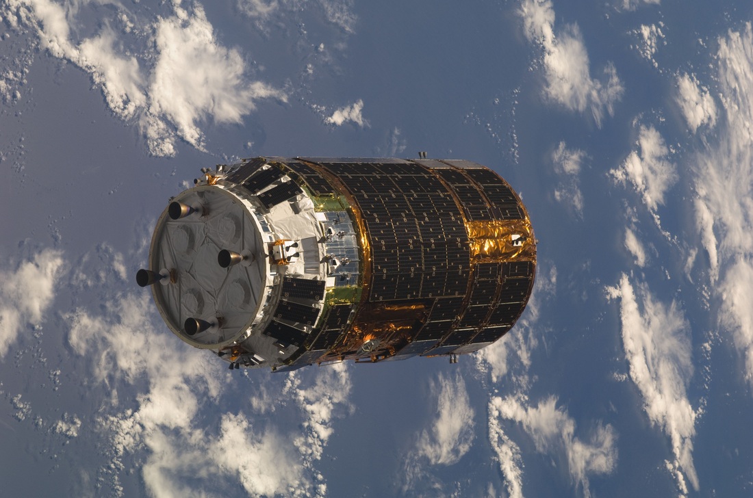
After launch, HTV links up with the International Space Station and begins its Rendezvous Sequence at a Distance of 5 Kilometers making a series of complex maneuvers to reach a point 10 meters below the Space Station. The Space Station’s Robotic Arm then grapples the vehicle and berths it to the Harmony Module. After hatch opening, the delivered cargo items can be transferred to the Station and the external payloads can be removed with the Robotic Arm. Before unberthing, the vehicle is loaded with trash and no-longer-needed items for disposal. After being released by the SSRMS, the Spacecraft retreats to a safe distance to ISS and makes its deorbit burn followed by destructive re-entry to end the mission. HTV is capable of staying at the Space Station for about one month and perform solo flights of up to 100 hours.
Vehicle Description
| Length | 10m |
| Diameter | 4.4m |
| Spacecraft Weight | 10,500kg |
| Launch Mass | 16,500kg |
| Payload Capacity | 6,000kg |
| Pressurized Payload | 5,200kg |
| Unpressurized Payload | 1,500kg |
| Return Payload | None |
| Pressurized Volume | 14m³ |
| Power Generation | 57 Solar Panels |
| Main Propulsion | 4 x 490N Thrusters |
| Attitude Control | 28 Thrusters |
| Fuel | Monomethylhydrazine |
| Oxidizer | Mixed Oxides of Nitrogen |
| Propellant Mass | 2,400 Kilograms |
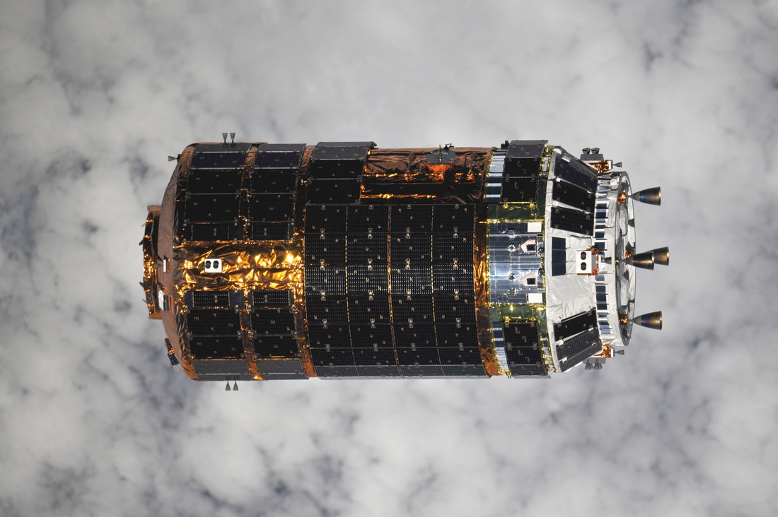
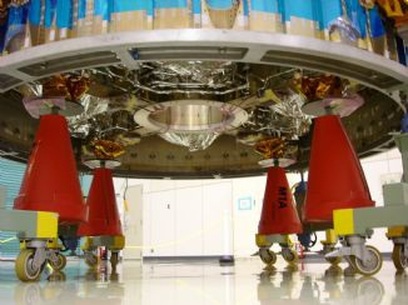
The HTV Spacecraft in its nominal configuration is 10 meters in length and has a mean diameter of 4.4 meters. It consists of four sections, the Pressurized Logistics Carrier PLC, the Unpressurized Logistics Carrier ULC, the Avionics Module AM and the Propulsion Module PM. HTV has a liftoff mass of 16,500 Kilograms carrying up to 5,200 Kilograms of payloads inside the Pressurized Logistics Carrier and 1,500 Kilograms of external payloads.
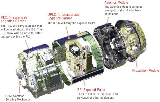
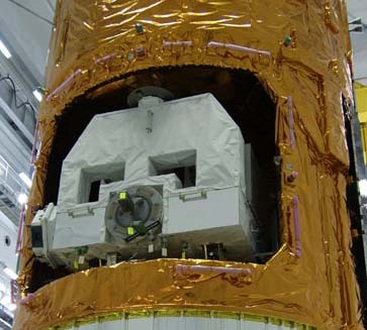
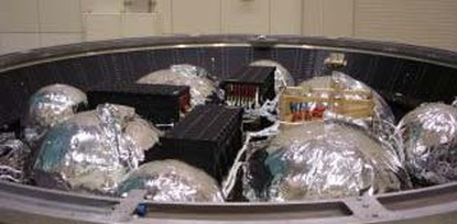
Pressurized Logistics Carrier
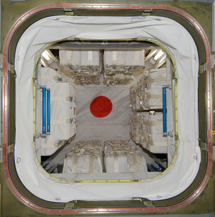
The Pressurized Logistics Carrier is 3.3 meters long and carries cargo for onboard use (experiment racks, food, and clothes). It has a pressurized volume of 14 cubic meters. The Module houses two rack bays. Bay 1 is located on the hatch side and accommodates the International Standard Payload Rack (ISPR) or a fixed type of HTV Resupply Racks (HRRs). ISPRs can be removed and transferred to ISS entirely.
Bay 2 in the rear of the PLC contains only a fixed type of HRRs. The Racks are filled with Cargo Transfer Bags that are removed and transferred to ISS. Bags with return cargo can be placed in the respective Racks for the return to Earth. The PLC features electrical, thermal environment control, navigation and crew support systems. The electrical system of the PLC receives 50V DV Power from the HTV Avionics Module that is then distributed to the equipment inside the compartment and its subsystems. When berthed with ISS, the PLC received 120V DC from the Space Station and routed the received power to the Avionics Module for conversion.
The PLC is outfitted with wall heaters to control the internal environment of the pressurized compartment. Prior to berthing, the temperatures inside the PLC will be equalized to the internal temperature of the ISS in order to prevent dew condensation which can cause serious problems in the Zero-G Environment. Pressure and Temperature sensors are installed inside the PLC to monitor the environment inside the spacecraft. HTV is equipped with a vent valve for pressure regulation.
While berthed to the Station, HTV air will be circulated by fans through the Inter-Module Ventilation system (IMV). Some detectors mounted inside the PLC are hooked up to the ISS Control System and will set off an alarm when a fire is detected. The ISS Control System immediately stop the IMV Fans and notify the crew members and control centers by sounding alarms throughout the station. Four interior lights are installed inside the PLC which can be manually turned on and off by the ISS Crew Members. Prior to unberthing of the HTV, the light fixtures are removed for use aboard the Space Station.
On the outside of the PLC, four attitude and two capture lights are mounted. There are two red lights on the port side, two green lights on the starboard side and a white and a yellow light on the end cone ring.
These lights are used by the ISS Crew to visually verify the orientation and position of the Spacecraft during orbital nights when Rendezvous and Approach are in progress. The flashing capture lights become visible to the ISS crew at distance of about one Kilometer while the attitude lights become visible at a range of 500 meters. At the top of the PLC is a Passive Common Berthing Mechanism with the HTV Hatch.
Unpressurized Logistics Carrier
The Unpressurized Logistics Carrier and its Exposed Pallet are 3.5 meters in length and houses up to 1,500 Kilograms of external Payloads. The ULC/EP is used to carry external experiments and/or orbital replacement units (ORUs) to the Space Station. Once berthed to ISS, the Exposed Pallet is removed from the ULC by the ISS Robotic Arm and is handed over to the robotic arm of the Kibo Module which then attaches it.
Mobile Base System (MBS) or Kibo’s Exposed Facility (EF) for unloading operations. After the Payloads are unloaded, the EP is re-installed in the ULC Section of the HTV Spacecraft. The EP is held in place aboard HTV’s ULC by four Tie-down Separation Mechanisms (TSMs) which secure the Pallet during launch and solo flight. The Hold-Down Mechanism receives, holds and pulls the EP in during EP removal and re-installation by the Station’s Robotic Arm. A Harness Separation System is used to separate power and data cables between the ULC and EP that are needed to power and control the Payloads aboard the Pallet. Three guide rails are located near the aperture of the ULC, one each on the port side, the starboard side, and the nadir side.
Wheels and Guide Rails are used during the removal and installation of the EP. The Exposed Pallet includes Cargo Attachment Mechanisms to hold the individual payloads in place and release them when commanded, Connector Separation Mechanisms to separate Payload Power and Data Connections when being removed, and a Flight Releasable Grapple Fixture (FRGF) and a Power and Video Grapple Fixture (PVGF).
Avionics Module
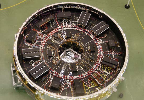
The 1.2-meter Avionics Module of the HTV Spacecraft includes guidance navigation & control, communications, data handling, and electrical power subsystems. These systems control all aspects of the vehicle’s flight. The Guidance System of HTV uses data coming from position/attitude sensors to provide navigation information and vehicle control. HTV uses GPS Systems as well as Rendezvous Sensors, an Earth Sensor to collect navigation data. A Navigation Control Computer and an Abort Control Unit are part of the vehicle’s avionics.
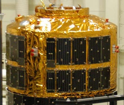
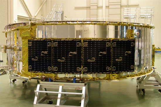
The Communication System of the vehicle uses the Tracking and Data Relay Satellite System for command uplink and telemetry downlink. An S-Band System is used for direct communications with ISS during Proximity Operations. The Electrical Power Subsystem consists of two Main Bus Units, eleven non-rechargeable Primary Batteries, a single Secondary Battery that can be recharged and a Power Control Unit. The Secondary Battery is primarily used during the flight for power supply during orbital night and is charged with power coming from the solar panels. The other batteries are used when the S-BAT is not sufficient for power supply. Power generated by the solar arrays is regulated by the Power Control Unit that distributes power to the Main Bus Units and the S-BAT. The MBU then distributes power to all vehicle systems. The PCU is also used to receive power from the Station to route it to the rest of the vehicle. A total of 57 power-generating solar panels are installed on the exterior of the HTV (PLC: 20 Panels, ULC: 23, AM: 8, PM:6).
Propulsion System
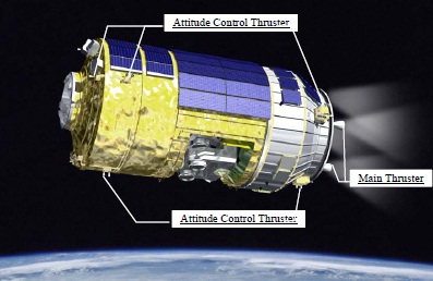
The Propulsion System of the HTV consists of the 2-meter Propulsion Module and Thruster installed on the other segments. The Propulsion Module houses four propellant tanks capable of holding up to 2,400 Kilograms of Propellants. HTV uses Monomethylhydrazine as fuel and Mixed Oxides of Nitrogen as Oxidizer. The vehicle is equipped with four main thrusters mounted on the Propulsion Module each providing about 490 Newtons of Thrust. A total of 28 Attitude Control Thrusters are installed on the HTV each one providing 110 Newtons of Thrust. 12 Attitude Jets are installed on the PLC and rest is located on the PM. Propulsion for orbital maneuvers (phase adjustment and rendezvous maneuvers) is controlled by command signals sent from the Avionics Module. Four small high-pressure gas tanks contain Helium that is used for Propellant Tank Pressurization.
Proximity Communications System
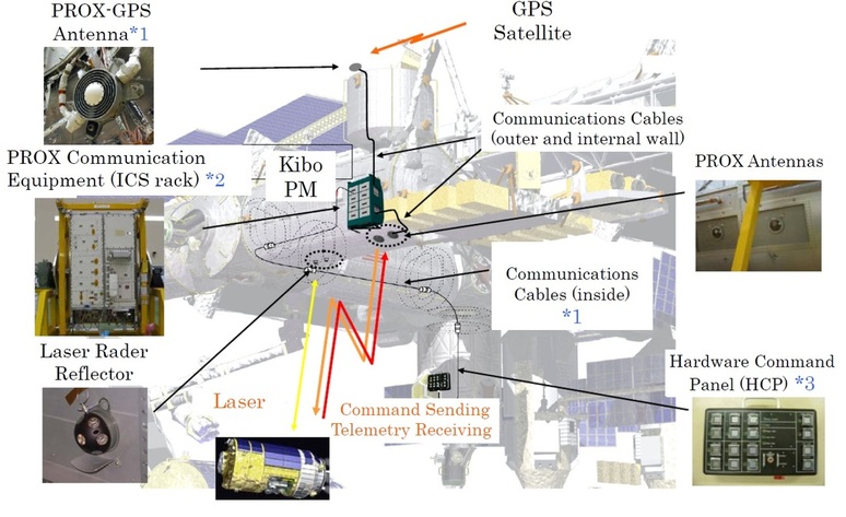
The HTV Proximity Communications System is used for the vehicle’s Rendezvous and Approach to the Space Station enabling the two Spacecraft, ISS and HTV, to engage in direct communications. The ISS portion of the PROX System is installed on the Kibo Module of ISS. The System uses relative GPS and Laser-Radar Rendezvous Sensors. The PROX equipment, such as transmitters, receivers, data handling processors, and GPS receivers are installed in the Inter-orbit Communication System (ICS) rack onboard Kibo’s Pressurized Module (PM).
GPS antennas are located on Kibo and the PM of HTV. Relative GPS enables the two spacecraft to constantly monitor the relative position of the spacecraft providing range and relative velocity data. For the close approach, HTV uses a Laser-Radar System for more refined range and velocity calculation. The Hardware Command Panel will be used by the ISS Crew to send commands to HTV while they are monitoring the Rendezvous and Approach Phase from the Robotics Work Station in the Cupola of ISS. Commands sent via the Command Panel include Hold commands to stop the approach and retreat commands to send HTV back to 30 meters or 100 meters to ISS.
Also, the crew can command the vehicle to abort the approach in case of any larger malfunctions occurring during the approach. The Free Drift Command disables all HTV Thrusters for the Robotic Arm to grapple the vehicle. When HTV arrives at the R-Bar, a point directly below ISS, the spacecraft switched to its Rendezvous Sensors bouncing laser beams off reflectors mounted on the Kibo Module to gather precise navigation data for the approach.
Mission Profile