H-IIB Launch Vehicle
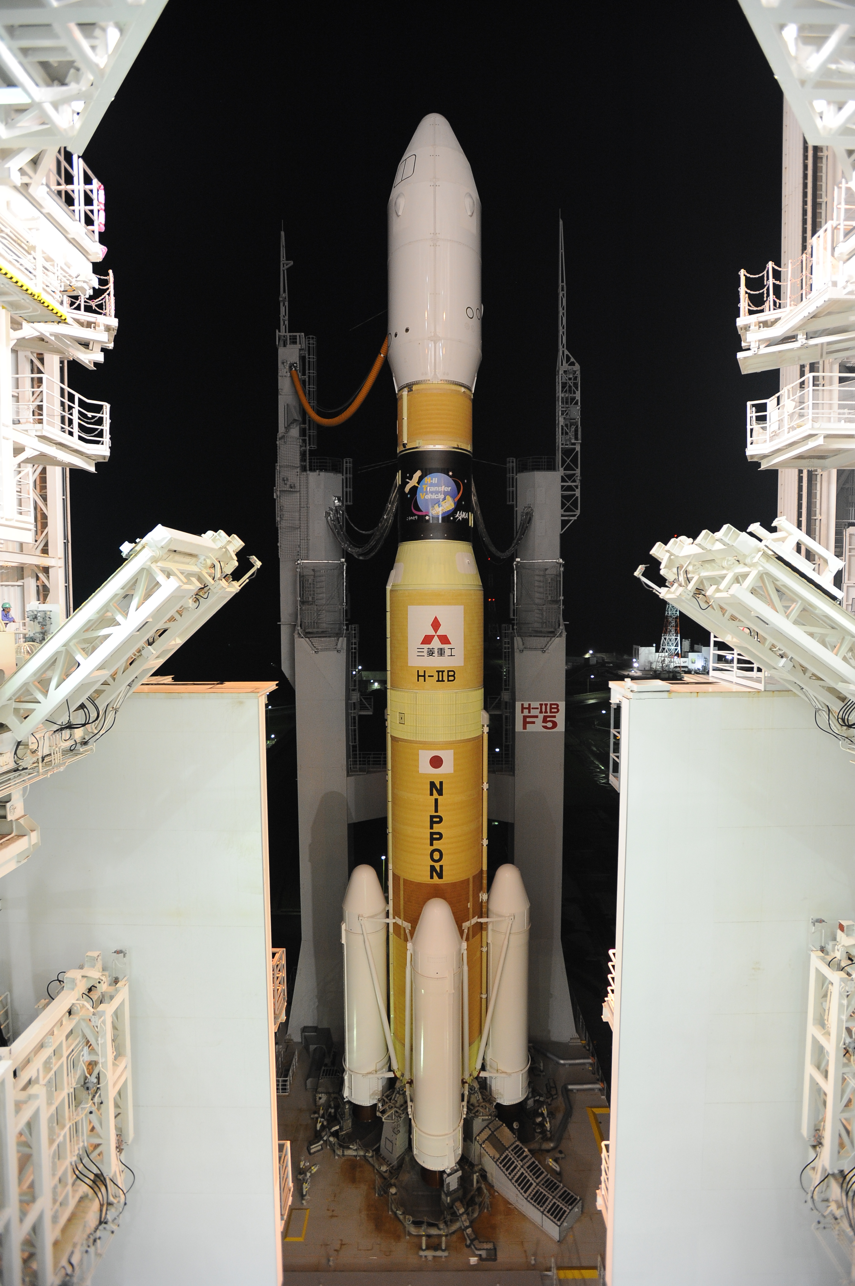
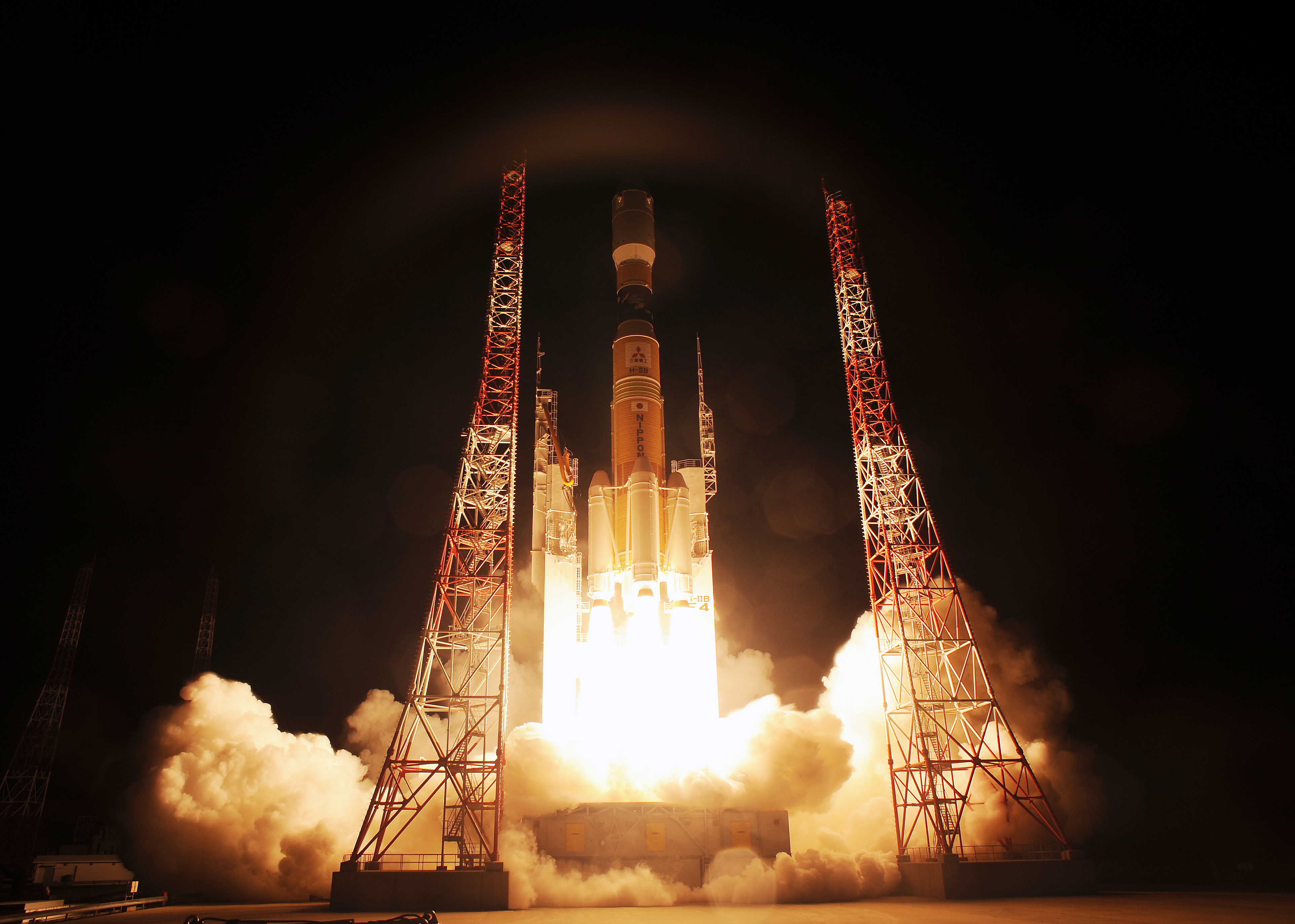
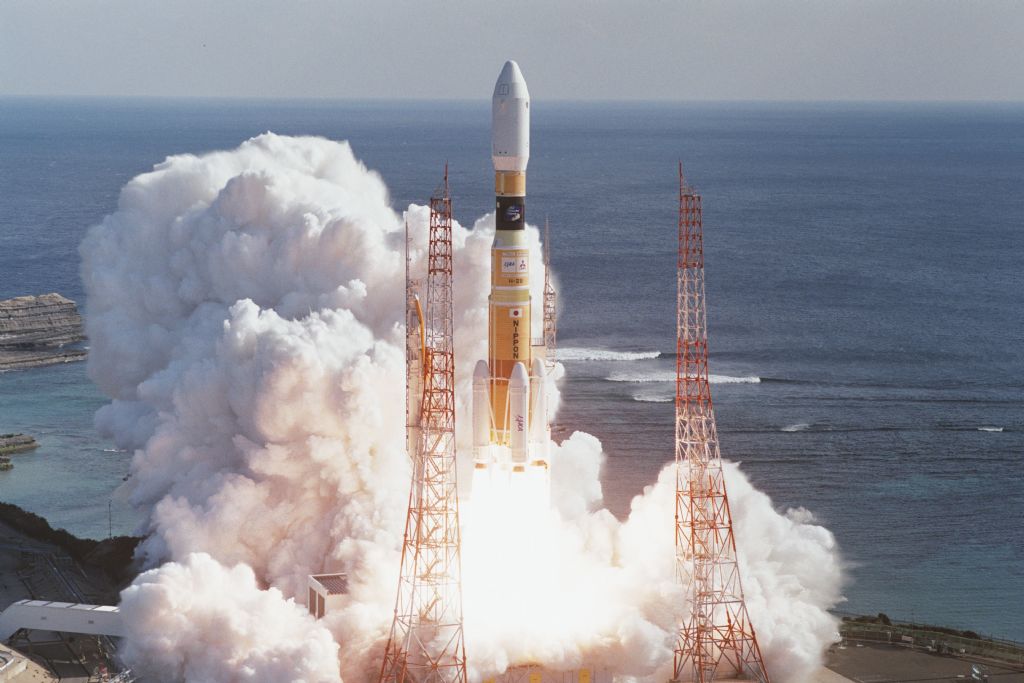
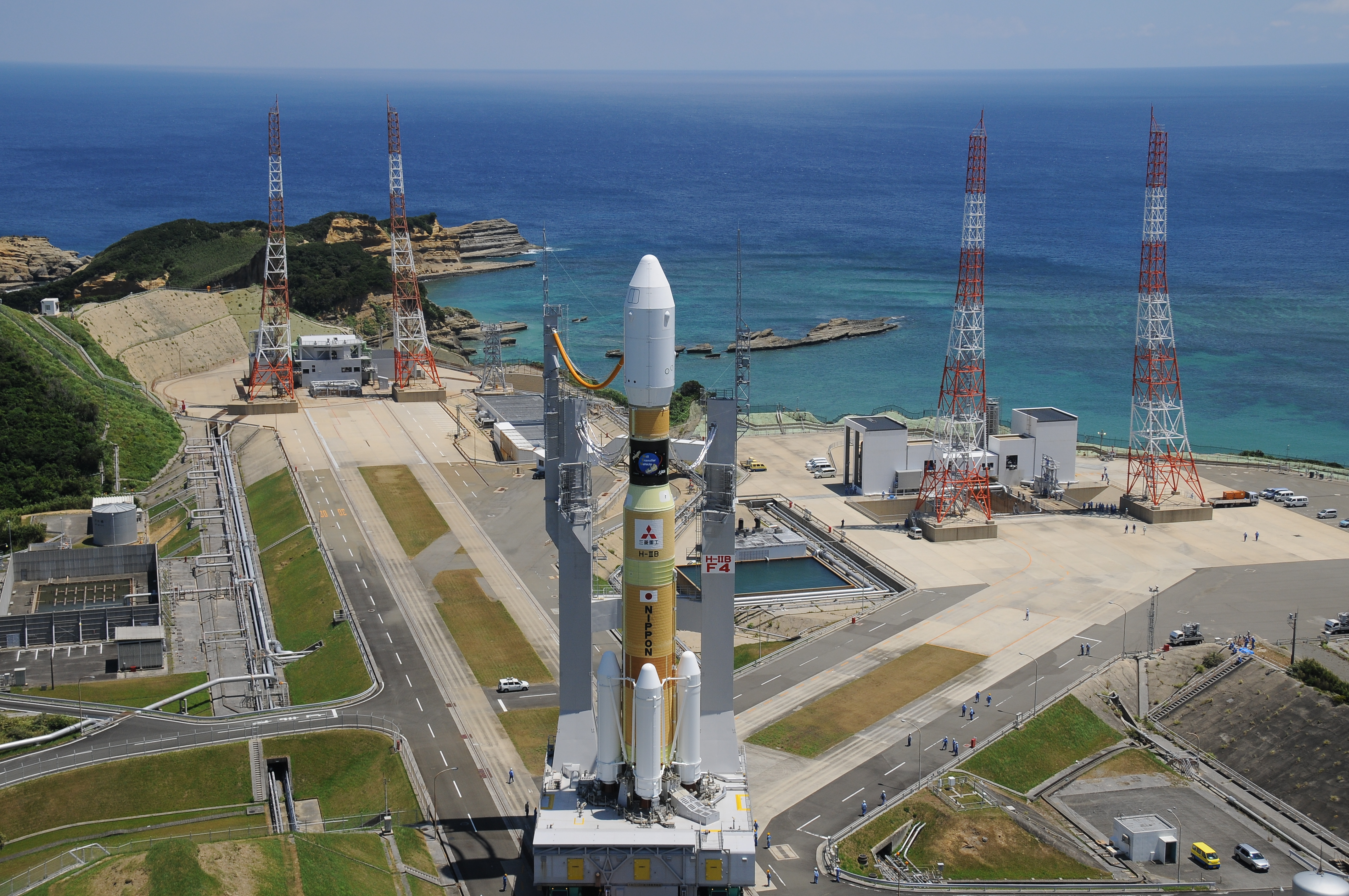
H-IIB is a Japanese Launch Vehicle. It is a two-stage rocket operated by the Japan Aerospace Exploration Agency and MHI. H-IIB is built by Mitsubishi Heavy Industries. The vehicle is a heavy lift launcher that can be used to deliver payloads to a variety of Orbits including Low Earth Orbit and Geostationary Transfer Orbit. The H-IIB is primarily used to launch the Japanese H-II Transfer Vehicle on Missions to resupply the International Space Station. The H-IIB Rocket is being launched from the Tanegashima Space Center, Japan. Current Launches are operated by JAXA and MHI with plans showing that MHI takes over the entire H-II family (H-IIA and H-IIB) as a contractor.
To date, H-IIB has completed 3 successful missions demonstrating its capabilities and delivering three HTVs to Low Earth Orbit. The Launcher made its maiden voyage in September 2009.
H-IIB is derived from the original H-II and the H-IIA that underwent extensive modifications to reduce costs and increase reliability and to increase its payload capacity for the heavy HTV. Unlike the H-IIA Launcher Family, H-IIB only flies in a single configuration. The Rocket features a core stage with four Solid Rocket Boosters installed on it that ignite at the moment of Liftoff and provide extra thrust for the initial portion of the mission. The H-IIB features a cryogenic second stage that takes over powered flight after the core stage burns out.
Flight proven components of the H-IIA series are also being used on the H-IIB Heavy Lift Launch Vehicle in order to reduce development cost and increase flight heritage and reliability for both launcher types. The development program of the H-IIB cost around 27 billion yen.
| Type | H-IIB |
| Manufacturer | Mitsubishi Heavy Industries |
| Operator | MHI/JAXA |
| Launch Site | Tanegashima Space Center |
| Height | 56.6m |
| Diameter | 5.2m |
| Launch Mass | 531,000kg |
| Stages | 2 |
| Boosters | 4 SRBs |
| Mass to LEO | 19,000kg |
| Mass to GTO | 8,000kg |
H-IIB Specifications
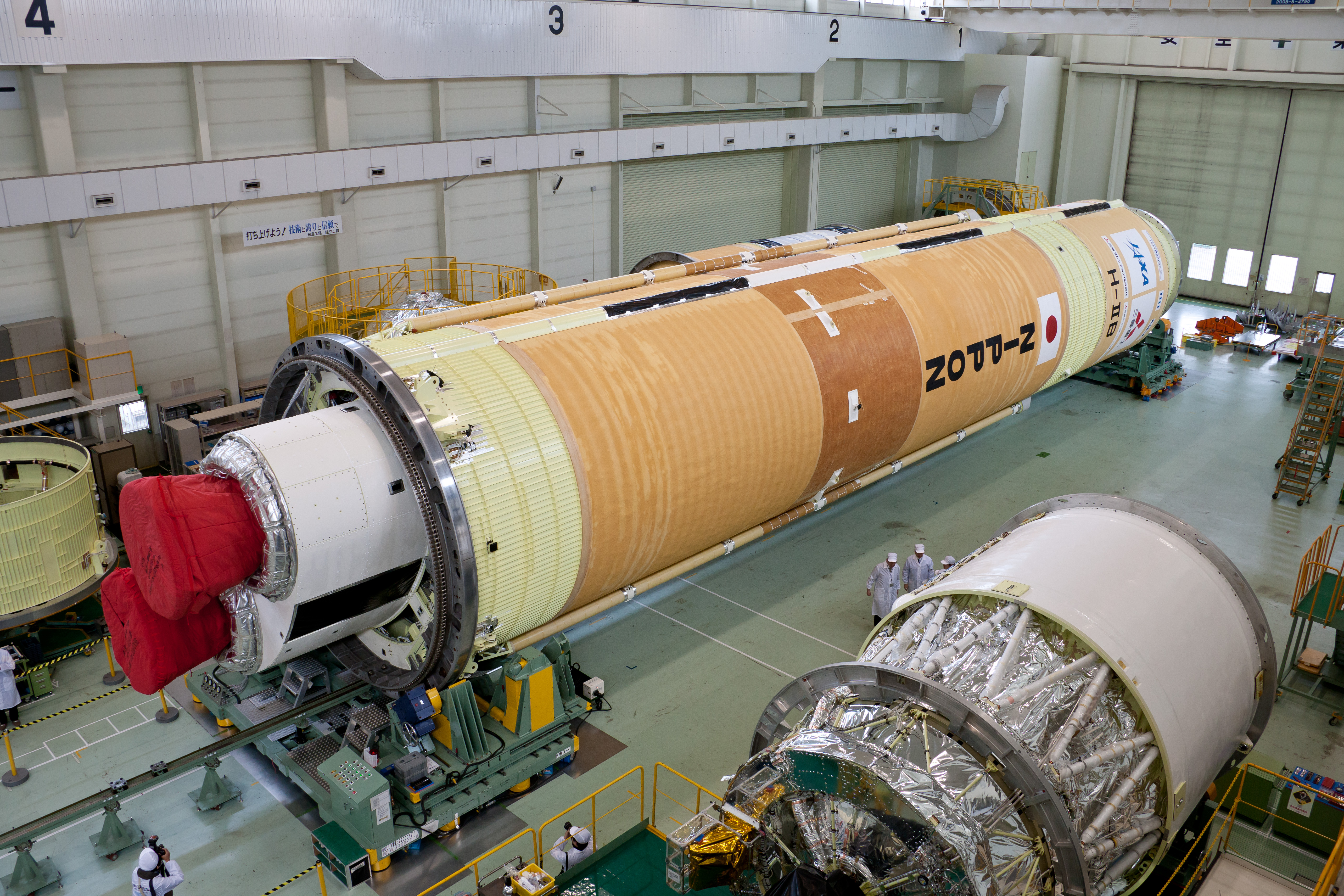
The H-IIB Launcher has a liftoff mass of 531,000 Kilograms and is 56.6 Meters in length. Unlike H-IIA, the H-IIB has an increased first stage diameter of 5.2 meters.
The second stage is identical with that of H-IIA featuring the nominal 4-meter diameter. The first and second stage use liquid Hydrogen and liquid Oxygen as propellants.
Four A3 Solid Rocket Boosters are clustered around the first stage and burn for the first 114 seconds of the flight providing 81% of Liftoff Thrust. The Launcher can lift payloads of up to 19,000 kilograms to Low Earth Orbit. Geostationary Transfer Orbit Capabilities are about 8,000 Kilograms.
| Diameter | 5.2m |
| Length | 38m |
| Propellant | Liquid Hydrogen |
| Oxidizer | Liquid Oxygen |
| Launch Mass | 202,000kg |
| Propellant Mass | 177,800kg |
| Tank Structure | Aluminum, isogrid |
| Guidance | From 2nd Stage |
| Propulsion | 2 LE-7A Engines |
| Engine Type | Staged Combustion |
| Propellant Feed | Turbopump |
| Thrust | 1,078kN |
| Total Thrust | 2,156kN |
| Engine Length | 3.4m |
| Engine Dry Weight | 1,714kg |
| Burn Time | 352sec |
| Specific Impulse | 349s (SL) 446s (Vac) |
| Chamber Pressure | 1,840psi (12.7MPa) |
| Nozzle Ratio | 52:1 |
| Restart Capability | No |
| Avionics | Guidance Computer, Gyros |
| Flight Termination, VHF Comms | |
| Lateral Acceleration Unit |
Core Stage
The first stage tank walls and domes are made from aluminum alloy and utilize reliable welding techniques to provide maximum strength. The first Stage of the H-IIB holds 70% more propellants than that of the H-IIA. It is 38 meters in length and 5.2 meters in diameter holding 177,800 Kilograms of Liquid Oxygen and Liquid Hydrogen.
Two LE-7A Engines power the first stage with a total thrust of 2,156 Kilonewtons. After engine ignition, the main engines are monitored for several seconds and good performance is verified before the vehicle is released and lifts off. An autonomous shutdown is conducted in case of off-nominal engine performance.
The LE-7A has dry mass of 1,714 Kilograms and a length of 3.4 meters. It has a nozzle ration of 1:52. First Stage Burn time is 352 seconds after which the stage separation mechanism is used to jettison the first stage. Thrust Vector Control is provided by gimbaling the engines.
The first stage has its own VHF communication system to send telemetry. Navigational Data is acquired with a Rate Gyro Package and a Lateral Acceleration Unit. The Rocket has a Flight Termination System consisting of two strings of transmitters, receivers and safe and arm devices. The FTS works with C-Band Communications and can be used to terminate the flight in case of any anomalies. The first stage has a Guidance Control Computer that is used to issue commands during the ascent phase
The interstage adapter between the two stages is a carbon fiber aluminum core composite structure.
| Type | SRB-A3 |
| Diameter | 2.5m |
| Length | 15.1m |
| Mass | 76,600kg |
| Propellant | Solid |
| Propellant Mass | 66,000kg |
| Motor Case | Monolithic Carbon-Fiber-Reinforced |
| Polymer | |
| Thrust | 2,305kN |
| Nominal Pressure | 11.1MPa |
| Burn Time | 114sec |
| Specific Impulse | 283.6s |
| Control | Electric MNT Vector Control |
Solid Rocket Boosters
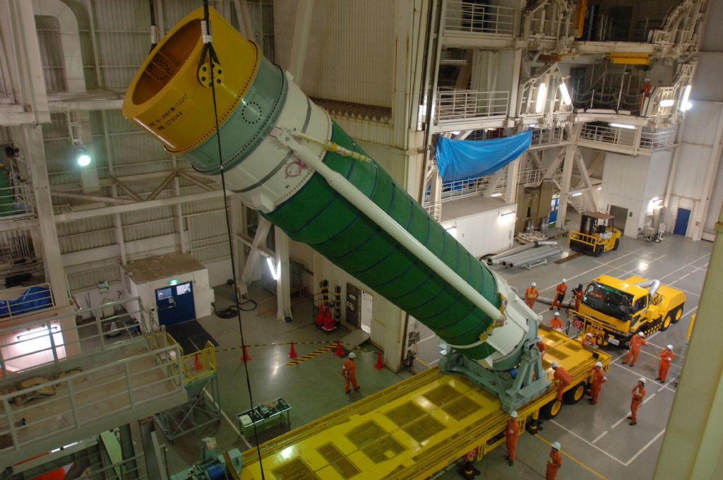
The H-IIB Launcher features four Solid Rocket Boosters designated SRB A3 that are ignited on the Ground and provide an additional amount of thrust for the first portion of the ascent.
Weighing 76,600 Kilograms, each SRB is 2.5 Meters in Diameter and 15.1 Meters long. The Boosters burn for the first 114 seconds of the flight and are jettisoned several seconds after burnout.
The Booster Motor Case consists of Monolithic Carbon Fiber Polymer. Each of the Boosters provides 2,305 Kilonewtons of thrust, all 4 are totaling for 9,220 Kilonewtons of thrust.
| Diameter | 4m |
| Length | 9.2m |
| Propellant | Liquid Hydrogen |
| Oxidizer | Liquid Oxygen |
| Tank Structure | Aluminum isogrid |
| Propellant Mass | 16,600kg |
| Propulsion | 1 LE-5B |
| Engine Type | Expander Bleed (Chamber) |
| Total Thrust | 137kN |
| Engine Diameter | 2.49m |
| Engine Length | 2.79m |
| Engine Dry Weight | 269kg |
| Burn Time | 499sec |
| Specific Impulse | 448s |
| Chamber Pressure | 519psi (3.58MPa) |
| Restart Capability | Up to 16 Starts |
| Ignition System | Spark Ignition |
| Avionics | Guidance Control Computer |
| Inertial Measurement Unit | |
| Flight Termination | |
| UHF Telemetry, C-Band Tracking |
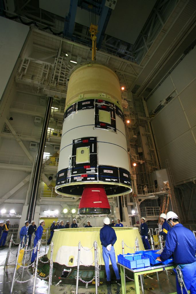
Second Stage
In essence, the tank assembly of the second stage of the H-IIB is simply a smaller version of the first stage’s design with a reduced diameter of 4 meters and a length of 9.2 meters.
One LE-5B engine powers the vehicle during second stage flight. The Engine is 2.79 meters in Diameter and has a nozzle diameter of 2.49 meters. Le-5B provides 137 Kilonewtons of thrust. It has a nominal burn time of 499 seconds, but is certified to burn for up to 40 minutes.
The engine can support up to 16 re-starts. During a nominal mission, the first burn of the second stage occurs after stage separations to place the vehicle in its preliminary Low Earth Orbit and a second burn later in the mission to increase the stack’s orbital altitude or circularize the Orbit in case of the HTV. After spacecraft separation, the second stage is able to make a Collision Avoidance Maneuver or deorbit burn.
The second stage accommodates most of the avionics of the Launcher. Flight computers and navigation system are redundant systems as part of a single-fault tolerant architecture. The Upper Stage is outfitted with a Reaction Control System. This system is used to control the vehicle’s attitude during coast phases. The Upper Stage is also equipped with a Flight Termination System.
Payload Fairing
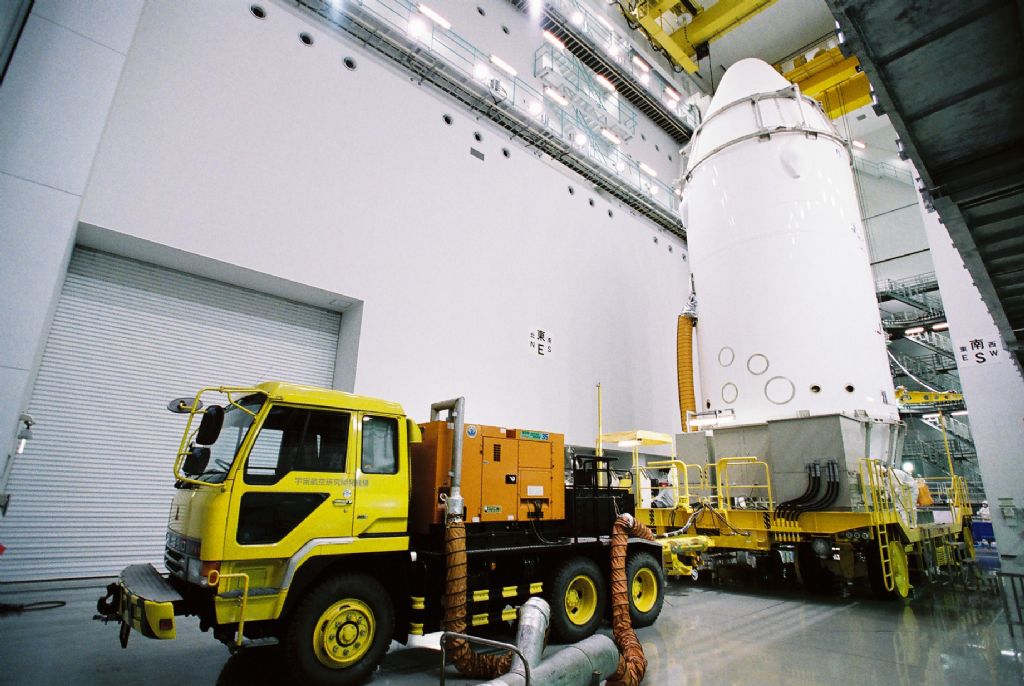
The Payload Fairing is positioned on top of the stacked vehicle and its integrated spacecraft. It protects the vehicle against aerodynamic, thermal and acoustic environments that the launcher experiences during atmospheric flight.
When the launcher has left the atmosphere, the fairing is jettisoned. The fairing then falls back to Earth. Separating the fairing as early as possible increases ascent performance.
H-IIB’s standard Fairing is 15 Meters long and 5.1 Meters in diameter. It weighs about 3,200 Kilograms. This fairing design is also used for the HTV to protect it during atmospheric flight. Custom fairing designs are available to accommodate a variety of payloads and customers.
Payload Adapter
Payload Adapters interface with the vehicle and the payload and are the only attachment point of the payload on the Launcher. They house equipment that is needed for Spacecraft Separation and ensure that the payload is secured during powered flight. Electrical and Communication connections are also part of the Adapter and route spacecraft Telemetry to the Flight Computers for downlink.