
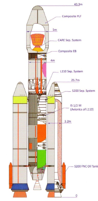
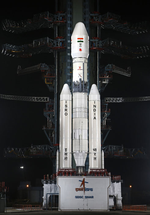
GSLV Mk. III Launch Vehicle
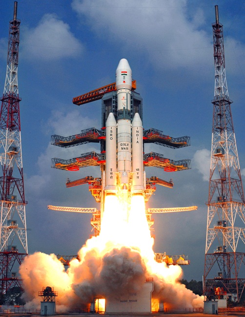
The GSLV Mk. III launch vehicle is an evolved version of India’s Geosynchronous Satellite Launch Vehicle, developed and operated by the Indian Space Research Organization. The primary purpose of GSLV is the deployment of Geostationary Satellites, but the vehicle has been designed to be human-rated to deliver an initial version of ISRO’s crewed vehicle into orbit.
The GSLV project was initiated in the 1990s when India determined that the country needed its own launch capability for Geosynchronous Satellites to become independent from other launch providers. At that time, India was relying on Russian rockets for heavy satellite launches. Missions were shifted when commercial launch providers such as Arianespace emerged and GSLV development continued.
In its initial stage, the GSLV project was to employ a large number of heritage components from the Polar Satellite Launch Vehicle that made its first flight in 1993. The three-stage GSLV Mk. I and Mk. II have an improved performance over the four-stage PSLV with the addition of strap-on liquid-fueled boosters and the cryogenic upper stage. GSLV Mk. III replaces the solid core stage with a large liquid-fueled core stage and twin Solid Rocket Boosters with a large cryogenic upper stage stacked on top.
Over the course of its development, GSLV flew in various configurations being designated Mk I a, b and c, and Mk II with Mk III being the successor to the first generation of GSLV launchers scheduled to make its first flight in 2014.
Development of the GSLV Mk. III was initiated in the early 2000s with a first launch expected within one decade, a target that could not be kept due to the struggle of the other GSLV variants encountered between 2001 and 2010.
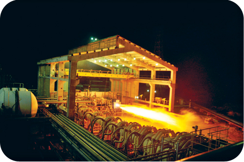
Testing on a component scale began early in the development process of the launcher and a number of components and manufacturing techniques had already been established as part of the PSLV and earlier GSLV program. The S200 Solid Rocket Booster started static fire testing in 2010 at a test facility that used to handle tests of the smaller S139 PSLV core stage requiring a number of upgrades to be made before the first S200 test. The first test achieved all of its objectives and another successful test was conducted in 2011.
The L-110 core stage performed its first full-scale test in March 2010. 150 seconds into a targeted 200-second burn of the two Vikas engines, the test was terminated due to a leak observed on the stage. A second test in September of that year achieved its planned duration and accomplished all test objectives.
The most difficult component of the GSLV Mk. III to be developed was the large C-25 Cryogenic Upper Stage. Development of India’s first indigenous cryogenic stage led to a delay of the GSLV Mk. II vehicle and thus Mk. III was pushed back further. The new CE-20 Cryogenic Engine completed its initial cold flow test in October 2014 ahead of initiating test firings that will lead up to full-duration tests before the upper stage will be ready for flight in 2017.
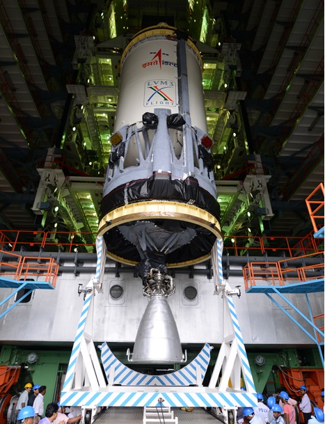
The GSLV Mk. III launch vehicle made its first test flight in December 2014 using fully operational Solid Rocket Boosters and Core Stage, but since the Cryogenic Upper Stage and its CE-20 engine are not ready before 2017, the flight hosted an Upper Stage Mass Simulator. The simulator included 25 metric tons of simulated propellant to mimic the behavior of the upper stage during the early stages of flight to create realistic conditions that would be encountered in an operational mission.
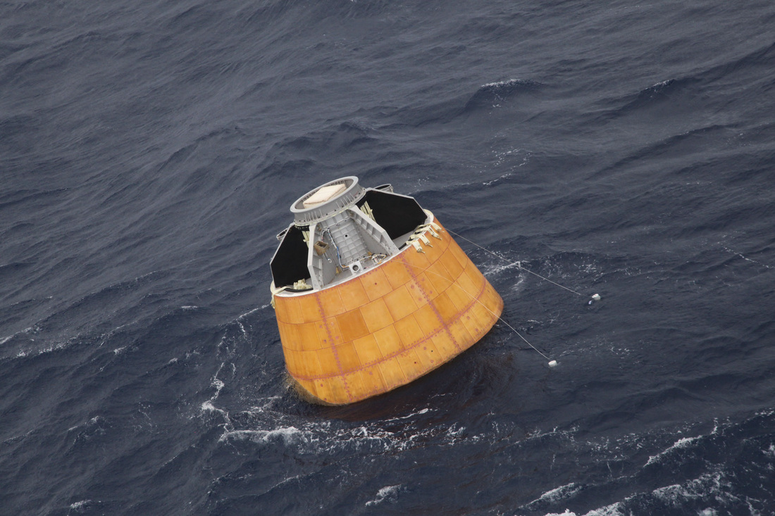
The mission flew a Structural Model of ISRO’s Crew Module on a sub-orbital trajectory for a test of basic systems of the crew module including the structural frame, part of its avionics, the heat shield and parachute system. The 19-minute flight carried the 3,735-Kilogram vehicle to an altitude of 126 Kilometers before re-entering the atmosphere at a speed of 5.3 Kilometers per second ahead of a parachute-assisted splashdown in the sea near the Andaman Islands.
The crew module simulator measures 3.1 meters in diameter and 2.68 meters in length, matching the planed dimensions of India’s three-person space capsule. After separation from the launch vehicle at an altitude of about 126 Kilometers at T+5 minutes 25 seconds, the CM will employ active control to dampen any body rates and enter a stable position for re-entry with its heat shield facing the direction of travel. Re-Entry into the atmosphere is accomplished in a ballistic mode with a peak temperature of 1,600°C to deliver the vehicle to a point for the jettisoning of its Forward Cover to expose the parachute system about 15 Kilometers in altitude for splashdown 19 minutes after liftoff.
GSLV Mk. Ia made its first development flight on April 18, 2001 using a smaller core stage and a Russian-built Cryogenic Upper Stage since the indigenous Indian Cryogenic Upper Stage was still in development. The mission was only partially successful, reaching a lower-than-planned orbit due to a shortfall in performance either caused by the vehicle’s guidance system or a premature shutdown of the third stage. The GSAT-1 payload attempted to raise its orbit on its own, but failed to do so because of a design flaw in its propulsion system.
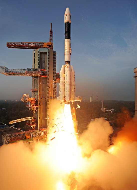
The next two flights, performed by GSLV Mk. Ia and Ib with the full-size Core Stage, were successful, delivering the GAST-2 and 3 satellites to orbit. On its next flight in July 2006, GSLV suffered a failure early in flight when one of its boosters malfunctioned requiring the destruction of the rocket by Range Safety Personnel. The INSAT-4C payload and remains of the launcher crashed into the Bay of Bengal.
GLSV Mk. II made its next flight in 2007 and successfully reached orbit, but a fault in its Flight Control System guided the vehicle into a lower orbit at a higher inclination which required the INSAT-4CR spacecraft to correct its orbit.
GSLV Mk. II with a fully operational Indian-built upper stage flew for the first time in April 2010 and failed due to a malfunction of said upper stage. Late in the mission, the Fuel Booster Turbo Pump on the third stage encountered a problem that led to the loss of the GSAT-4 satellite. The Mk. Ic variant of the GSLV with a 15,000kg propellant load on the third stage flew in December 2010 and marked another failure as the vehicle was destroyed by the Range Safety Officer after a loss of control that was the result of a structural failure.
Having encountered abundant failures across all systems of the launch vehicle, GSLV was grounded for a top-to-bottom review of its various systems. Improvements were made to the launcher’s guidance system, the upper stage and a number of structural components to increase the reliability of the rocket. GSLV Mk. II returned to flight in January 2014 and achieved a completely successful mission, delivering the GSAT-14 satellite into a Geostationary Transfer Orbit.
GSLV Mk. II will continue flying at a rate of one or two per year while the Mk. III version is still in development.
GSLV Mk. III Specifications
| Type | GSLV Mk. III |
| Length | 43.43m |
| Core Diameter | 4.0m |
| Launch Mass | 630,600kg |
| Boosters | 2 x S200 |
| Stage 1 | L-110 |
| Stage 2 | Indian Cryogenic Upper Stage |
| Mass to LEO | 10,000kg |
| Mass to GTO | 5,000kg |
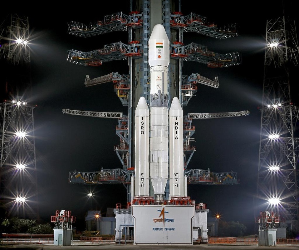
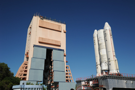
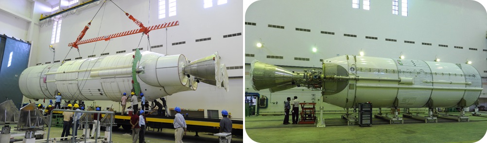
The GSLV Mk. III launch vehicle stands 43.4 meters tall consisting of a large Core Stage using liquid propellants with two Solid Rocket Boosters attached to it.
Stacked atop the core is a larger version of India’s Cryogenic Upper Stage, powered by the most powerful cryogenic engine built in India to date. GSLV Mk. III has a launch mass of approximately 630,600 Kilograms.
The launcher can deliver payloads of up to ten metric tons into Low Earth Orbit and up to 5,000 Kilograms into a Geostationary Transfer Orbit.
Solid Rocket Boosters
| Type | S200 |
| # Boosters | 2 |
| Length | 26.2m |
| Case Diameter | 3.20m |
| Nozzle Diameter | 3.27m |
| Propellant | Solid – HTPB-Based |
| Inert Mass | 31,300kg |
| Propellant Mass | 206,690kg |
| Launch Mass | 238,000kg |
| Case Material | Steel |
| # Segments | 3 |
| Engine Type | S200 LSB |
| Peak Thrust (SL) | 5,151kN |
| Avg. Thrust (SL) | 3,578.2kN |
| Specific Impulse SL | 227s |
| Specific Impulse Vac | 274.5s |
| Max. Pressure | 56.92bar |
| Average Pressure | 39.90bar |
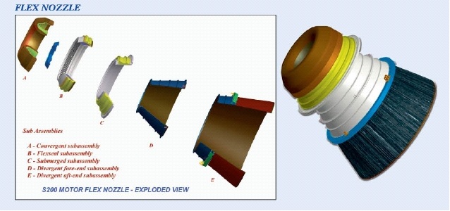
| Control | Flex Nozzle Gimbaling |
| Flex Nozzle Length | 3.474m |
| Throat Diameter | 0.886m |
| Area Ratio | 12.1 |
| Thrust Vector Ctrl | Hydro-Pneumatic Pistons |
| Vector Capability | +/-5.5° |
| Slew Rate | 10°/s |
| Actuator Load | 294kN |
| Burn Time | 130s |
| Separation | 149s |
| Booster Separation | Pyrotechnics, Jettison Motors |
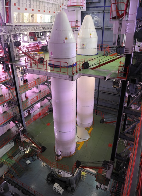
GSLV Mk. III uses two S200 solid-fueled boosters that are attached to the Core Stage and deliver thrust for the initial portion of the flight.
Also known as LSB (Large Solid Booster), each of the S200 boosters stands 26.2 meters tall and consists of three segments holding a total of 206,690 Kilograms of propellant.
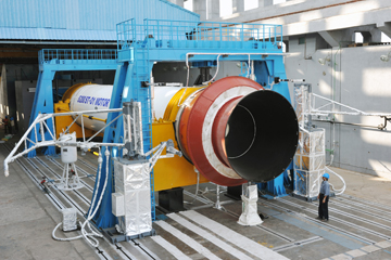
The booster casing is 3.2 meters in diameter while the Flex Nozzle at the base of the booster is 3.27 meters in diameter.
S200 is the third largest Solid Rocket Booster used in any launch vehicle after the Space Shuttle and the Ariane 5 rocket. Like these two other vehicles, S200 uses a HTPB-based propellant (Hydroxyl-terminated Ploy-butadiene).
Major components of the S200 Solid Rocket Booster are the Flex Nozzle, the motor case, the propellant, igniter and nose cone.
The booster itself consists of three steel segments – the head-end segment contains 27,100kg of propellant, the middle segment carries 97,380kg and the Nozzle-end segment is loaded with 82,210kg of propellants.
S200 is ignited by a highly reliable pyrogen igniter that is initiated by a secondary add on pyrogen igniter which generates enough hot particles to travel down the length of the booster to ignite the propellant.
The igniter is based on that used on the S139 first stage of the PSLV and GSLV Mk. II launch vehicles.
It is triggered through a redundant safe and arm device that initiates explosive transfer assemblies.
The Flex nozzle at the base of the booster is divergent to direct the gas flow from the chamber.
S200 uses a nozzle with a throat diameter of 88.6 centimeters and an area ratio of 12.1. The Flex Nozzle assembly has a length of 3.58 meters consisting of a convergent subassembly, a flexseat subassembly, a submerged subassembly, a divergent fore-end subassembly and a divergent aft-end subassembly.
For vehicle control, the Flex Nozzle can be vectored using two electro-hydraulic servo actuators. This planar movement provides pitch and yaw control and, in combination with the other S200 booster, can be used for roll control as well.
The Flex Nozzle Control system is capable of slewing the nozzle by up to 5.5 degrees in either direction of the actuation plane with a maximum slew rate of 10°/s. The actuator has a capacity of 294 Kilonewtons using a hydro-pneumatic pistons operated in blow down mode by high-pressure oil and nitrogen.
The actuation system is housed in a flared base shroud installed on the booster that also builds the interface to the Mobile Launch Platform. The boosters use a dual redundant control unit with FDI logic.
The S200 boosters are designed to operate at a fixed pressure and thrust profile (M-type) with a maximum thrust of 5,151 Kilonewtons (sea level) and a average SL thrust of 3,578kN corresponding to chamber pressures of 56.9 and 39.9 bar.
S200 operates for 130 seconds and is separated from the launch vehicle at T+149 seconds using pyrotechnic separation devices and six small solid-fueled jettison motors located in the nose and aft segments of the boosters.
Core Stage

| Type | L-110 |
| Length | 21.39m |
| Diameter | 4.0m |
| Fuel | Unsymmetrical Dimethylhydrazine |
| Oxidizer | Nitrogen Tetroxide |
| Inert Mass | 10,600kg |
| Propellant Mass | 115,000kg |
| Launch Mass | 125,600kg |
| Propellant Tanks | Aluminum Alloy |
| Fuel | UH25 – 75% UDMH, 25% Diazane |
| Oxidizer | Nitrogen Tetroxide |
| Propulsion | 2 Vikas 2 |
| Thrust (SL) | 677kN |
| Thrust (Vac) | 766kN |
| Specific Impulse | 293 sec |
| Engine Dry Weight | 900kg |
| Engine Length | 2.87m |
| Engine Diameter | 0.99m |
| Chamber Pressure | 58.5bar |
| Mixture Ratio | 1.7 (Ox/Fuel) |
| Turbopump Speed | 10,000rpm |
| Flow Rate | 275kg/s |
| Area Ratio | 13.88 |
| Attitude Control | Engine Gimbaling |
| Ignition | T+110s |
| Burn Time | 200s |
| Stage Separation | Active/Passive Collets |
The GSLV Mk. II launch vehicle features a large Core Stage powered by two Vikas engines.
Designated L-110, the core stage stands 21.39 meters tall and has a diameter of four meters, capable of holding about 110 metric tons of hypergolic propellants for consumption during a burn of 200 seconds.
GSLV Mk. III launches only powered by its two Solid Rocket Boosters, the core stage is launched with its engines turned off, protected by covers.
Around 110 seconds into the flight, 20 seconds ahead of booster burnout, the two engines of the core stage are ignited.
The core stage hosts two large aluminum propellant tanks that hold a total of 115,000 Kilograms of hypergolic propellants – Nitrogen Tetroxide Oxidizer and UH25 fuel – a mixture of 75% Unsymmetrical Dimethylhydrazine and 25% Hydrazine Hydrate. UH-25 is employed because it has shown to limit combustion instability when compared with UDMH alone.
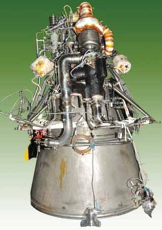
Two Vikas 2 engines are installed on the Core Stage. Vikas 2 is a version of the Viking engines that were used aboard the European Ariane 1 to 4 launch vehicles.
The engines were developed in the 1970s and India obtained a license to manufacture the engines. The Vikas engines built by the Indian Space Research Organization are lightly modified Viking 2 engines.
Each Vikas 2 engine measures 2.87 meters in length and 0.99 meters in diameter with an empty weight of around 900 Kilograms. The turbopump-fed engine operates at a chamber pressure of 58.5 bar with an oxidizer to fuel ratio of 1.7. Vikas 2 delivers 677 Kilonewtons of sea level thrust increasing to 766kN in vacuum conditions, giving L-110 a total thrust of 1,532kN (156,200 Kilogram-force).
Each Vikas engine on the Core Stage can be gimbaled individually to allow control in pitch, yaw and roll. Separation of L-110 is accomplished using an active/passive collet system.
Cryogenic Upper Stage
| Type | C-25 Cryogenic Upper Stage |
| Length | 13.55m |
| Diameter | 4.0m |
| Fuel | Liquid Hydrogen |
| Oxidizer | Liquid Oxygen |
| Inert Mass | 5,000kg |
| Propellant Mass | 28,000kg |
| Launch Mass | 33,000kg |
| Propellant Tanks | Aluminum Alloy |
| Propulsion | CE-20 |
| Engine Type | Gas Generator |
| Thrust – Vacuum | 200kN |
| Operational Range | 180-220kN |
| Specific Impulse Vac | 443s |
| Engine Mass | 588kg |
| Chamber Pressure | 60bar |
| Mixture Ratio | 5.05 |
| Area Ratio | 100 |
| Thrust to Weight | 34.7 |
| Burn Time | 640s |
| Guidance | Inertial Platform, Closed Loop |
| Attitude Control | 2 Vernier Engines |
| Restart Capability | RCS for Coast Phase |
Starting with the second mission of GSLV Mk. III, the launcher will feature a Cryogenic Upper Stage carrying up to 28,000 Kilograms of Liquid Oxygen and Liquid Hydrogen. This upper stage is a larger version of the third stage of the Mk. II using a more powerful version of the Indian Cryogenic Engine. The upper stage measures about 13.55 meters in length and 4 meters in diameter with an inert mass on the order of five metric tons.
The third stage of the GSLV Mk. III is powered by a CE-20 cryogenic engine that is based on the CE-7.5 of the GSLV Mk. II, but delivers a much higher thrust of 200 Kilonewtons.
The engine is an open-cycle Gas Generator engine which uses a small fraction of the fuel and oxidizer flow from the turbopumps to burn it in a Gas Generator that delivers the high-pressure gas needed to drive the turbopumps of the fuel and oxidizer. The propellants are then injected into the combustion chamber where they are burned to generate thrust while the gas generator exhaust is ejected through a nozzle and not burned in the chamber.
The CE-20 engine operates at a fixed thrust level that can be set to 180 to 220 Kilonewtons. It operates at a mixture ratio of 5.05 and a nominal chamber pressure of 60 bar to achieve a specific impulse of 443 seconds.
The engine has a dry mass of about 588 Kilograms and uses an extended nozzle with an area ratio of 100 for optimized operation in vacuum. The engine provides re-start capability and operates up to 640 seconds in a nominal GSLV Mk. III flight.
Vehicle control during burns is provided by two vernier engines that can be swiveled in all directions to provide three-axis control. During Coast Phases, a cold gas reaction control system is used for vehicle stabilization and re-orientations. The spacecraft is separated by a tension release device mounted at the separation interface with the third stage.
The third stage of the launch vehicle also houses the flight computers and the inertial guidance platform of the GSLV. The control system was developed and built in India. GSLV uses a Redundant Strap Down Inertial Navigation System/Inertial Guidance System that is housed in the equipment bay of the third stage. The digital control system of the launcher uses closed-loop guidance throughout the flight to ensure accurate injections into the target orbit.
Also mounted on the third stage is the communications system of the launch vehicle consisting of an S-Band system for telemetry downlink and a C-Band transponder that allows radar tracking and preliminary orbit determination.
The communications link is also used for range safety / flight termination that uses a dedicated system that is located on all stages of the vehicle and features separate avionics.
Payload Fairing
 The Payload Fairing, or “Heat Shield” as ISRO refers to it, is positioned on top of the stacked vehicle and its integrated Payload. It protects the spacecraft against aerodynamic, thermal and acoustic environments that the vehicle experiences during atmospheric flight. When the launcher has left the atmosphere, the fairing is jettisoned by pyrotechnical initiated systems. Separating the fairing as early as possible increases launcher performance.
GSLV Mk. III offers a large fairing with a five-meter diameter to provide sufficient room even to large satellites and spacecraft. Fairing separation in a nominal flight scenario occurs at approximately T+253 seconds. The fairing is made of Aluminum Alloy featuring acoustic absorption blankets.
Separation is accomplished by a linear piston cylinder separation and jettisoning mechanism (zip cord) running along the full length of the PLF and a clamp and joint at the base of the fairing. Both systems are pyrotechnically initiated. The gas pressure generated by the zip cord expands a rubber bellow that pushes that piston and cylinder apart, pushing the fairing halves laterally away from the launcher.
