
GPM Core – Mission & Spacecraft Overview
The Global Precipitation Measurement is a worldwide multi-agency effort led by NASA and JAXA with the goal of establishing a satellite constellation to acquire global precipitation measurements every two to four hours. For that, the project coordinates instruments on several satellites operated by a number of agencies orbiting Earth at different altitudes and inclinations. The project builds on the Tropical Rainfall Measuring Mission that is expanded to global coverage in order to provide high quality global rain maps.
The objectives of the mission include the near-global measurement of precipitation, its distribution, cloud dynamics, rainfall processes and associated physical processes. These information provide insight into the global water cycle that is important in the study of climate change. Additional benefits of GPM include improvements in weather and precipitation prediction models, more advanced water resource prediction as well as models for for the prediction of flood hazards and fresh water management. Understanding the horizontal and vertical structure of rainfall and its different microphysical properties and achieving a high global sampling rate are key objectives of GPM.
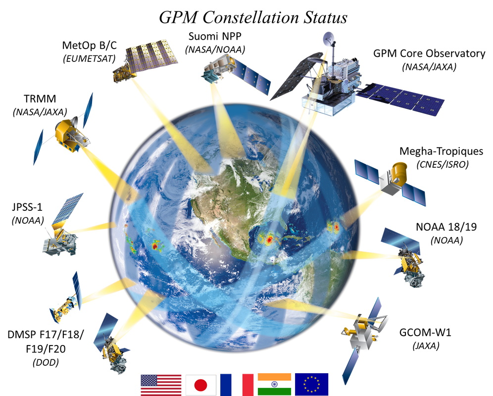
The Global Precipitation Measurement project uses data from the following spacecraft (not all launched yet):
- Special Sensor Microwave Imagers/Sounders deployed on four Defense Meteorological Satellite Program Satellites operated by the US Department of Defense
- The Advanced Microwave Scanning Radiometer 2 on the GCOM-W1 Satellite operated by JAXA
- The Multi-Frequency Microwave Scanning Radiometer & multi-channel microwave humidity sounder on the Megha-Tropiques spacecraft operated by ISRO and CNES
- The Microwave Humidity Sounder on the NOAA-19 Satellite
- The Microwave Humidity Sounder on the MetOp A/B/C Satellites operated by EUMETSAT
- The Advanced Technology Microwave Sounder on the Suomi NPP Satellite and NOAA-NASA Joint Polar Satellite System satellites
- A microwave imager installed on Defense Weather Satellite System spacecraft
Also part of the mission will be extensive data gathered by rainfall detectors and Earth-based sensors deployed at hundreds of locations to provide additional information and data points for instrument calibration.
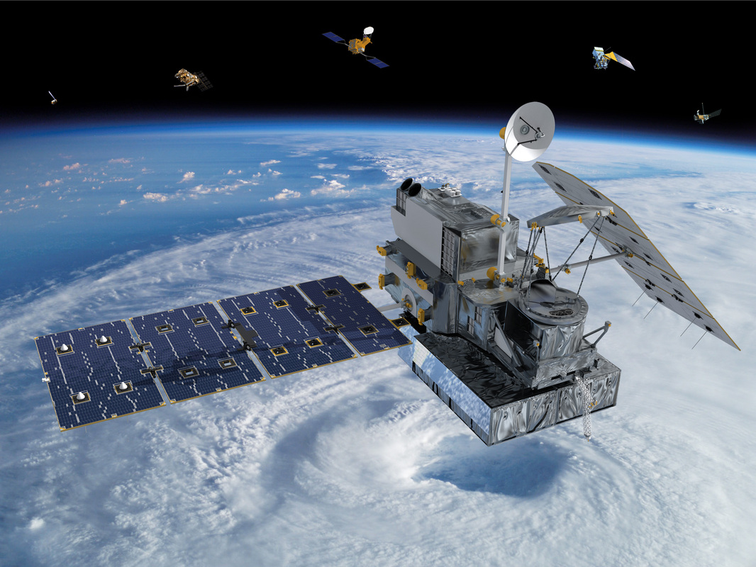
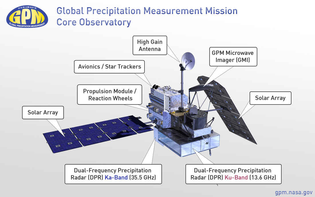
The center of the GPM project is the Core Spacecraft that hosts two instruments, the Dual-Frequency Precipitation Radar and the GPM Microwave Imager. The Core Spacecraft acquires accurate rainfall measurements, information on cloud dynamics and rainfall processes and more importantly, it serves as a calibration reference required to collect consistent data using all the different satellites and instruments deployed across the constellation. The Core Spacecraft is launched atop an H-IIA 202 Rocket in February 2014 to mark the start of the GPM project.
GPM Spacecraft Overview
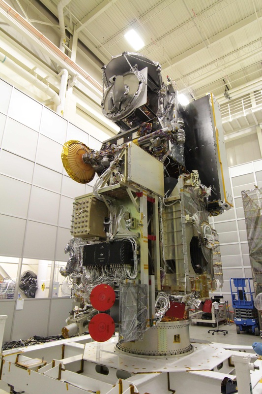
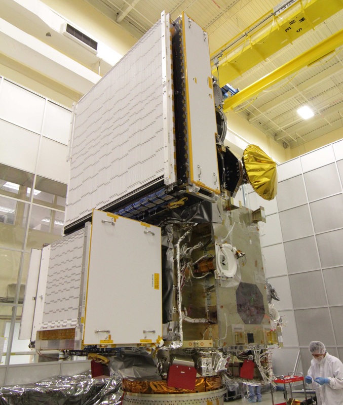
The GPM core spacecraft uses an aluminum and composite structure to facilitate the different systems and payloads. The spacecraft is 11.6 by 6.5 by 4.9meters in size with a launch mass of 3850 Kilograms.
Electrical Power System
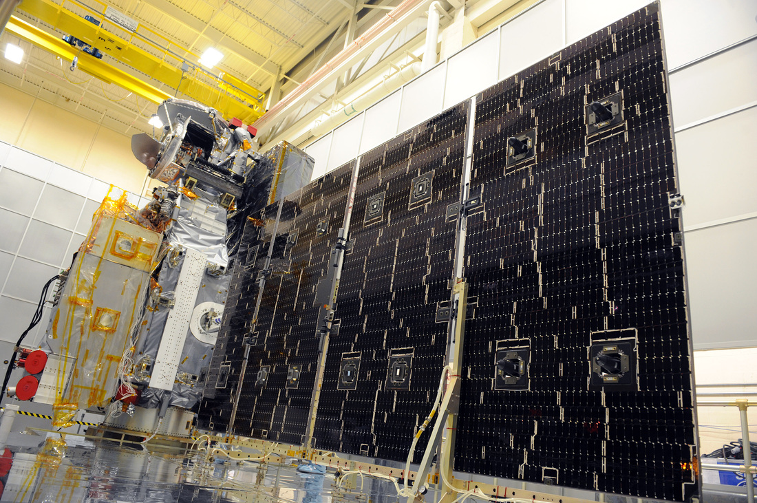
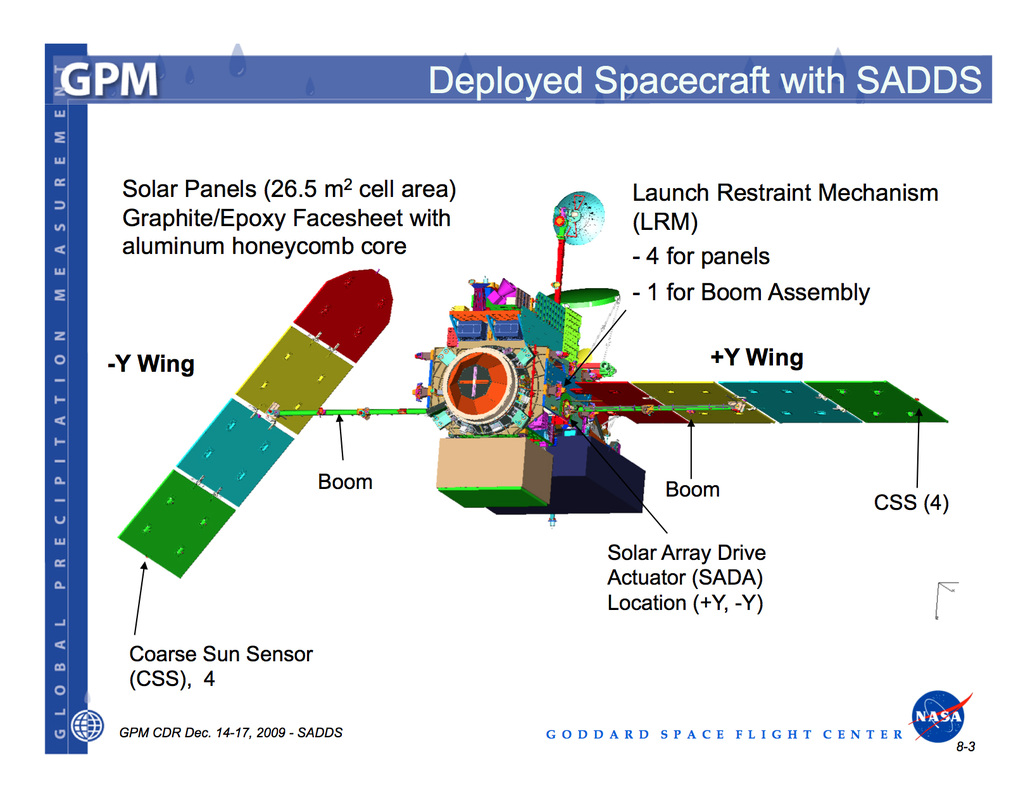
The GPM spacecraft is equipped with two solar arrays with four panels on each array. The arrays are attached to booms that interface with the second panel in order to individually tilt the arrays to track the sun and optimize power generation. Each panel features 800 to 1,200 individual Gallium-Arsenide solar cells. Coarse sun sensors are installed on the arrays to provide guidance for array tilting to achieve optimal illumination. Generally, CSS are imagers with a field of view of 85 degrees to determine sun direction with an error of ten degrees.
Power from the arrays is passed to a suite of power controllers facilitated in a single Power System Electronics Box to distribute electrical power to the different systems and payloads that use a regulated, redundant power bus at 28 Volts with an operational range of 23 to 35 V. A dedicated controller is used to regulate the state of charge of a single 200 Amp-hour Li-Ion battery. Overall, GPM generates 1,950 Watts of End of Life Power.
Thermal Control System
Like most spacecraft, GPM uses a combination of active and passive thermal control. Passive thermal control is accomplished by the use of thermal covers, coatings and multilayer insulation that prevents sunlight from excessively heating the satellite and heat from dissipating into space in darkness. The outer layer of the multilayer insulation is used to minimize heat loss and is also designed to protect the spacecraft against corrosion by atomic oxygen and electrical charging. The outer MLI layer is made of Germanium Black Kapton. GPM uses blanket tents and form-fitting blankets to protect most of its non-radiating surfaces.
Active thermal control uses heat rejection systems as well as heaters and temperature sensors to keep the satellite at an operating temperature. Because all electronics of the satellite generate heat, GPM has to be outfitted with a heat rejection system. Most electronic components of the spacecraft reject heat through their baseplates that are mounted on structural surfaces using a thermal interface material to improve the heat transfer. The heat is then transported via constant conductance heat pipes – the Avionics Module uses one U-shaped and one S-shaped heat pipe while the Power System Electronics Box has two L-shaped heat pipes. The battery assembly has four dedicated heat pipes.
Heat is rejected via radiators installed on the +Y side of the spacecraft that never faces the sun during nominal mission operations. These high-emittance radiators include an avionics radiator, a pocketed battery radiator, a Lower Bus Structure Radiator, dedicated radiators for the two solar array drive assemblies and separate radiators for the RF communications system.
Thermocouples provide temperature data of various systems to the satellite’s control system that then actuates heaters if necessary to maintain operational or survival temperatures of components depending on the currently set flight mode.
Propulsion System
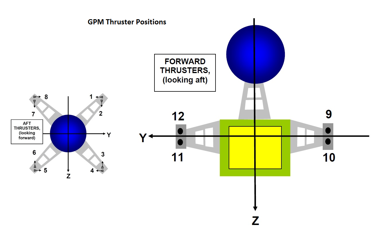
The GPM Core spacecraft uses a chemical propulsion system for attitude control, reaction wheels momentum dumps and to maintain its Low Earth Orbit. A total of 12 thrusters are installed on the spacecraft.
Eight of those 12 thrusters are installed on the aft section of the satellite while the remaining four thrusters are installed on the forward-facing section. Four thrusters have 90-degree nozzles, the other eight have straight nozzles. All thrusters are used for attitude control and momentum dumps while orbital maneuvers only use the four forward thrusters that are facing the same direction.
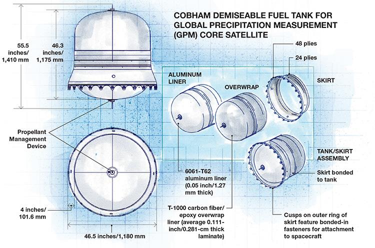
The propulsion system utilizes high-purity Hydrazine fuel that is stored in a single Composite Overwrap Pressure Vessel tank. It uses an outer shell made of graphite composite, a tank skirt consisting of graphite composite with metallic inserts and an Aluminum 6061 alloy liner. The tank is filled with 545 Kilograms of Hydrazine at launch pressurized to 27.6 bar. The tank has been designed to operate at pressures of up to 34.5 bar and a burst pressure of 55.2 bar. The minimum flight pressure is 6.8 bar. The tank has been built to maintain a temperature of 2 to 50 degrees Celsius with a ten-year minimum storage life of the hydrazine inside without performance degradation. Tank pressurization is accomplished using 6.2 Kilograms of high-pressure Nitrogen.
The thrusters generate thrust by the catalytic decomposition of hydrazine propellant using heated platinum/palladium catalyst beds. Operated in blowdown mode, the thrusters provide a maximum thrust of 44.5 Newtons at a feed pressure of 27.6 bar and 13.3 Newtons at 6.8 bar feed pressure. Operation of the thrusters is accomplished in pulse mode for attitude control and steady-state mode for orbital maneuvers. The minimum pulse duration of the thrusters is less than 50 milliseconds supplying a repeatable impulse bit. Engine thrust is calculated to within 5% for any given feed pressure.
For attitude control during dV burns, the thrusters are operated at duty cycles of 33, 67 or 83% followed by steady-state burns of several seconds while momentum unloading requires duty cycles of 17, 33 or 67% for periods of several seconds separated by non-firing periods of up to several minutes. Steady-state burn time of the Orbit Correction Engines is 35 seconds at the maximum feed pressure at the start of the mission and 70 seconds at the end of the mission when the minimum feed pressure has been reached.
Overall, the thrusters consume 0.06 Kilograms of Hydrazine per second during a 4-thruster burn without attitude control and 0.12kg/sec for a maneuver with Attitude Control. The expected propellant consumption at the start of the mission is 1.4 Kilograms per maneuver that increases to 1.9kg at the end of the mission. These Drag Makeup maneuvers will be performed every 12.4 days (average).
The GPM propulsion system is certified for a continuous steady-state firing of 3,200 seconds. The thruster catalyst beds are qualified for 160 full thermal cycles and the engine valves are certified for 39,000 duty cycles.
Communications System
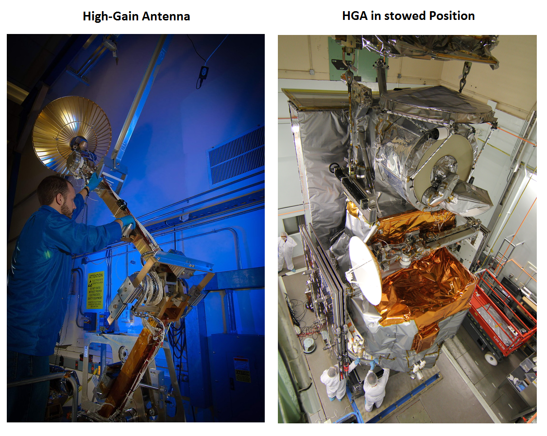
The GPM core satellite uses an S-Band communications system for data exchange with the ground. The GPM High Gain Antenna System features a deployable boom that facilitates the high gain antenna dish of the spacecraft which is installed on a two-axis gimbal mechanism to orient the antenna for communications with NASA’s Tracking and Data Relay Satellite System.
Realtime payload and housekeeping data is downlinked via the TDRSS Multi-Access Service that allows a TDRS satellite to relay data from several lower data rate users. Stored science data is downlinked via the Single-Access Service of TDRSS that uses dedicated antennas on the TDRS satellites to achieve high downlink data rates.
TDRSS data is downlinked to White Sands, New Mexico from where the GPM data is transferred to the mission operations center that then distributes the acquired instrument data for processing and publication. For realtime downlink, instrument data will be available within 15 minutes to achieve a near real-time coverage.
Command uplink is also accomplished via the high-gain antenna in nominal mission modes. GPM is equipped with omni-directional S-Band antennas that are used to communicate with ground stations. These antennas are used for telemetry downlink and command uplink and in case of spacecraft safe modes.
Attitude Determination and Control
The GPM Core spacecraft uses a suite of state of the art sensors to determine its three-dimensional attitude in space to ensure proper attitude control and Earth-pointing for instrument data acquisition. GPM incorporates star trackers and an Inertial Reference Unit as main attitude data sources.
Two wide-angle star trackers are used to acquire imagery of the sky that is analyzed by a software algorithm that compares the acquired star pattern with a catalog to precisely determine the spacecraft’s orientation in space. The star trackers are connected to the 1553 data bus to relay precise attitude data to the vehicle’s control system.
The Inertial Reference Unit used on the GPM spacecraft is a Scalable SIRU reference system provided by Northrop Grumman. The system uses gyroscopes to precisely measure changes in rotational attitude on all three axes to provide accurate attitude and rate data to the spacecraft control system. The IRU is internally redundant.
Two Medium Sun Sensors are also part of GPM’s guidance suite. These sensors have a smaller field of view than the coarse sun sensors and provide higher accuracy in their measurements. The two units have a field of view of about 17.5 degrees and measure the position of the sun with an accuracy of two degrees. MSS data is used in initial attitude hold mode and during spacecraft safe modes.
Two Magnetometer Units are installed on GPM to determine the spacecraft attitude relative to Earth’s magnetic field. Three Magnetic Torque Rods with redundant coils are used to create angular momentum by running a current through coils in the presence of Earth’s magnetic field. The torquers are regulated by computers that control the current that is passing through the coils in order to control the force generated on each axis. The magnetic torquers are used during momentum dumps.
A GPS unit aboard the GPM spacecraft determines the spacecraft position, altitude and velocity for navigation, antenna pointing and science data processing.
Attitude control is primarily provided by a Reaction Wheel Assembly. The wheels are spun by electric motors at variable speed that is changed when making attitude maneuvers. Each Reaction Wheel assembly weighs 10 kilograms and the wheels spin as fast as 6,000 rpm. The thrusters are used for periodic angular momentum desaturation – slowing down the reaction wheels and countering the resulting force with the thrusters so that the wheels can then be accelerated during standard attitude operations.
Command Handling & Data System
The GPM data system is in charge of command reception and execution, payload system operations, housekeeping operations and spacecraft control. The C&DH system uses key-components developed for the Lunar Reconnaissance Orbiter based on the VxWorks operating system for realtime operations. GPM uses a space wire, 1553 data bus and an analog RS-422 system for data transfer within the spacecraft. Housekeeping data and science data is stored in a solid-state recorder before downlink or is processed and downlinked in real time.
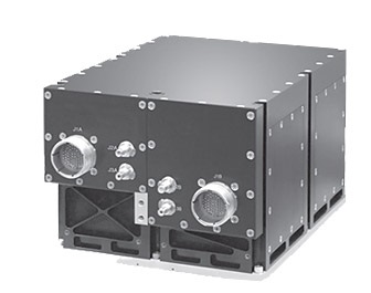
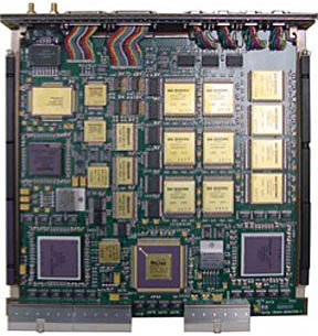
GPM is equipped with a RAD-750 Central Processing Board that is a single-card computer manufactured by BAE Systems in Manassas, Va. The processor can endure radiation doses that are a million times more extreme than what is considered fatal to humans. The RAD750 CPU itself can tolerate 200,000 to 1,000,000 rads. Also, RAD750 will not suffer more than one event requiring interventions from Earth over a 15-year period.
“The RAD750 card is designed to accommodate all those single event effects and survive them. The ultimate goal is one upset is allowed in 15 years. An upset means an intervention from Earth — one ‘blue screen of death’ in 15 years. We typically have contracts that (specify) that,” said Vic Scuderi BAE Business Manager.
RAD-750 was released in 2001 and made its first launch in 2005 aboard the Deep Impact Spacecraft. The CPU has 10.4 million transistors. The RAD750 processors operate at up to 200 megahertz, processing at 400 MIPS. The CPU has an L1 cache memory of 2 x 32KB (instruction + data) – to improve performance, multiple 1MB L2 cache modules can be implemented depending on mission requirements.
RAD750 operates at temperatures of -55°C to 125°C with a power consumption of 10 Watts. The standard RAD750 system can tolerate 100,000rads
The Mass Memory Board directly interfaces with the Telecom system of the spacecraft for data downlink and command uplink.
GPM Instruments
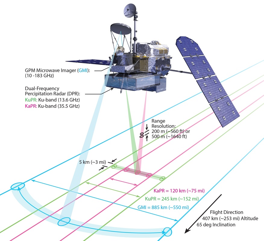
The GPM spacecraft hosts two primary instruments – the active Dual-Frequency Precipitation Radar DPR supplied by JAXA and the passive GPM Microwave Imager provided by NASA.
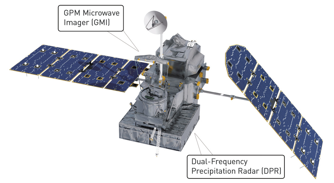
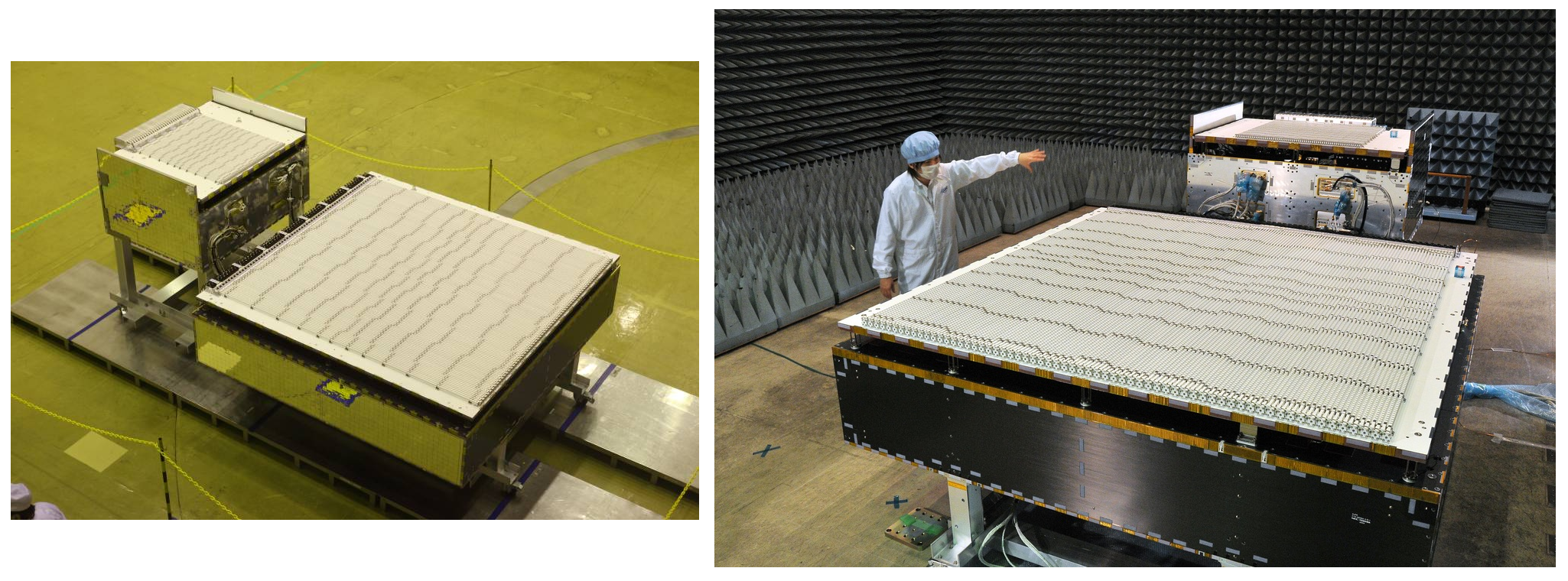
Dual-Frequency Precipitation Radar

The DPR instrument combines a Ku- and Ka-Band precipitation radar capable of making accurate rainfall measurements from the ground to 19 Kilometers in altitude. It is an upgraded system based on the successful unit flown on the TRMM mission with increased sensitivity for light rain and snowfall especially in high latitude regions. DPR data will be used to create three-dimensional observations of rain and data products such as the overall rainfall rate and Drop Size Distribution as well as mean mass diameter, particle number density and the identification of liquid, ice, and mixed-phase regions.
The instrument was designed and developed by the Japan Aerospace Exploration Agency and the National Institute of Information and Communications Technology with commercial partner NEC Toshiba.
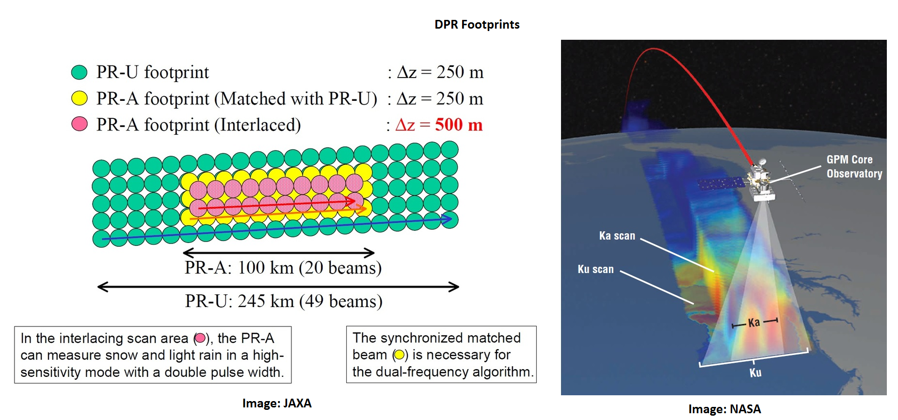
The two radars of the DPR payload are separate units known as Ku-band Precipitation Radar – KuPR operating at 13.6 Giga Hertz and the Ka-band Precipitation Radar – KaPR using the 35.55 GHz frequency. (Both radars use two slightly different frequencies to achieve two-frequency agility and double the sampling number.)
Measuring the reflectiveness of rain at these two very different radar frequencies provides information such as rain rate, cloud type and three-dimensional cloud structure, and microphysical properties like drop size. The measurement method is based on the different attenuation between the two frequencies. The KaPR is suitable for the detection of snow and light rain while the KuPR can effectively measure heavier rain. Using data from both radars and the common effective dynamic range, the payload returns drop size distribution and accurate rainfall estimates. The variable pulse repetition frequency (VPRF) technique can also be used so that DPR can realize a sensitivity of a rainfall rate of 0.2 millimeters per hour.
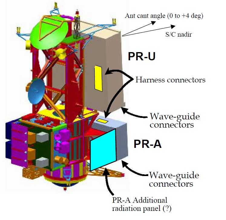
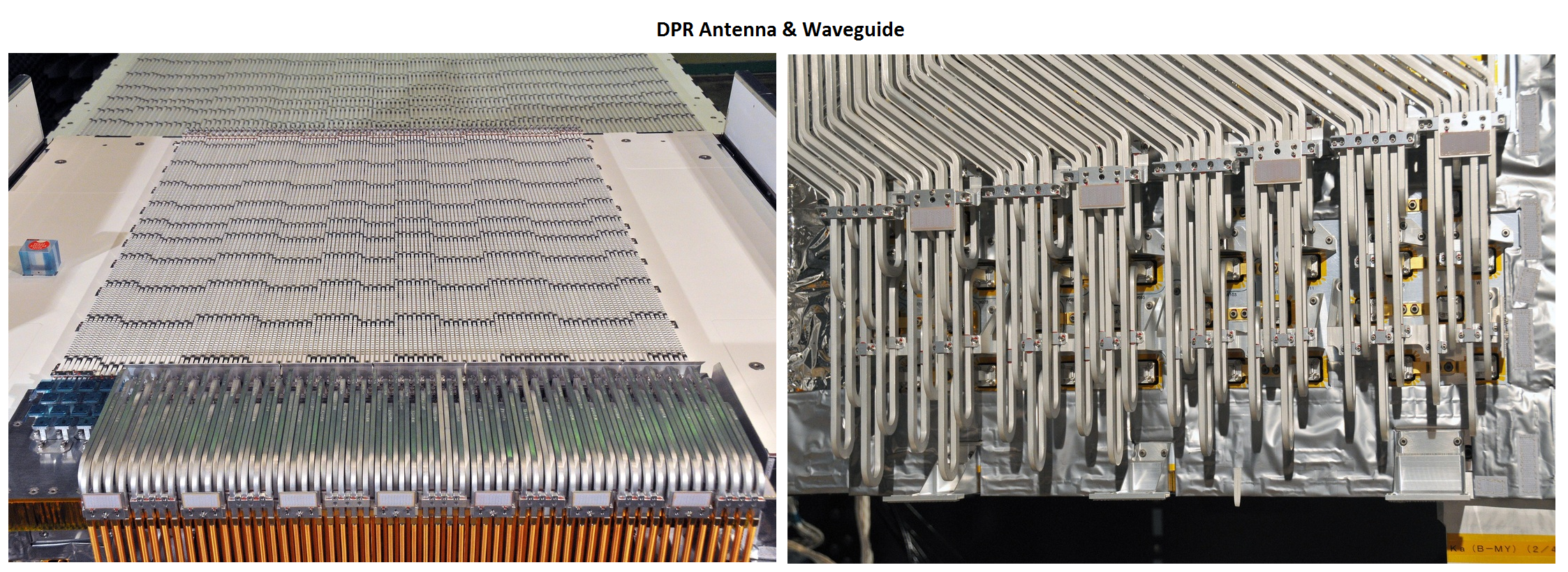
The two radars are active phased arrays – each consisting of 128 Transmit/Receive modules consisting of a transmitter, a receiver and a phase shifter. Eight T/R modules are grouped as one T/R unit for a total of 16 units per radar. The radar signal is transmitted using Solid State Power Amplifiers while the receivers are using Low Noise Amplifiers. Each radar has its own FCIF (Frequency Converter Intermediate Frequency) unit and the two share a single System Control Data Processing unit installed on KuPR.
The two phased array slotted wave guide antennas have a beam angle of 0.7 degrees and can be steered by +/-17° on KuPR and +/-8.5° on KaPR to the spacecraft nadir axis to create swath widths of 245 and 120 Kilometers, respectively. KaPR can also be operated in a high sensitivity mode featuring an interlacing scan angle which limits the swath width to 120 Kilometers but provides higher accuracy measurements of snow and light rain. In the nominal mission operation, the two antenna arrays will be aligned in order to acquire simultaneous measurements of the overlapping footprint.
Both, the KuPR and KaPR have 49 footprints, each 5.2 Kilometers wide (at nadir) – KuPR covers a 245-Kilometer swath while KaPR covers 24 footprints for a total swath of 120 Kilometers in the center of the KuPR swath. These matching footprints allow measurements with the dual-frequency algorithm. The beam matching accuracy is under 1000 meters on the ground.
In the interlaced mode, the KaPR payload adds 25 footprints by operating at double pulse widths. (KaPR can not measure light snow and rain in the outer region of the swath due to sidelobe clutter contamination.)
The KuPR and KaPR Payloads are being operated to provide temporally matching footprints with the same spatial size and scan pattern to acquire complementing data. The Pulse Repetition Frequency will vary depending on GPM’s altitude and as a function of latitude to improve measurements at higher latitudes which has been problematic in the past.
The KuPR antenna is 2.5 by 2.4 by 0.6 meters in size with a total instrument mass of about 470 Kilograms. The instrument has a peak power consumption of 446 Watts. It operates at frequencies of 13.597 and 13.603 GHz with a sensitivity of 18 dBZ – equivalent to 0.5 millimeters of rainfall per hour. One radar pulse has a width of 1.67 microseconds which creates a range resolution of 250 meters (vertical resolution). The maximum transmit power of the payload is approximately 1,014 Watts. KuPR can be operated at Pulse Repetition Frequencies of 2,900 to 4,500 Hz. A data rate of 109 kbps has been allocated for the instrument.
The KaPR payload measures 1.2 by 1.44 by 0.7 meters and has a mass of 336 Kilograms. It requires a peak power of 344 Watts. The Ka-Band payload operates at frequencies of 35.547 and 35.553 GHz having a sensitivity of 12dBZ – equivalent to 0.2mm/hour. Depending on the mode of operation, KaPR can achieve range resolutions of 250 meters (1.67 microsecond pulse width) or 500 meters (3.34 microsecond pulse width). The maximum transmit power is about 145 Watts. The payload can also operate at Pulse Repetition Frequencies of 2,900 to 4,500 Hz. KaPR has a nominal data rate of 81 kbps.
Calibration of the DPR instrument is accomplished in internal and external mode. Internal calibration includes a number of calibration sequences on the FCIF (Frequency Converter Intermediate Frequency) and the System Control Data Processing units. For the external calibration, the DPR instrument is in active operation mode and scans the signal of an Active Radar Calibrator on the ground that emits a known signature. Calibration is necessary to ensure good beam matching between the two radars which may require changes in the phase shifter to correct cross-track errors or time delay setup to fine-tune the along-track match.
In nominal science data acquisition mode, the DPR payload uses the KuPR payload that is operated along its 17-degree scanning angle while the KaPR scans along its 8.5-degree angle controlled by the KuPR System Control Data Processing unit.
The KaPR can switch from its nominal scanning mode matched with KuPR to the interlaced mode with higher sensitivity as commanded by the instrument controller when KuPR is scanning the outer region of the swath not covered by KaPR. The KaPR System Control Data Processing unit is left in standby mode for the mission to serve as redundant unit in case the primary unit of KuPR fails of the comm link between the two radars is lost.
DPR can operate in analysis and health check mode to determine the status of the amplifiers and the instrument memory. The onboard software and scanning sequences can be adjusted in flight to provide additional flexibility and respond to lessons that may be learned over the course of the mission.
GPM Microwave Imager – GMI
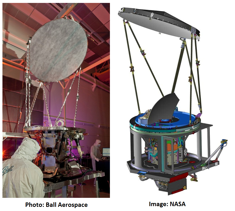
GMI is a multichannel, conical-scanning microwave radiometer serving as radiometric standard and precipitation standard thus making it a central part of the GPM constellation. The instrument provides the frequent revisit times and data quality level needed to fulfill the requirements of GPM. The instrument uses 13 channels to gather radiometric brightness data across a wide ground swath to gain insight into cloud and precipitation dynamics. GMI makes calibrated measurements at different wavelengths and polarizations.
The instrument was built by Ball Aerospace and Technologies Corporation.
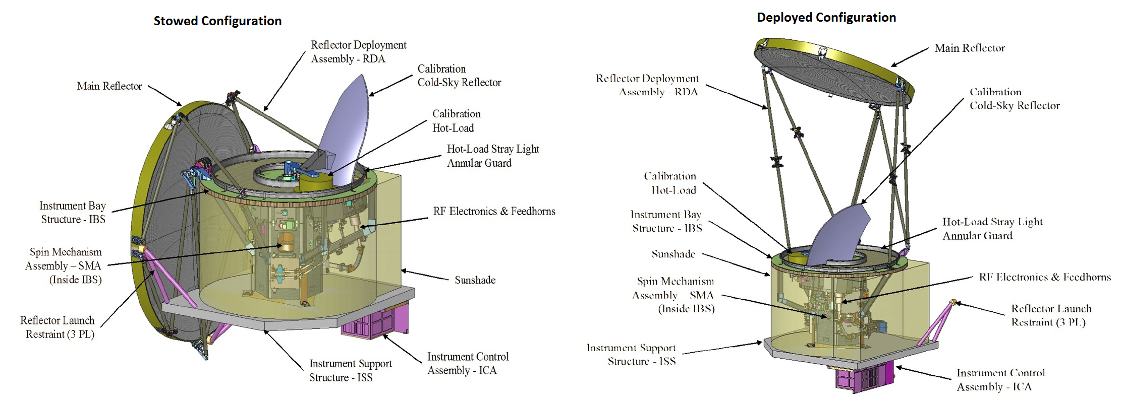
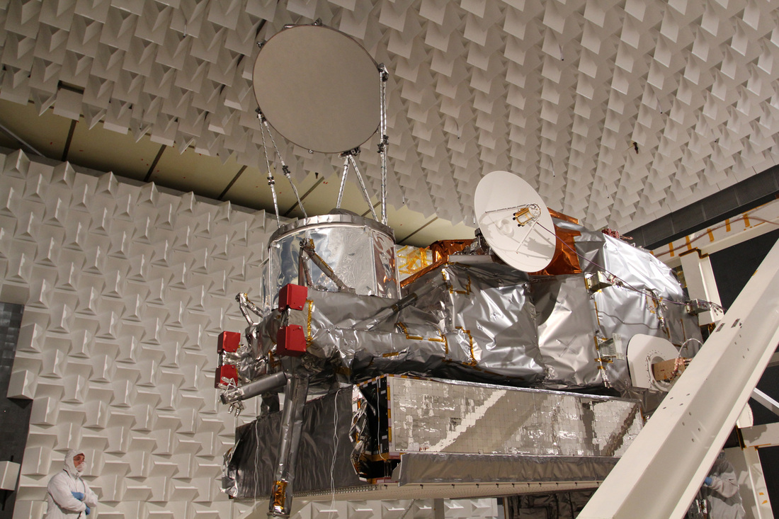
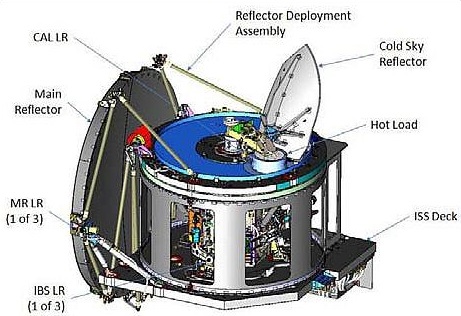
GMI consists of a large rotating main reflector and an Instrument Support Structure facilitating the RF electronics and sensors as well as the spin mechanism and support systems. In its deployed configuration, the instrument is 1.4 by 1.5 by 3.5 meters in dimensions. GMI weighs about 166 Kilograms.
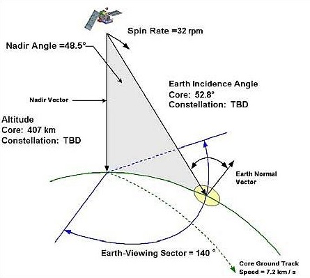
GMI uses a conical scan geometry. The off-nadir angle that defines the cone swept out by the imager is 48.5 degrees which creates an Earth Incidence Angle of 52.8 degrees – identical to that of previous missions like TRMM. This geometry means that GMI scans an area in front of the spacecraft.
The parabolic reflector rotates along the vertical axis of the GMI instrument at 32 revolutions per minute. The 1.22-meter diameter reflector weighs about 12 Kilograms. It scans an Earth-viewing sector of 140 degrees centered on the velocity vector of the GPM spacecraft. The remaining 260 degrees of each revolution are used for calibrations and housekeeping operations. The 140-degree sector corresponds to a swath width of approximately 885 Kilometers.
The GMI swath overlaps that of the DPR instrument with very little temporal difference (GMI images the area first before the nadir-mounted DPR sees the region).
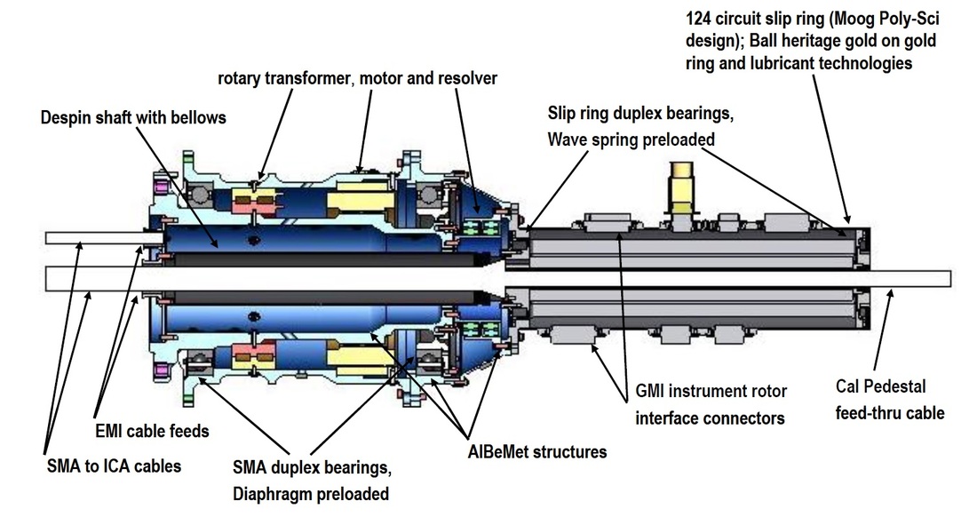
The GMI Spin Mechanism Assembly (SMA) is required to maintain a constant spin rate of the instrument of 32 rpm for the three-year mission plus the duration of any mission extensions. The system provides a spin accuracy of 0.1% using a pair of angular contact bearings, separated axially on a shaft driven by a 3-phase direct current torque motor with a 2-speed resolver for communication and position feedback. The high-precision electro-optical bearing hosts a power and data transfer drive. It is based on the BATC system employed on the WindSat spacecraft that has been operating for about a decade in orbit. Some changes to the design were made to optimize the SMA for GMI and implement lessons learned on previous missions.
The instrument has its own momentum compensation. The control hardware and software that control instrument spinning and momentum compensation reside within the instrument controller assembly. This assembly consists of the controller itself and a momentum wheel for momentum compensation, installed under the structure supporting the GMI sensor.
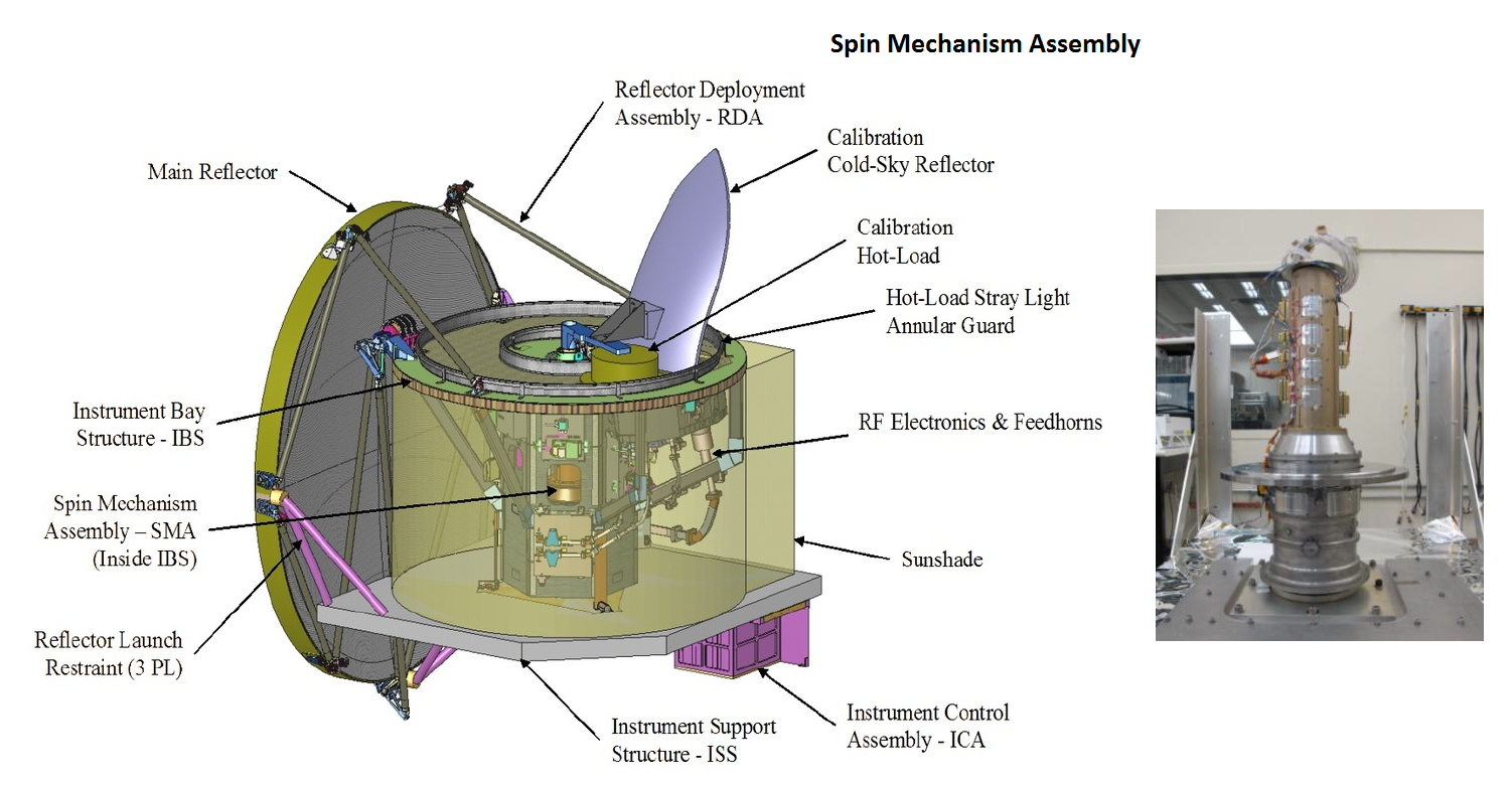
The GMI instrument body consists of the Instrument Support Structure which is a composite panel that interfaces with the spacecraft structure and supports the instrument. The Instrument Bay Assembly is a hexagonal structure with a circular top deck facilitating the Spin Mechanism Assembly, RF electronics, instrument control equipment, the Reflector Deployment Assembly and other system such as the Calibration Substructure.
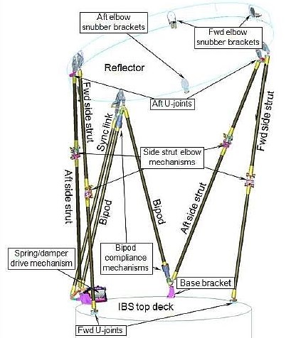
GMI’s main reflector is deployed and supported by the Reflector Deployment Assembly. It consists of an aft bipod structure and forward and aft strut assemblies that connect to three locations on the reflector and four locations on the upper instrument deck.
The struts consist of graphite epoxy composite tubes bonded to titanium fittings that attach to a number of joints to allow the RDA to be folded up for launch. The reflector is launched in a stowed position secured to the GMI main structure using restraints that deploy after orbital insertion. The Reflector Deployment Assembly then has to move the main reflector to a position within 0.5 millimeters of that used in ground testing and maintain that position throughout the mission.
The force to initiate the deployment is provided by a torsion spring on the aft bipod that has a fluid dampener for speed control. Binding of the strut joints is avoided by the use of spherical and revolute hinge joints creating an under- constrained structure. A synchronization linkage that directs the motion of the reflector ensures good control of the deployment sequence. The spring loads lock out in their deployed configuration which will end the deployment of the reflector taking a total of under five minutes.
There are a six Launch Restraints – three on the Instrument Bay Assembly and three on the main reflector, acting as load bypass mechanism for the SMA bearings and a load transfer system from the instrument to the spacecraft. In the deployed configuration, the LR transfer loads for the rotation of the reflector are passed along through the restraints. Over the course of the mission, the RDA has to maintain the reflector position to within 0.25 millimeters.
The Spin Motor Assembly uses several static elements to support instrument equipment. Mounted on bellows couple the slip ring of the SMA to a Despin Assembly, the de-spun equipment does not rotate with the rest of the instrument.
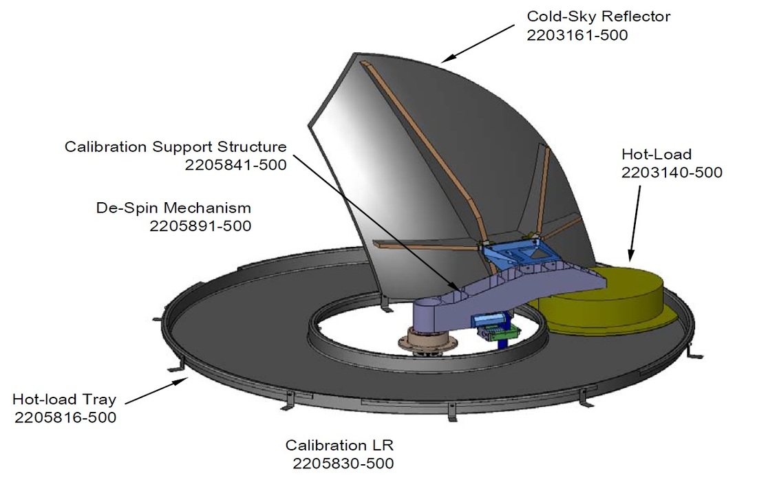
Two calibration targets are installed on the top the of the instruments that are being scanned as part of the 260-degree calibration cycle of each instrument rotation. Calibration is accomplished using a cold sky target and a precisely controlled hot load. The cold sky target is a reflector targeted at space to provide the coldest possible target for calibration purposes. The sky reflector has been sized to provide a high beam efficiency to cold space.
The hot load uses a design that minimizes thermal gradients to provide a high stability. It is equipped with a shroud that limits exposure of the target to solar radiation and other external influences. 14 thermistors are used to precisely measure the current state of the hot load at each scan with special focus on possible spatial and temporal variations even on small scales.
In addition to the two calibration targets, GMI uses internal noise diodes that introduce a known disturbance that will be analyzed to track the non-linearity of the receivers over the course of the instrument lifetime and also act as a cross-calibration device to verify the short-term stability of the hot load and cold sky calibration methods by means of a four-point calibration method – measuring the sky target alone, the hot load alone, the sky target with noise diodes active, and the hot load with noise diodes active. This method provides a more accurate instrument calibration using a polynomial fit to the instrument response.
GMI uses a total of 13 microwave channels (see table) with a frequency range of 10 to 183 GHz. The RF feedhorns are located within the Instrument Bay as part of the antenna subsystem and receiver electronics that rotate at 32 rpm. The system is protected by a sunshade and thermal shroud with a stationary opening to cold space. GMI has a 1.22-meter aperture which provides excellent spatial resolutions for channels one through five.
For these channels, the aperture is used in beam formation, offering fine spatial resolution compared to other radiometers employed on previous missions.
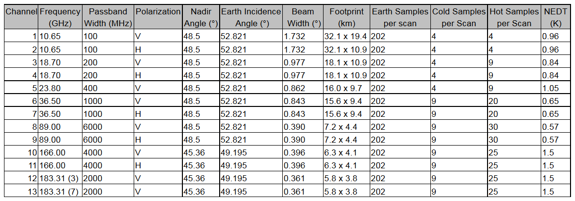
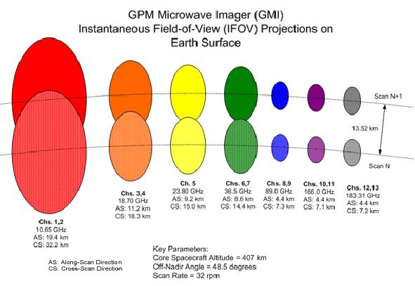
The frequencies covered by GMI enable the instrument to optimally retrieve data on heavy, moderate and light precipitation using the polarization difference at each channel as indicator for the optical thickness and water content. The 10GHz channels at vertical and horizontal polarization with a noise equivalent delta temperature of 0.96 are used to measure the heavy precipitation occurring in the tropics. The 9 and 37 GHz channels are dedicated to measuring moderate and light precipitation primarily over the Oceans. The 24GHz channel provides correction to the absorption by water vapor in other channels. Measurements at the 89 GHz frequency yield data on large ice particles in clouds to examine stratiform precipitation over ocean and heavy precipitation over land masses. The two 166 GHz channels are used to measure light precipitation while the two 183 GHz (+/-3 and +/-7 GHz) channels are sounding channels for the detection of scattering signals from small ice particles and water vapor close to the surface to better measure precipitation over snow-covered land.
The footprint sizes vary with the frequency of the individual channels (see table). The lower frequencies have large footprints that have sufficient overlap in the along-scan direction to achieve a continuous and complete coverage. Channels 8 through 13 no longer have overlap from one scan to the next causing gaps in coverage, however, the minimum coverage requirement is maintained with the IFOVs of these channels. To satisfy the Nyquist criterion, all channels are being sampled at a minimum of two times as the GMI scans a single IFOV. To guarantee satisfactory co-registration, the sample times for each channel are being set as integral multiples of each other.
GMI serves as a transfer standard for the other radiometers deployed in the GPM constellation. Using GMI data as a reference for other radiometers, the brightness temperature calibration will be adjusted to achieve a common basis across the complete constellation to reduce precipitation retrieval differences due to calibration biases. Inter-calibration is an important factor to ensure the high-standard of science data that is expected from GPM.
Ground Segment
The GPM constellation has the objective of providing global precipitation data in near-real time requiring a ground segment that supports quick data processing and publishing.
The Mission Operations Center at NASA Goddard receives the downlinked data from the spacecraft via the White Sands TDRSS downlink site and is in charge of telemetry monitoring to assess spacecraft health, develop commands and observation sequences for uplink, plan mission operations such as orbital maneuvers and spacecraft housekeeping. The TDRSS and GPM teams are also in a constant exchange of their respective orbital vectors to plan real time communications via multi-access service and stored comm sessions via single-access service. The Software Development and Validation team receives the commands developed by the Mission Operations Center to verify them using the spacecraft simulator; the team also provides refined flight software versions as requested.
The Mission Operations Center interfaces with the Precipitation Processing System – science and telemetry data is delivered as 5-minute science data files and spacecraft telemetry files. In turn, the PPS interfaces with MOC to provide activity requests for the instruments from Goddard (GMI) and JAXA (DPR).
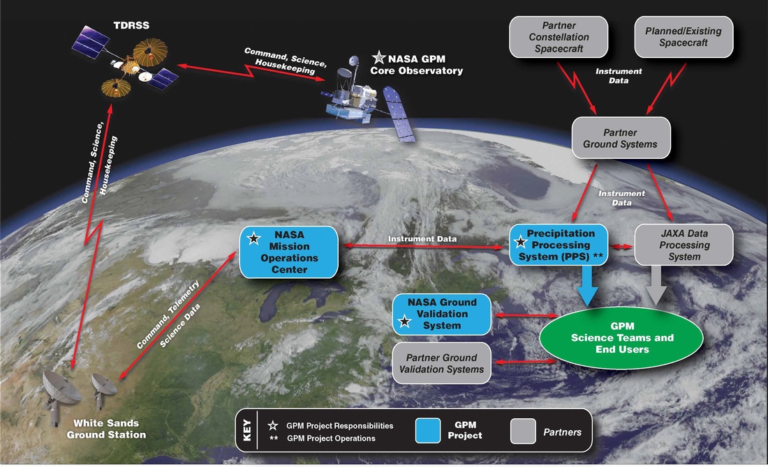
The Precipitation Processing System creates the science products from the science data and metadata files received from the spacecraft. These high-level data products are then delivered to the user community.
GPM mission operations are highly automated and the Ops Center is only staffed eight hours a day, five days per week. The spacecraft requires very little commanding as the instruments will be in constant survey mode for the majority of the mission and communications via TDRSS are primarily done in real-time.
Planning that is required for GPM core includes special science activities, instrument calibrations and orbital maneuvers to maintain the operational science orbit.
Data Validation
The methods and algorithms for precipitation measurement by GPM have been and are being validated through a number of different activities including studies of precipitation measurements and in-flight validations through a number of data sources.
Prior to the mission, a number of field studies was performed to validate the physics of precipitation to ensure the mechanisms occurring in reality match up with the models and algorithms used on GPM. These activities focus on the extensive collection of targeted airborne and ground-based measurements of precipitation processes to refine satellite retrieval algorithms using model-simulated and observation-derived microphysical databases. The aim of those activities is a better understanding of the physical relationship between clouds/precipitating particles and the microwave radiances at different frequencies to optimize the GPM retrieval algorithm. Additionally, ground based and airborne observations may uncover discrepancies as a result of different retrievals which would prompt further study.
Field studies were carried out to look at the mechanism of precipitation in certain situations such as light rain in shallow melting layers, precipitation from continental convective clouds, snowfall at high latitudes, and microphysics and processes associated with cold season precipitation to improve the snowfall algorithm.
Two ground sites are involved in an extensive validation campaign for GPM – the C-band polarimetric Radar, Nago and the 400-MHz Wind Profiler, Ogimi both located in Japan. These two radar sites make measurements of atmospheric turbulence echo and precipitation echo. From this data, properties such as drop size distribution can be determined taking into account effects of wind speed, the intensity of atmospheric turbulence, and background winds. Data from the sites leads to accurate estimates of the specific attenuation (k) and the radar reflectivity (Z) for Ku-band which can serve as a direct validation of DPR data.
In addition, GPM uses numerous ground based sensors to make precipitation measurements which can be compared to the space-based measurements to verify data accuracy.
Mission & Orbit Design
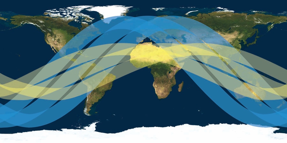
Launching atop an H-IIA 202 rocket blasting off from the Tanegashima Space Center, Japan, GPM is targeting a circular orbit at an altitude of 407 Kilometers at an inclination of 65 degrees.
This orbit was chosen because of the specific scientific goals of the mission, ensuring sufficient overlap with other constellation spacecraft for cross-calibration and covering a large portion of Earth’s surface for data acquisition with minimal ground track repeating. The chosen orbit allows an optimal instrument coverage with minimal time to achieve global coverage.
To achieve its scientific goals, GPM has to maintain is orbit in the high-drag environment at 407 Kilometers requiring a great deal of planning to minimize the impact of orbit maintenance on science activities and to enable long-term orbit predictions.
A Frozen Orbit design selects a specific mean eccentricity and argument of perigee to ‘freeze’ the line of apsides motion – minimizing the natural drifts due to earth’s potential perturbations. This provides a minimal altitude variation over a given latitude which is of great interest to scientists in order to produce accurate and repeatable precipitation data. A frozen orbit can be achieved by setting the argument of perigee to 90° or 270° or placing the spacecraft at a critical inclination of 63.5° or 116.5°. In a frozen orbit, the careful selection of the initial conditions lead to a predictable eccentricity evolution and a minimal predictable altitude variation with latitude over the course of an extended amount of time.
One of the drivers of the GPM orbit maintenance design was the desire of a minimal variation over a given latitude coupled with a minimal amplitude of the altitude over a single orbit.
With GPM in an orbit close to the critical inclination of frozen orbits, the eccentricity can be freely chosen to achieve an orbit with minimal altitude variations. Naturally, GPM is targeting an eccentricity very close to zero that will be maintained by keeping the orbit circular through propulsive maneuvers. (e=0.0001 +/- 0.00005)
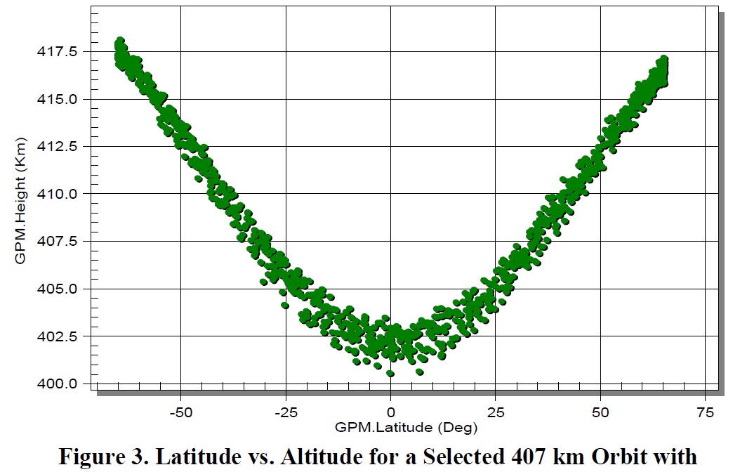

GPM Core has been assigned a reference altitude of 407 Kilometers and a box of 0.5km or 1km (depending on the mission phase). These values specify the maximum deviation from the reference altitude.
Using propulsive maneuvers to keep the orbit within 1 Kilometer to the reference orbit, the variation of the altitude over any given location is constrained to approximately 3 Kilometers while the overall variation of the altitude from 0 to 65 degrees does not exceed 18 Kilometers over an extended period of time. The argument of perigee is not controlled actively.
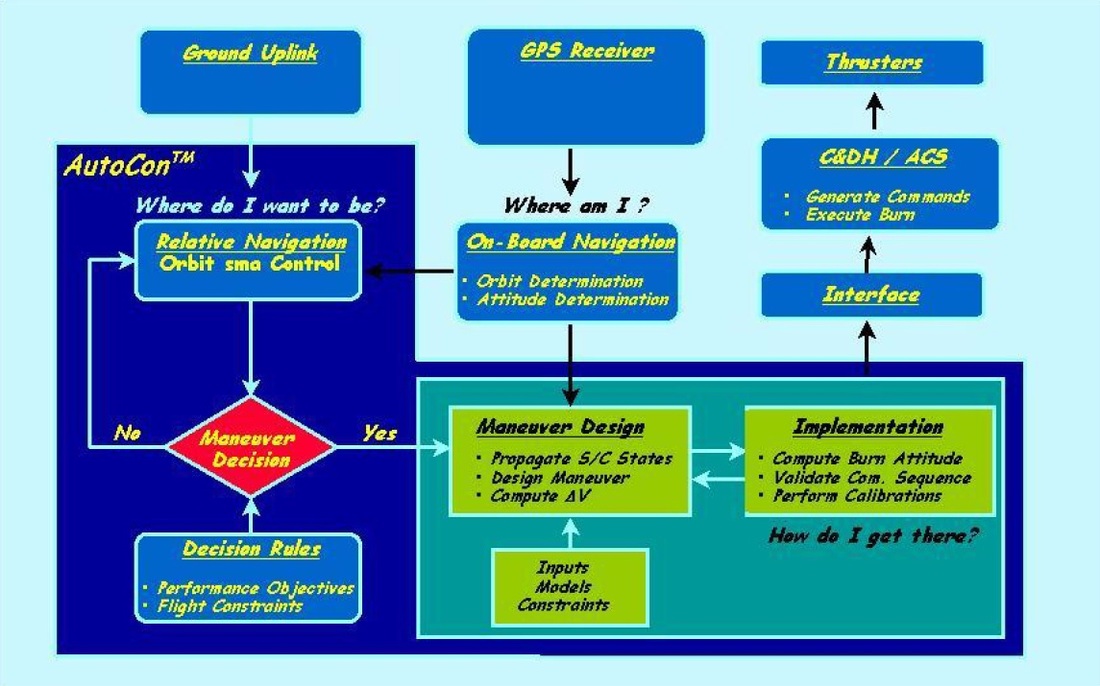
Maintaining this orbit requires some effort in the form of frequent analysis and optimal maneuver integration as the orbit experiences changes due to predictable Earth perturbations and unpredictable space weather events such as solar and atmospheric drag. GPM uses the AutoCon system that will autonomously analyze the orbit, plan and target maneuvers, notify ground control of the impending maneuver for manual intervention, and develop commands for the maneuver execution.
For that, AutoCon uses GPS data for orbit determination and maneuver planning. The orbit will be computed several times a day and AutoCon will autonomously target propulsive maneuvers with a defined lead time to allow intervention by teams on the ground. AutoCon is capable of targeting burns in compliance with operational requirements such as shadow, sun angle, spacecraft attitude and timing requirements. The algorithm is programmed to target the precise reference orbit of 407 Kilometers and minimize the eccentricity.
A number of safeguards within the AutoCon software and the GPM control system and attitude control system software prevent erroneous burns of long duration – the final barrier is the ACS controller that limits all burns to a duration to 70 seconds.
In the nominal mission, orbit maintenance burns can occur as frequently as every three days in periods of high solar activity, but on average, maneuvers will be performed every ten to 12 days with AutoCon giving 24 or 48-hours prior notice. The burns will usually have a delta-v (change in velocity) on the order of 0.55m/s. Using the four dV jets in conjunction with the ACS during burns causes a propellant consumption of 1.9kg/maneuver at the start of the mission and 1.4kg/maneuver at the end of the mission due to the propulsion system being operated in blowdown mode. Burn times will increase from 35 seconds to 70 seconds over the course of the mission.
At the end of the mission, GPM Core will make an untargeted destructive re-entry. The mission complies with all regulations on space debris and risk mitigation associated with components surviving re-entry and extensive study was carried out looking at the high-risk components installed on the vehicle.
Launch
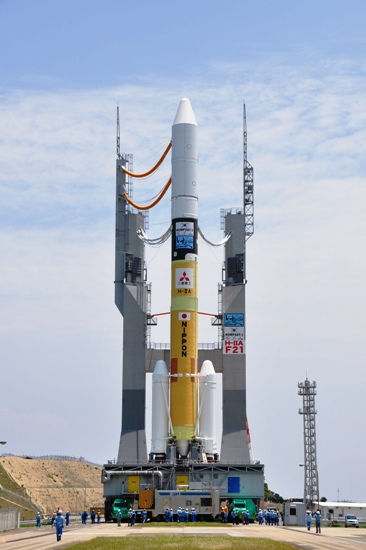
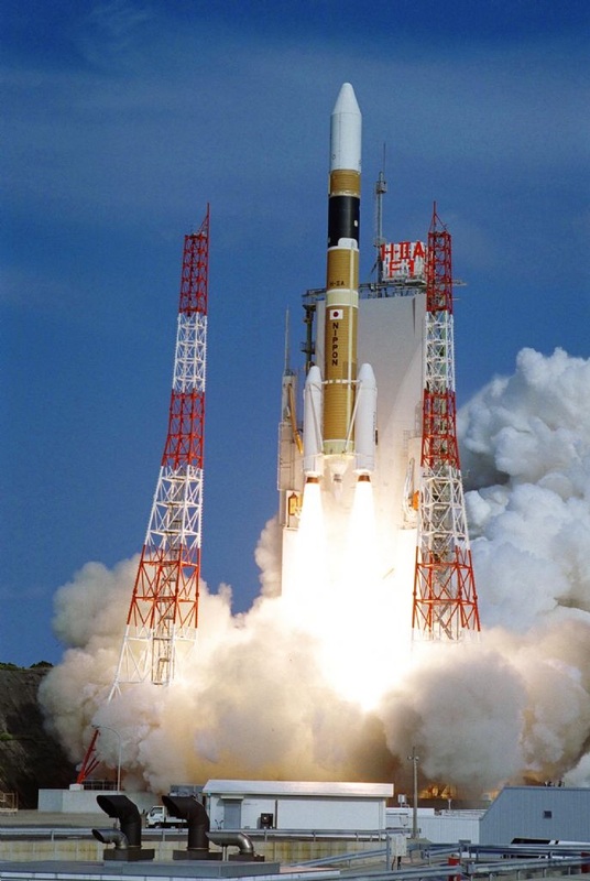
The GPM Core Mission is being launched atop a Japanese H-IIA 202 rocket provided by Mitsubishi Heavy Industries. H-IIA has a liftoff weight of 285,000 Kilograms standing 53 meters tall with a core diameter of 4 meters using a two-stage stack with two Solid Rocket Boosters attached to the first stage. The rocket is capable of delivering payloads of up to 11,000 Kilograms into Low Earth Orbit.
The first stage of the H-IIA is 37.2 meters long and capable of holding about 100,000 Kilograms of cryogenic propellants, Liquid Oxygen and Liquid Hydrogen for consumption by the single LE-7A main engine. LE-7A is a staged combustion cycle engine delivering 1,087 Kilonewtons of thrust. Attached to the first stage are two SRB-A Solid Rocket Boosters – each 15.1 meters long and 2.5 meters in diameter weighing 77 metric tons. Each of the boosters burn 65,040kg of propellants during a 100-second burn. SRB-A delivers 2,260kN of thrust. Booster separation is triggered by pyrotechnics and the SRBs use struts to ensure a clean separation.
The second stage of the H-IIA 202 is 9.2 meters long with a diameter of 4 meters. It also uses LOX and LH2 propellants, being filled with 16,600kg of cryogenics. One LE-5B engine powers the second stage providing a vacuum thrust of 137kN. The engine can make multiple ignitions to target a variety of orbits. A 4.07-meter fairing tops the stack and protects the GPM Core Satellite for launch.
The Launch Countdown operation for H-IIA begins about 12 hours before launch with the rollout of the launcher from its final assembly building. The trip from its assembly building to the sea-side launch pad – located at the South-Eastern tip of Tanegashima Island – South of Kyushu, the southernmost of Japan’s main islands takes about 30 minutes.
After arriving at the Pad, technicians connect data and electrical lines and put propellant umbilicals in place before completing final fueling preparations and close-outs. About eight hours before launch, teams evacuate the launch pad to get ready for the long propellant loading sequence.
Beginning at about X-7 Hours and 45 Minutes, the complex propellant loading sequence gets underway with the pressurization and chilldown of ground support systems handling the -183-degree Celsius LOX and -253°C LH2. Fueling goes through a number of steps including ground support system chilldown, propellant tank chilldown and propellant loading, before tanking enters replenish mode. The propellant loading sequence takes approximately three hours until the 116,600 Kilograms of cryogenics needed for launch are loaded. Replenishing the propellants as they boil off, the tanks are kept at topping level until late in the countdown.
The majority of the countdown will be spent with extensive tests of the launch vehicle’s flight control system, checks of all electronics and controllers and verifications of the radio link between the launcher and the ground. Flight Termination System testing is also performed in the early stages of the countdown.
At X-60 Minutes (instead of T- or L-, the H-II Countdown Clocks use X- Time), the Terminal Countdown Sequence will start. During the final hour of the countdown, last-minute items will be closed out and the vehicle will be reconfigured for the Automatic Countdown Sequence starting just 4.5 minutes prior to blastoff.
As computers are given control of the countdown, H-IIA’s Propellant Tanks will be pressurized for flight. At X-3 minutes the launch vehicle is switched to internal power while GPM will have been switched to battery power ahead of the final countdown sequence. One minute before liftoff, thousands of Kilograms of water are being poured over the launch platform to suppress the acoustic loads at ignition & liftoff. Launch Vehicle Ordnances will be armed at X-30 Seconds and the Guidance System of the Vehicle is being switched to Flight Mode 12 Seconds later before the Sparklers underneath the LE-7A main engine ignite to burn off residual Hydrogen.
Ignition Sequence Start is commanded at X-5.2 Seconds and the LE-7A Engine soars to life as the turbopumps spin up to flight speed being monitored by on-board computers to make sure the engine is healthy before the booster ignition command is issued at T-0 – committing the vehicle to launch.
As the boosters ignite, H-IIA will jump off its pad with a total thrust of 570,840 Kilograms. The twin boosters deliver 81% of the total liftoff thrust of the launcher that will make a short vertical ascent before executing its roll and pitch program to achieve the planned ascent trajectory – flying south to depart Tanegashima Island. On its way uphill, H-IIA quickly passes Mach 1 and Maximum Dynamic Pressure.
The two boosters burn until T+1 minute and 39 seconds – burnout will be sensed by the declining pressure in the combustion cambers. Booster jettison occurs at T+1:48 as both SRBs separate simultaneously after completing their job of helping accelerate the vehicle to 1.5 Kilometers per second. Booster separation is performed at an altitude of 47 Kilometers.
Powered flight continues on the LE-7A engine of the first stage alone. The engine delivers 109,300 Kilograms of thrust, burning about 260 Kilograms of cryogenics per second.
Once reaching an altitude of 148 Kilometers, the launcher will jettison its protective payload fairing to expose the GPM satellite on its way uphill. At that altitude, the stack has left the dense portion of the atmosphere and the satellite can no longer be harmed by aerodynamic friction and other forces.
Six minutes and 36 seconds into the flight, the first stage will shut down its engine. At that point, the stack will be at an altitude of 230 Kilometers traveling 5.0 Kilometers per second. Stage separation occurs eight seconds after MECO and the second stage will prepare for its ignition.
The single LE-5B engine will ignite at T+6 minutes and 50 seconds, reaching its full thrust of 13,970 Kilograms for an eight-minute and eight-second burn to insert the stack into its target orbit, providing a delta-v of 2.7km/s. Following shutdown of the LE-5B at T+14:58, the second stage will use its attitude control system to re-orient for spacecraft separation.
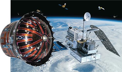
GPM will be sent on its way at T+15 minutes and 49 seconds. The second stage will then continue its mission to deploy the secondary payloads and perform disposal maneuvers. (Detailed Overviews of all seven secondary payloads)
For GPM, the moment of separation marks the start of a pre-programmed sequence that includes several steps. The GPM Core satellite will establish a stable three-axis orientation in attitude safe mode and acquire communications with ground stations. Solar array deployment occurs shortly after insertion and the confirmation of GPM being power-positive will mark the completion of a successful orbital insertion. Over the first hours and days, the spacecraft completes a series of health checks to make sure it made it into orbit in good shape. Afterwards, mission operations will transition to commissioning to test the two instruments and prepare for mission operations that get underway several weeks after launch.
