Gaia Instrument Information
The Gaia Spacecraft carries a payload of three instruments to complete its star-mapping mission:
- The Astrometric Instrument determines the positions of stars in the sky and provides data to track their motion and parallax
- The Radial Velocity Spectrometer determines the velocity of a star along the line of sight of Gaia using doppler shift measurements in a high-resolution spectrum
- The Photometric Instrument creates two low-resolution spectra in the red and blue range to reveal temperature, mass and chemical composition of stars
Scanning Law Overview
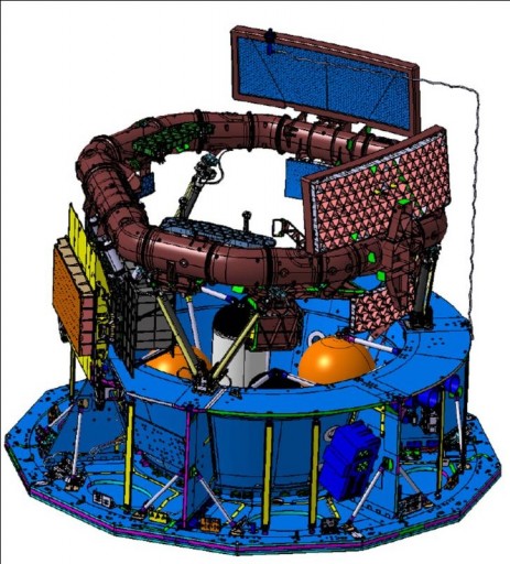
Although Gaia theoretically carries three instruments that complete three separate tasks, the entire payload has to be seen as a single integrated assembly as most equipment is shared by the three instruments.
Gaia’s science payload consists of two telescopes that are mounted on the hexagonal optical bench and share common focal plane equipment. The two telescopes are looking through two apertures on the Thermal Tent. The viewing directions are 1.7 by 0.6 degrees in size and are separated by a highly stable basic angle of 106.5 degrees.
Global astrometry requires the simultaneous observation of two fields of view in which the star positions are measured and constantly correlated. The angular distance between the two fields of view is referred to as the basic angle, 106.5 degrees in Gaia’s case. The scanning law developed for Gaia requires the satellite to be spinning perpendicular to the two lines of sight so that the two lines of sight describe a ‘great cycle’ within a single spin period.
Gaia operates at a spin rate of 4 revolutions per day. Due to the spinning, the instruments see the stars crossing each field of view in a regular motion. To achieve an all-sky survey, the satellite is put through a slow precession on the Satellite-Sun-Axis which produces a continuous drift of the great circle on the sky. The constant solar angle for Gaia is 45 degrees.
A fundamental aspect of astrometric measurements is the repetition of measurements – covering the entire celestial sphere a large number of times over an extended period of time.
At a precession cycle of about 63 days, Gaia will map each star 70 times on average during its primary mission. For all these observations, the basic angle between the two fields of view has to be constant.
To gain astrometric data (two angular positions & corresponding proper motions as well as parallax), the relative separations of thousands of stars are cataloged and the repeated measurements of each star build a network in which the star is connected to a wealth of others in every direction. Data processing on the ground derives the actual star parameters via sphere reduction.
Radial Velocity is determined by the Radial Velocity Spectrometer using doppler shift technique.
Telescope Design
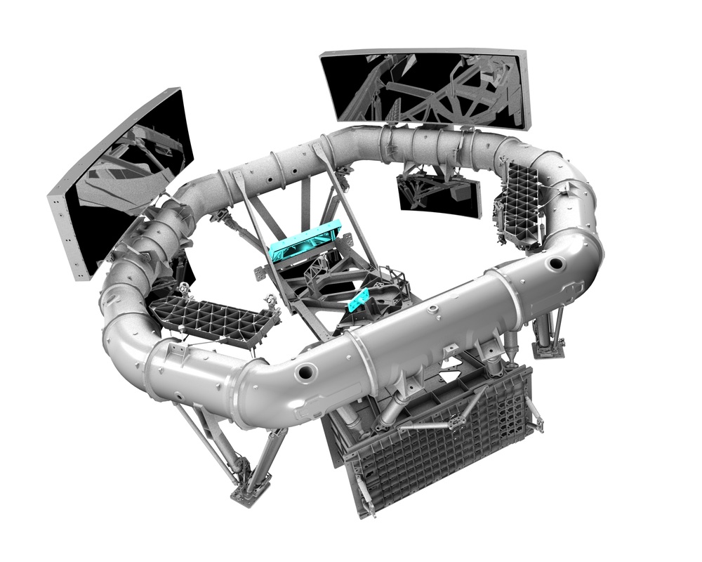
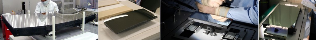
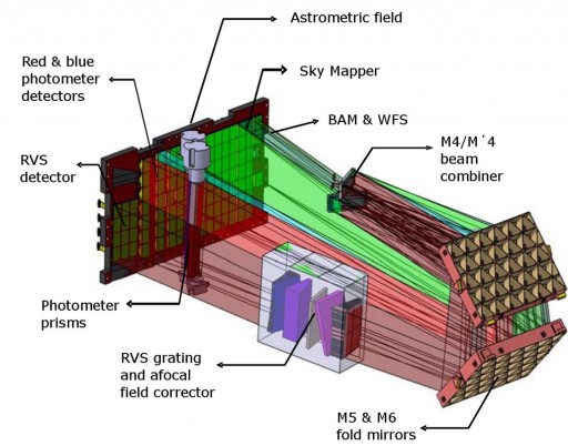
The two telescopes of Gaia’s instruments are identical in construction sharing an optical bench and common focal plane assembly. Light passes through the apertures and onto the two primary mirrors opposite to the respective aperture (designated M1 and M’1). The primary mirrors are 1.45 by 0.5 meters in size. Like all the other mirrors, the primary mirrors are rectangular in shape and have been fabricated from blanks made of sintered silicon carbide – the same material used for the optics bench, chosen because of its favorable thermal properties.
The mirrors were shaped using computer-guided milling and polishing machines. The mirror blanks were coated with a layer of silicon carbide via vapor deposition. Each mirror was polished to an accuracy of 10 nanometers. Following polishing, the mirrors were coated with enhanced silver reflective coating.
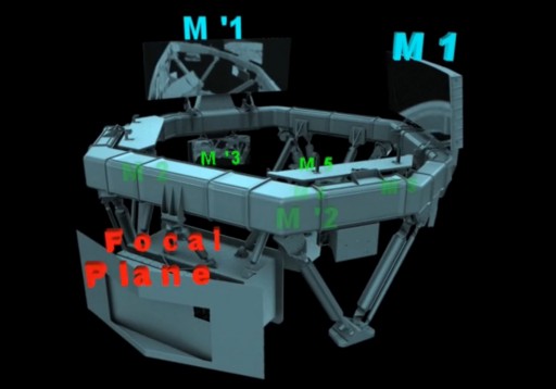
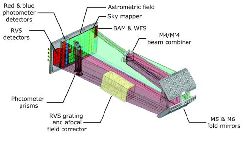
After being reflected by the primary mirrors, the light is bounced back and forth between the M2 and M3 mirrors to create a total focal length of 35 meters. M2 and M3 are 0.65 by 0.275 meters in size. The M4/M’4 mirror acts as a combiner that reflects the light onto the focal plane assembly via the M5 and M6 fold mirrors that are 0.54 by 0.36m in dimensions.
Combining the light means that the two images coming from the two viewing directions are superimposed onto one another and detected simultaneously.
Telescope Mirrors (M1, M2/3, M4 & M5)
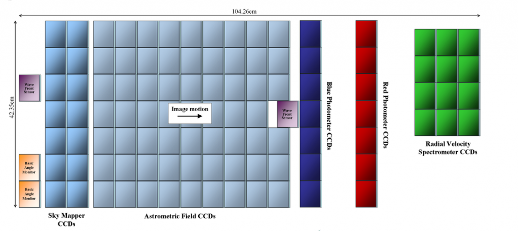
Focal Plane Assembly
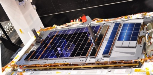
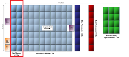
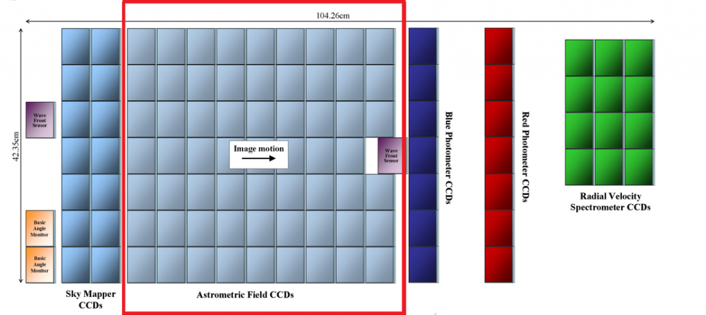
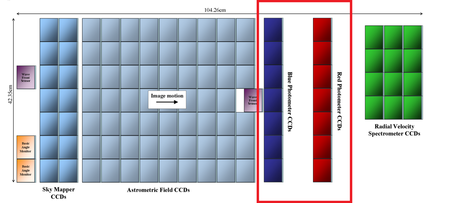
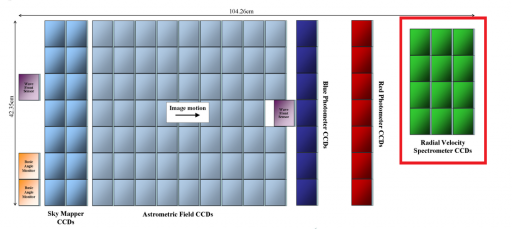
The focal plane is divided into different portions that correspond to the different instruments.
The Gaia Focal Plane Assembly is 104.26 by 42.35 centimeters in size featuring a total of 106 Charge- Coupled Devices that are used as detectors. Each CCD is 4500 by 1996 pixels in size with pixels that are 10 micrometers by 30 micrometers in size. The CCDs are arranged in 7 rows and 17 columns.
Because the Gaia spacecraft slowly spins perpendicular to the viewing direction, the image moves across the focal plane as the spacecraft spins – meaning that each star passes along a row of CCDs allowing the individual instrument CCDs to be grouped in columns in order to have each instrument detect each of the detectable stars within the field of view.
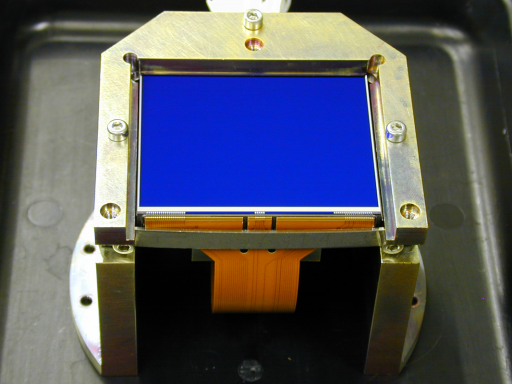
CCD Overview & Integration Technique
The CCDs on the focal plane are operated in a Time-Delayed Integration Mode. The fixed TDI period of the CCDs is constantly synchronized with the measured spin rate of the vehicle because the speed at which the object moves across the focal plane depends on the actual spin rate of the observatory.
At the nominal spin rate, each object passes a line within the CCD in 982.8 microseconds which corresponds to the TDI Time. The nominal integration time per CCD is 4.42 seconds, corresponding to 4500 pixels along scan [4500×982.8μs=4.42s]. This Time-Delayed Integration is used to precisely match the motion of the optical image to the electronic image that is created.
To avoid pixel saturation for bright objects, electronic TDI gates are activated to reduce the integration time for particular windows. The TDI gates lower the effective number of pixels along the scan direction. There are 12 TDI gates that operate to optimize the signal for bright stars at the minimum expense for faint stars. To avoid extensive TDI gate use, the CCDs have a high full-well capacity of >190,000 electrons.
Also, the CCDs which are large area, full frame, back illuminated devices, feature a supplementary buried channel (SBC) to deal with the radiation environment of space. Shielding will reduce the ionizing radiation dose to 5krad, but non-ionizing dose is expected to be high. The cross section interaction between electrons and traps is reduced by the SBC.
The CCDs also employ anti-blooming features and use 4-phase electrode structure in the image section and 2-phase structure in the read-out register leading to a two-staged buffered output mode. Dark current effects are being mitigated by operating the CCDs at a low temperature of –115°C.
Sky Mapper & Window Assignment
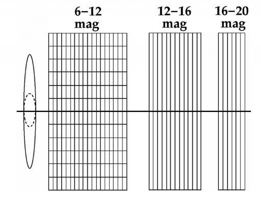
As light from a particular star enters the instrument, it first enters the Sky Mapper portion of the focal plane assembly. These are two columns of CCDs – every object brighter than 20mag crossing the focal plane is either registered by SM1 or SM2 to differentiate between objects being observed via Telescope 1 and Telescope 2. This is achieved by a physical mask that is installed in each telescope’s intermediate image to block out either SM1 or SM2. The objects that are registered by the Sky Mapper are then tracked as they cross the focal plane to be able to tell the two images from the two telescopes apart.
The Sky Mapper assigns a “window” to each object to limit the amount of CCD pixels that have to be read-out subsequently to reduce noise and reduce the total amount of data that has to be downlinked. The size of the window has been chosen to create optimal results from all three instruments taking into account the resolution of star images, the smearing in the across scan direction, the scientific interest in double stars and the sky background that has to be known for subtraction. Window sizes vary with brightness of a star and window sizes are optimized for the purpose of each CCD column.
The M6 mirror reflects the light directly onto the Sky Mapper CCD columns and the Astrometric Detector that follows in the +y direction.
Astrometric Instrument
After passing the Sky Mapper, the objects are detected by a total of 62 Astrometric CCDs that occupy nine CCD columns. The first CCD column is used to verify that the Sky Mapper registered actual objects in order to filter out false readings that could be caused by cosmic rays. The objects then progressively cross the next eight AF columns.
The astrometric instrument returns data that allows scientists to measure the image centroids in order to measure the relative separation of the thousands of stars simultaneously present in the combined field of view. The instrument operates at a high angular resolution. Scanning the sky over a five-year period allows Gaia to record each star within the context of the thousands of surrounding stars so that data processing on the ground provides the five main astrometric parameters – two angular position parameters, two specifying proper motion, and the parallax. Additional parameters such as orbital binaries, extra-solar planets and solar system objects can be determined by making multiple observations.
The data processing task performed on the ground is highly complex – all relative measurements of an object have to be linked and the location measurements have to be converted from pixel coordinates to angular field coordinates. This is accomplished by a geometrical calibration of the focal plane and calibrations of instrument attitude and basic angle. Data processing also includes corrections for chromatic shifts, aberration and relativistic light bending.
The astrometric instrument covers all objects brighter than 20mag which include stars, quasars, near-Earth objects, asteroids and supernovae.
Photometric Instrument
After crossing the Astrometric Detectors, the objects pass across the Photometric CCDs.
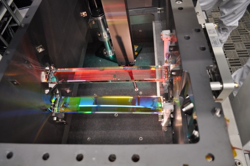
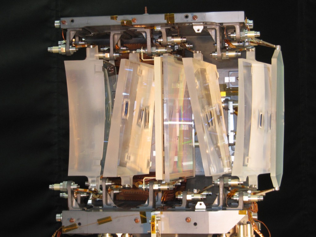
Before reaching the Photometric Instrument detectors, the light passes through two low-resolution fused silica prisms that act as dispersive elements with broadband filters to block unwanted light.
One of the prisms, called the BP for Blue Photometer, operates in a wavelength range of 330-680nm and passes the dispersed light onto a dedicated column of 7 detectors on the focal plane. The RP, Red Photometer, operates in a wavelength range of 640-1000nm and passes its dispersed light onto a separate strip of detectors.
The Photometric Instrument also uses Sky Mapper Data for object tracking and confirmation which means that all objects that are covered by the Astrometric Instrument are also covered by the Photometric Instrument. The 4,500 by 1,966-pixel CCDs are also operated in Time-Delayed Integration mode featuring anti-reflection coatings and quantum efficiencies that are optimized separately for BP and RP.
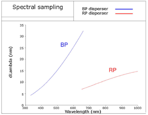
Combined, the two spectra are acquired cover the entire visible spectrum and the near-infrared range. The prisms feature dispersion that is higher at short wavelengths ranging from 4 to 32nm/pixel for BP and 7 to 15 nm/pixel for RP. The two spectra are similar in size, about 45 pixels along scan.
Photometric Data is used to measure the spectral energy distribution of all observed objects. This data serves two purposes: It can be used to correct the centroid positions in the main astrometric field for systematic chromatic shifts. Also, Photometric Data is used to determine physical properties of objects such as effective temperature, mass, age and chemical composition.
Radial Velocity Spectrometer
The final detector array on the focal plane consists of three columns with four CCDs which are dedicated to the Radial Velocity Instrument. Between the M6 mirror and the RVS detectors, an optical module is located. This module consists of a grating plate, a filter plate and four fused-silica lenses that correct the main aberrations of the off-axis field of the Gaia telescopes. The spectral dispersion is located in the along-scan direction. A passband filter restricts the throughput to the desired wavelength range of 847 to 874 nanometers.
RVS also uses the Sky Mapper function for object detection and confirmation while a final object selection is made via data provided by the Red Photometer of the Photometric Instrument.
The CCDs used by RVS are identical to those used for the other instruments. RVS analysis of each observed object will be performed 40 times throughout the Gaia mission.
The high-resolution near infrared spectra provided by RVS provide data on the brightest 150 million stars in the sky (brighter than 17mag)
These spectra provide radial velocity information that are used to study the kinematic and dynamic evolution of the Milky Way. Radial velocities are derived from three isolated Calcium lines at 849.8, 854.2 and 855.2nm. Other lines in the 847 to 874nm range can provide data on star composition, surface gravity, and metal abundance.
Optical Module
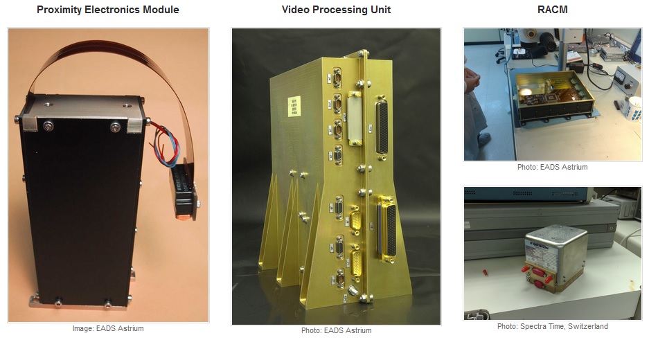
Video Processing Units & Master Clock
Data coming from the CCDs is processed via seven Video Processing Units – one for each row of detectors connected via Proximity Electronics Units and a Interconnection Module. The CCDs provide raw star data to the VPU, which is analyzed and compressed before being passed to the Payload Data Handling Unit (PDHU). Commanding for the Video Processing Units is accomplished via the Control and Data Management Unit.
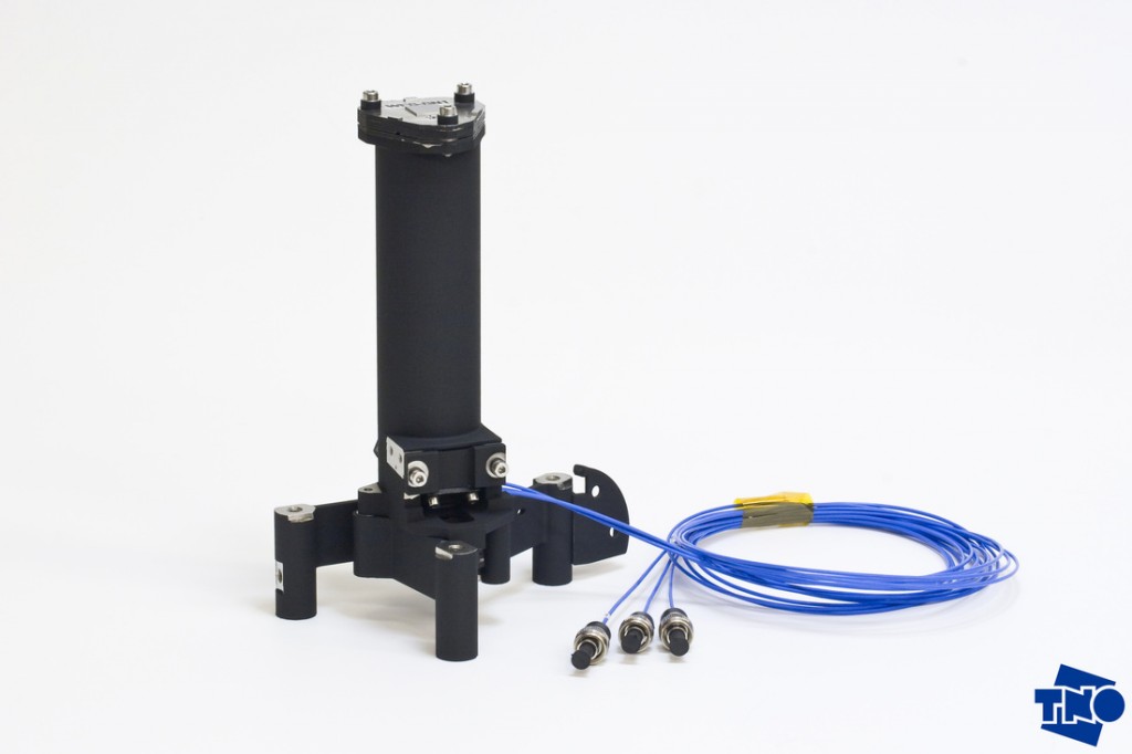
The Gaia scanning algorithm with its window assignment and tracking requires precise timing as the observations are synchronized with spacecraft attitude. Precise timing data for synchronization, CCD timing and data time-tagging is provided by a spacecraft master clock. Gaia carries a Clock Distribution Unit that carries two atomic clocks that build a redundant system. The core of the both clocks is a Rubidium cell, which is integrated into the Rubidium Atomic Clock Module (RACM). Science requirements dictate a time accuracy of ten nanoseconds over a six-hour spin period.
Basic Angle Monitor & Wave Front Sensor
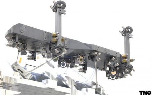
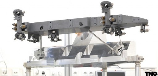
In addition to the scientific sensors, the focal plane hosts another two CCDs that are used to monitor the basic angle with ultra high precision to provide data needed for science data calibration and correction. Also, two Wave Front Sensors are installed on the Focal Plane.
The Basic Angle Monitor consists of two Bars that are installed on the payload torus via isostatic mounts. The two bars face the main mirrors. Each of the bars features a number of beam folding mirrors and bar #2 is equipped with collimating optics, beam splitters and a laser diode acting as a light source.
The collimated light emitted from the point source is split into four beams – two are sent to the main mirror opposite bar #2 and two are sent to bar #1 that directs the light to the other main mirror. The light is then passed from the M1 mirrors to the secondary and tertiary mirrors taking the nominal optical path through the telescope until reaching two dedicated CCDs on the focal plane.
These two CCDs are used to detect the two fringe patterns generated by interference between the pairs of light beams. The differential fringe motion with respect to the detector frame points to the variation in line of sight of each telescope in the along scan direction which corresponds to variations in basic angle.
The basic angle is expected to change by about 7 microarcseconds over the course of a 6-hour rotation of the spacecraft. The monitoring system will pick up changes of less than half a microarcsecond over every five-minute period to provide data used in science data calibration and correction.
Wave Front Sensor