
Falcon Heavy
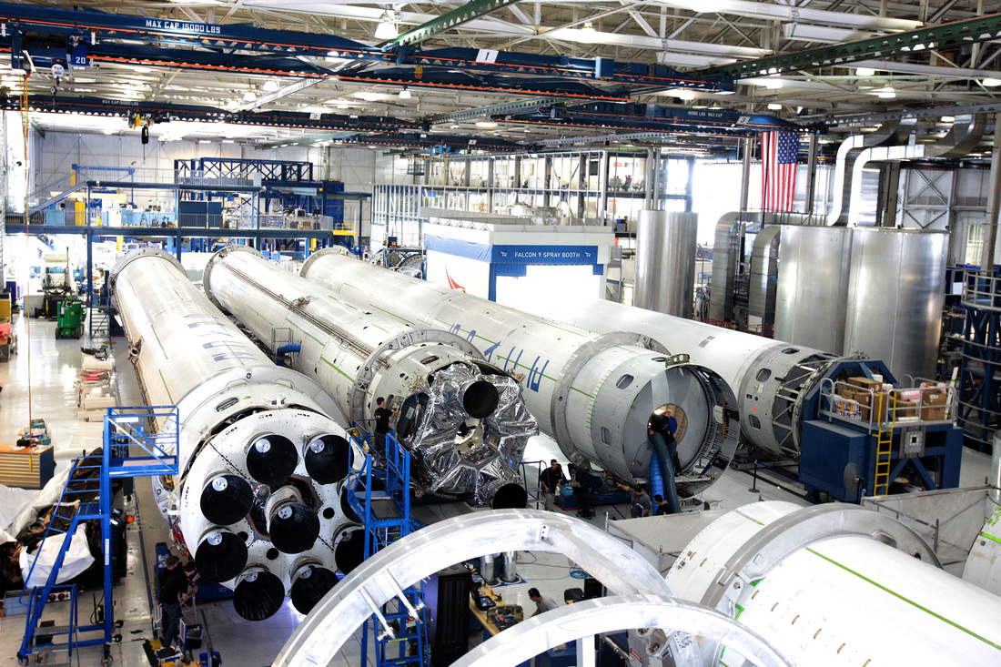
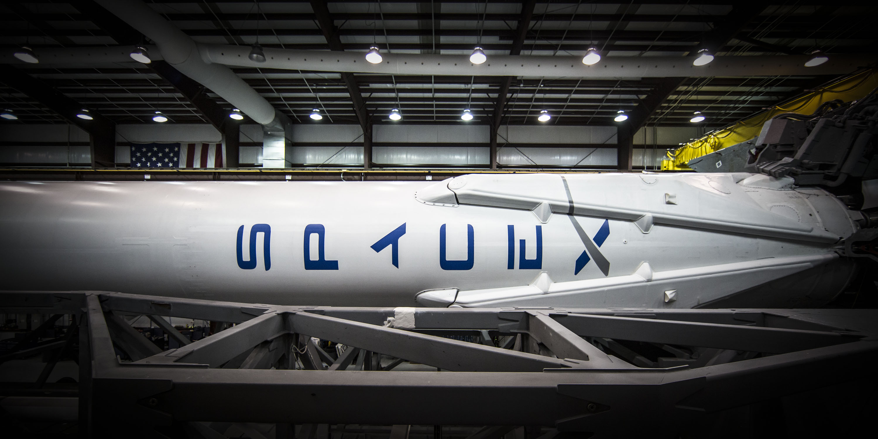
Falcon Heavy is a super-heavy lift space launch system developed and operated by Space Exploration Technologies, SpaceX. Using the company’s Falcon 9 launcher as a basis, Falcon Heavy consists of three F9 cores with a total of 27 Merlin engines, topped by a Falcon 9 upper stage. Operated from Vandenberg Air Force Base and the Kennedy Space Center, Falcon Heavy can be used to access a variety of orbits including Low Earth Orbit, Geostationary Transfer Orbit and interplanetary trajectories. The vehicle includes re-usable technologies and aims to re-use its two side boosters and core stage that make guided boost-back maneuvers and propulsive landings to be refurbished with minimal effort.
Using a standard Falcon 9 and clustering two additional cores to it, Falcon Heavy employs the same overall design principle as the Delta IV Heavy that features three Common Booster Core stages, and the Russian Angara family based on Universal Rocket Modules that can be clustered to cover different payload classes. Falcon Heavy is larger than these two launchers and capable of reaching twice the payload capability of the Delta IV Heavy which currently is the most-powerful space launch system in the world.
SpaceX initiated the development of its heavy launch system in the first half of the 2000s with the goal of creating a launcher that can compete with the world’s heavy lifters such as Delta IV Heavy and Ariane 5 on the commercial launch market, focused on commercial satellites headed to Geostationary Transfer Orbit. Originally, Falcon Heavy was planned to make its first flight two years after Falcon 9, starting out as “Falcon 9 Heavy” since another version based on the now-canceled Falcon 5 was also planned.
Initial performance data for Falcon Heavy was published by SpaceX in 2006 showing a Low Earth Orbit payload capability of 24,750 Kilograms and a launch cost of $78 million. These numbers changed quite often, usually trending up with LEO capabilities rising to 28 metric tons by 2007 and to 32 metric tons by 2010 with a projected launch cost of $95 million. By 2011, Elon Musk announced that development of the launcher was completed, now using the v1.1 version of Falcon 9 as a baseline which further increased the size and performance of the Falcon Heavy.
Falcon Heavy’s first flight was originally planned out of Vandenberg with an initial target of 2013. After SpaceX took over operation of Launch Complex 39A at the Kennedy Space Center and Falcon Heavy fell behind schedule, its first mission was shifted from the west to the east coast.
In 2015, Falcon Heavy was shown to have a payload capability of 53,000kg into LEO, 21,200kg to Geostationary Transfer Orbit and 13,200kg that can be inserted into a Trans-Martian Trajectory. Performance parameters were revised in 2016 showing Falcon Heavy to be capable of lifting 54,400kg to LEO, 22,200kg to GTO and 13,600kg to Mars when flying in its expendable configuration.
Falcon Heavy employs re-usable technologies that are also used on the Falcon 9 such as grid fins, landing legs and re-ignition capability to fly the outer cores and the core stage back to the launch site or a floating platform in the ocean. Depending on the re-usability mode that is selected, Falcon Heavy will be facing payload penalties.
Falcon Heavy surpasses the payload capability of all current launch vehicles and only falls short to the Saturn V and Energia rockets that were capable of carrying more mass into orbit. All requirements for human-rating are being met or exceeded by Falcon Heavy, broadening its potential future applications.
Falcon Heavy Specifications
| Type | Falcon Heavy |
| Height | 70 m |
| Core Diameter | 3.66 m |
| Launch Mass | 1,420,788 kg |
| Stages | 2 |
| Boosters | 2 |
| Span | 12.2 m |
| Mass to LEO | 54,400 kg (28.5°) |
| Mass to GTO | 22,200 kg (27°) |
| Payload to Mars | 13,600 kg |
| Launch Cost | $90M (<8.0mT), [$130M (>8.0mT)] |
| Total Liftoff Thrust | 22,819 kN (M1D+ Engines) |
| Total Vac Thrust | 24,681 kN (M1D+ Engines) |
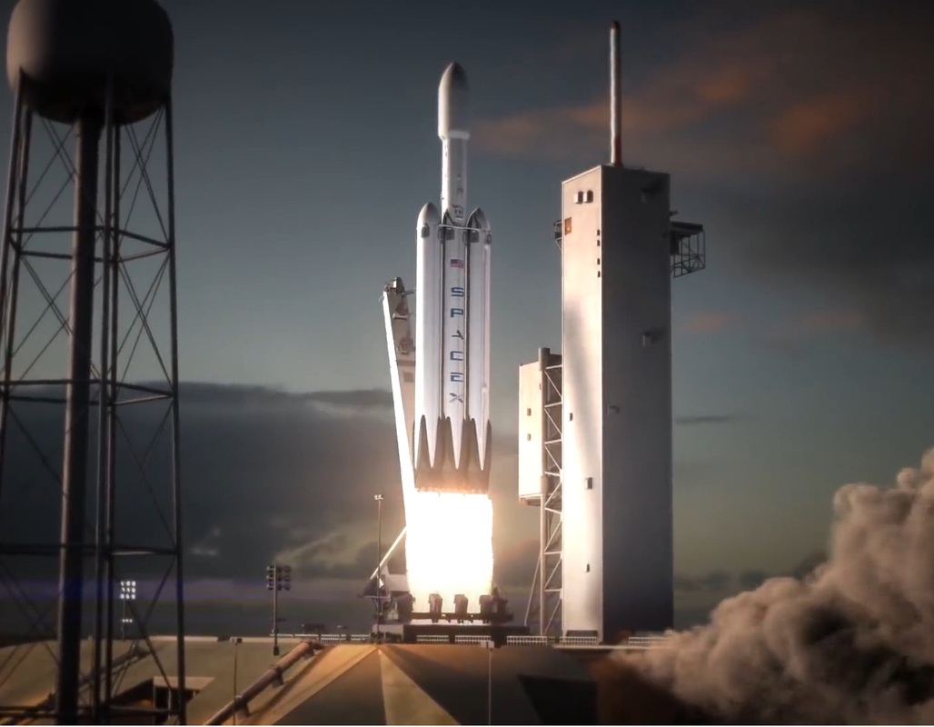
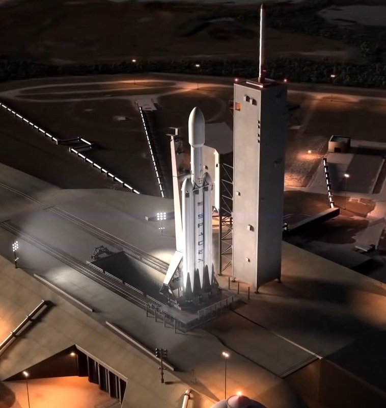
Falcon Heavy stands 70 meters tall with a core diameter of 3.66 meters and a total launch mass of 1,420,800 Kilograms consisting of a Falcon 9 core stage with two cores attached to the central stage functioning as boosters. The launcher uses a standard Falcon 9 second stage and 5.2-meter diameter payload fairing.
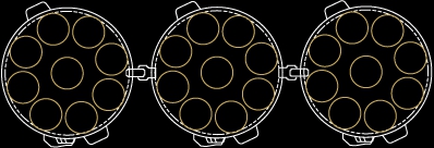
Each of the cores sports nine Merlin 1D engines for a total number of engines on the first stage of 27, only surpassed by the Soviet N1 rocket in terms of the number of engines ignited at liftoff. Propellant crossfeed between the cores is an optional upgrade that will be used for the heaviest payloads, otherwise, the central core would throttle down its engines to be able to burn beyond the propulsion phase of the outer cores. The second stage is equipped with a Merlin 1DVac engine optimized for operation in vacuum.
All stages of Falcon Heavy use chilled Rocket Propellant 1 fuel and sub-cooled Liquid Oxygen oxidizer, employing propellant densification to optimize the mass fraction of the vehicle, further pushing payload capabilities and allowing Merlin 1D+ to operate at its full potential.
Core Stage & Merlin 1D Engine
| Type | Falcon Heavy Core |
| Length | 42.6 m |
| Diameter | 3.66 m |
| Inert Mass* | 25,600 kg |
| Propellant Mass | 411,000 kg |
| Fuel | Rocket Propellant 1 |
| Oxidizer | Liquid Oxygen |
| RP-1 Mass | 123,570 kg |
| LOX Mass | 287,430 kg |
| LOX Tank | Monocoque |
| RP-1 Tank | Stringer & Ring Frame |
| Material | Aluminum-Lithium |
| Guidance | From 2nd Stage |
| Tank Pressurization | Heated Helium |
| Propulsion | 9 x Merlin 1D+ |
| Engine Arrangement | Octaweb |
| Engine Type | Gas Generator, Open-Cycle |
| Propellant Feed | Turbopump |
| M1D+ Thrust (100%) | Sea Level: 845kN – Vac: 914kN |
| Engine Diameter | ~1.0m |
| Engine Dry Weight | 470kg |
| Burn Time* | 230s |
| Specific Impulse | 282s (SL) 311s (Vac) [for M1D] |
| Chamber Pressure | >110 bar |
| Expansion Ratio | 16 |
| Throttle Capability | 55% to 100% (Possibly Deeper) |
| Restart Capability | Yes (Partial) |
| Ignition | TEA-TEB |
| Attitude Control | Gimbaled Engines (pitch, yaw, roll) |
| Cold Gas Nitrogen RCS | |
| 4 Grid Fins (S1 Interstage) | |
| Shutdown | Commanded Shutdown |
| Stage Separation | Pneumatically actuated |
| mechanical collets |
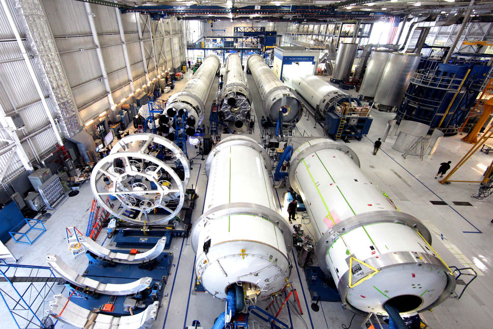
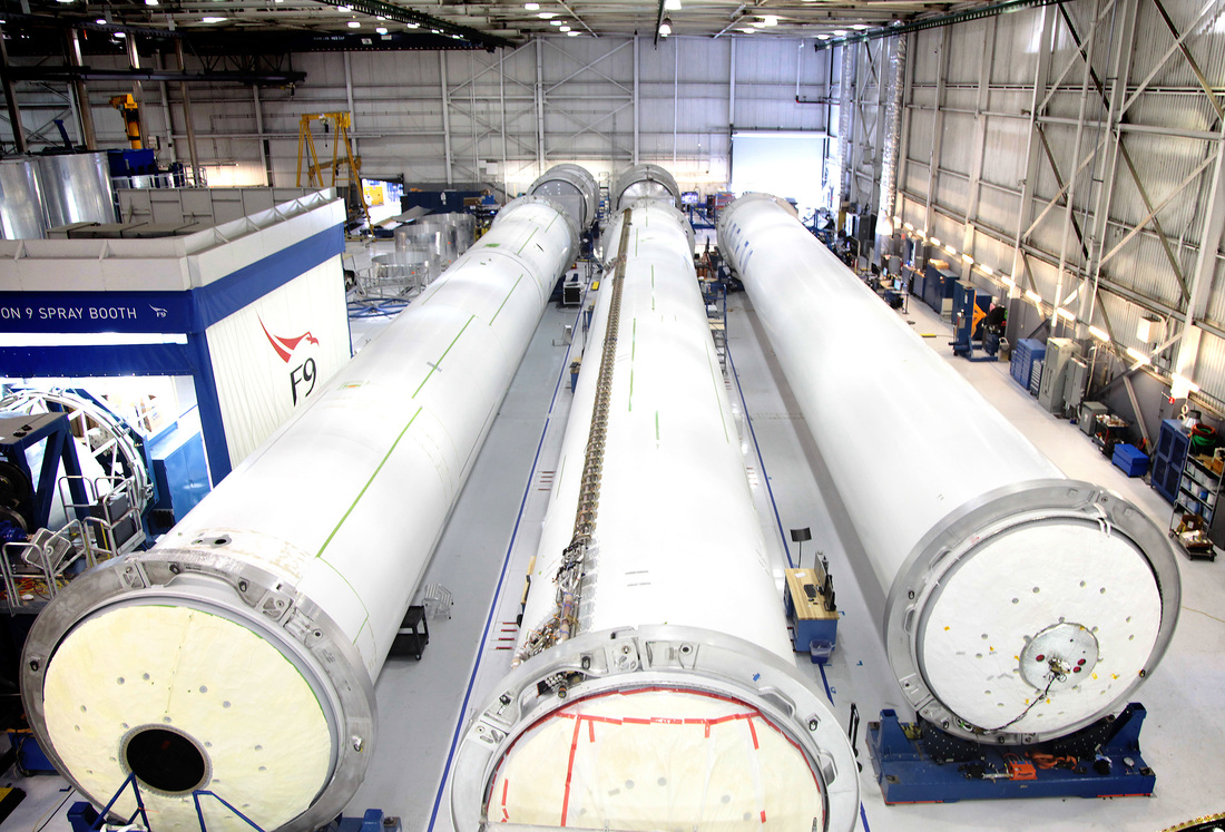
Falcon Heavy uses a central core stage that represents a reinforced Falcon 9 core with a strengthened thrust structure and interfaces for the two boosters in the forward and aft segments.
The Core Stage of Falcon Heavy stands about 41.2 meters tall and is 3.66 meters in diameter featuring the standard design with the oxidizer tank located above the fuel tank. Monocoque structure is utilized on the oxidizer tank while the fuel tank features a stringer and ring-frame design that adds strength to the vehicle. The first stage tank walls and domes are made from aluminum lithium alloy and utilize reliable welding techniques to provide maximum strength.
All components of Falcon 9 and Falcon Heavy are designed with structural safety margins 40% above the expected flight loads, higher than the 25% margin that has become the standard in the industry.
The first stage uses sub-cooled Liquid Oxygen oxidizer and chilled Rocket Propellant-1 as fuel which is highly refined Kerosene. The 10-centimeter LOX feedline is routed through the center of the fuel tank to supply oxidizer to the engines.
The exact dimensions and mass of the core stage are unknown, but calculations indicate that it is capable of carrying roughly 411,000kg of propellants when prop densification is employed. The stage is about 42.6 meters in length (without interstage), 3.66 meters in diameter and has an empty mass of about 24 to 27 metric tons.
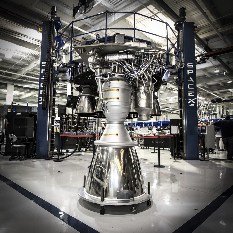
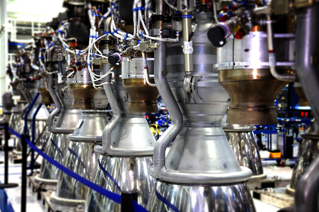
Falcon Heavy sports nine Merlin 1D engines on each of its cores. Compared to its 1C predecessor, Merlin 1D uses improved manufacturing and quality control techniques to enable SpaceX to produce a greater number of engines per year while reducing overall risk. The M1D design is simplified over the M1C by removing no-longer-needed subassemblies. Electro-plating of a nickel-cobalt alloy on the chamber to create the jacket that endures the primary stress of the pressure vessel was replaced by using an explosively formed metal jacket. These changes provide the Merlin 1D with an increased fatigue life and greater thermal margins for the chamber and nozzle which come into play when operating the M1D in an enhanced setting, here referred to as M1D+.
Merlin 1D is an open-cycle gas generator engine. The gas generator operates fuel-rich, burning a small fraction of the LOX and RP-1 flow from the turbopumps to generate a hot high-pressure gas that drives a single turbine with the two turbopumps being driven by a single shaft. High-pressure RP-1 from the fuel turbopump is used in the hydraulic actuators that gimbal the nine main engines for thrust vector control. Generator gas flows through a heat exchanger which heats up Helium gas for tank pressurization in flight before the generator gas is being dumped overboard through an exhaust.
The Kerosene flow from the pump is directed to the combustion chamber and nozzle where it passes through heat exchangers as part of the regenerative cooling scheme of the engine. After passing through the heat exchangers, the fuel is pumped into the combustion chamber where it comes into contact with the oxidizer.
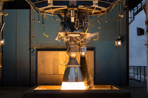
Merlin 1D+ operates at a high chamber pressure of over 110bar to generate a sea level thrust of up to 845 Kilonewtons (86,200kgf) and a vacuum thrust of 914kN (93,200kgf) – giving Falcon Heavy a total liftoff thrust of 22,819kN (2,327,000kgf), rising to 24,681kN (2,468,000kgf) in vacuum.
Merlin 1D+ – as part of its initial performance enhancement – was operated at a sea level thrust of 756kN and a vacuum thrust of 825kN. The throttle setting on the engine will be raised in 2016 based on the performance of the launcher in its initial missions and delta-qualification testing conducted with the revised performance parameters.
Vehicle control is provided by gimbaling the nine Merlin engines when the core stage is on its own, the outer boosters can also individually gimbal their engines.
The engine has an increased expansion ratio of 16 while the M1C engine had an expansion ratio of 14.5. At a mass of 470 Kilograms, Merlin 1D achieves a thrust to weight ratio of 198 – the highest thrust-to-weight ratio in the liquid-fueled engine world. Merlin 1D uses a pyrophoric mixture of Triethylaluminium-Triethylborane (TEA-TEB) as igniter which is injected into the gas generator and combustion chamber to initiate the combustion process that is sustained as LOX and RP-1 flows into the GG/Chamber once turbopumps spin up, initially using high-pressure helium for spin-up.
Also, the engine has a deep throttling capability which allows Falcon to fly a flexible mission profile. The baselined throttle capability ranges from 55 to 100% of rated performance, however, there are strong indications that M1D can throttle down to 40%. To facilitate the propulsive return of the cores, a subset the Merlin 1D engines of the first stage feature onboard re-ignition systems to be fired several times in flight.
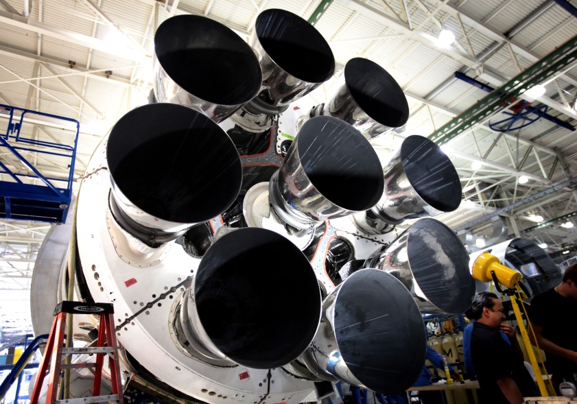
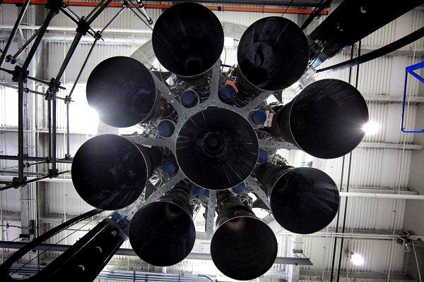
All three cores of the Falcon Heavy feature the “Octaweb” engine arrangement. Eight engines are arranged in a circle – clustered around a single Merlin 1D in the center that is installed slightly lower with its nozzle protruding the others. The gas generator exhaust pipes of the individual engines installed on the perimeter of the first stage are arranged toward the inboard direction, their flow passing through the gap between the center and the outer engines, transporting excess heat out of the engine compartment.
The skin of the launcher is the primary load path for the launch vehicle and arranging most of the engines on the perimeter of the skin eliminates a lot of structure that needs to be installed to carry loads from the engines to the skin. The original tic-tac-toe engine pattern required these load-transferring structures, adding to the overall mass of the vehicle. The new engine arrangement also improves thermal properties as it avoids hot spots.
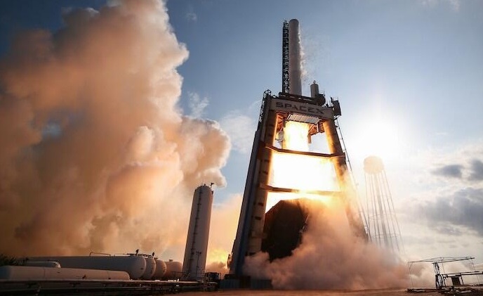
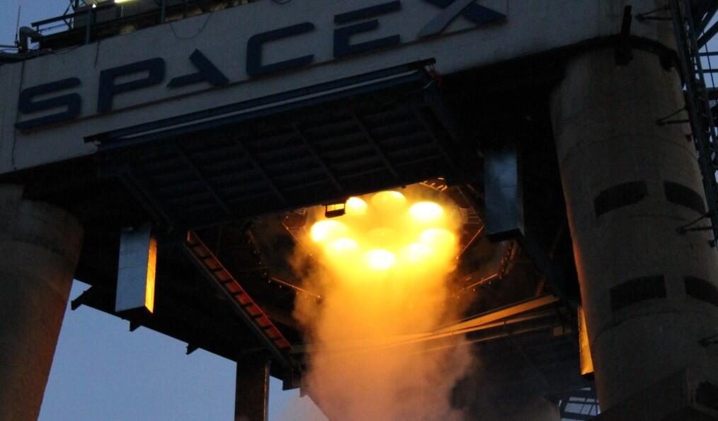
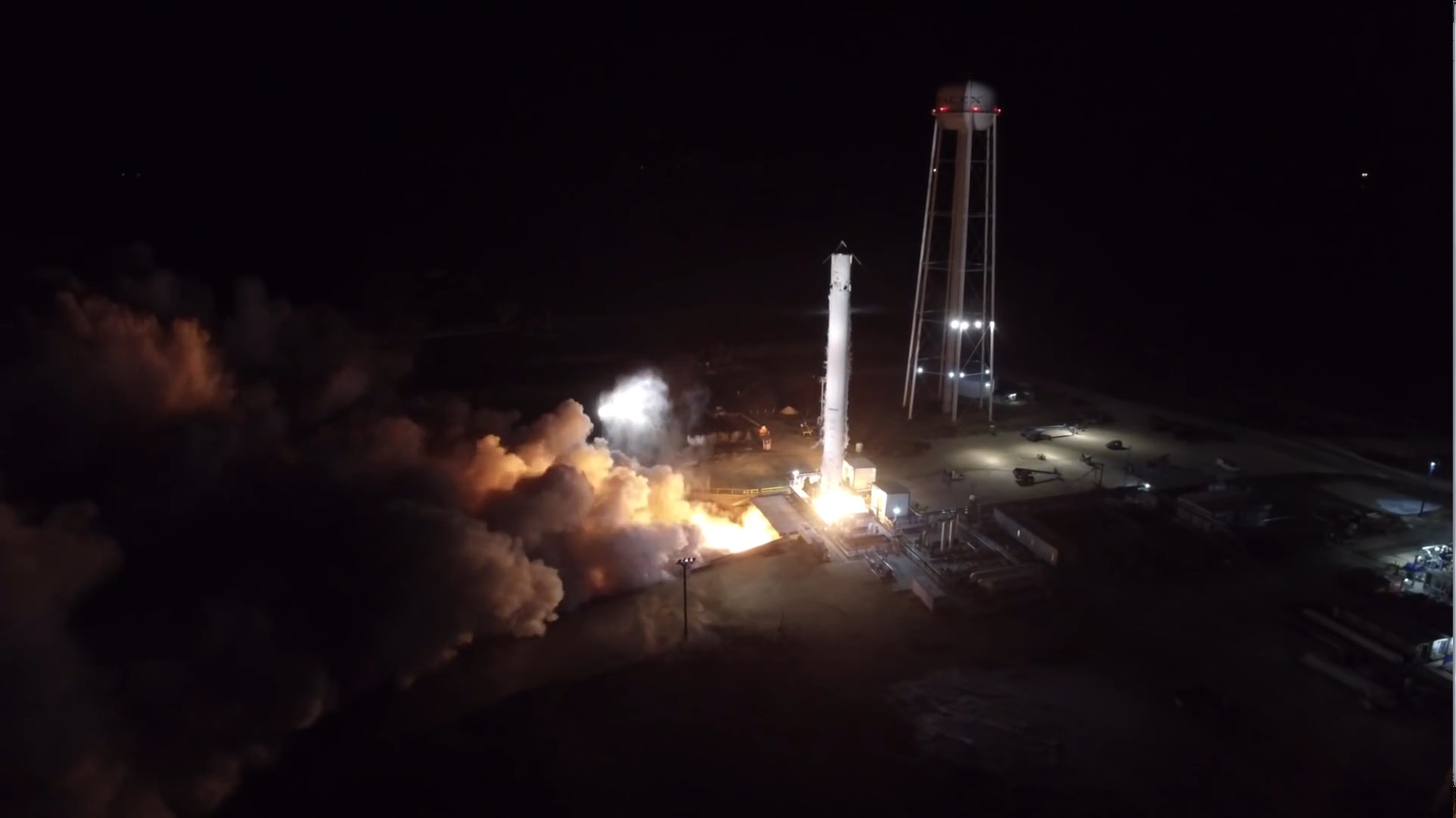
Just like the Falcon 9, FH provides engine-out capability for a large portion of its first stage flight. All 27 engines are ignited on the ground, about three seconds before launch. All must reach operational conditions and liftoff thrust for the launch release command to be issued.
The engines are monitored constantly in flight and computers can shut down any engine at any time to prevent RUD (rapid unplanned disassembly). Following the unplanned shutdown of an engine, the flight computer would re-plan the ascent trajectory to reach the cutoff target with the remaining engines by extending their burn and potentially cutting a booster return, forgoing re-usability to ensure success of the primary mission.
Flying 9 Merlin engines per core provides engine-out capability and it also allows Merlin 1D to quickly build up flight heritage as each mission provides performance data on 27 engines instead of a single engine that competing launchers are using. The core stage and boosters are equipped with a cold-gas Reaction Control System using Nitrogen for three-axis control during coast phases and during single-engine burns.
Each of the Falcon Heavy cores employ an S-Band communications system to transmit 3,000 channels of performance telemetry throughout the flight and after stage separation. The cores are equipped with a Flight Termination System consisting of two strings of transmitters, receivers and safe and arm devices. The FTS works with C-Band Communications and can be used to terminate the flight in case of any major anomalies. Falcon Heavy has autonomous flight termination capabilities triggered by significant systems damage, most likely employing a break-wire type system. Flight termination is accomplished by splitting open the propellant tanks of the vehicle, rendering the rocket non-propulsive.
The cores are equipped with a triple-redundant flight control system as well as a navigation platform using GPS and Inertial Measurement Units to be used during flight in cooperation with the main flight computer on the second stage and as the primary controller during the descent towards the landing site.
The core stage is connected to the second stage via a carbon fiber aluminum core composite structure acting as interstage adapter, housing the MVac engine of the second stage as well as first stage hydraulics equipment for the Grid Fin System and the cold gas attitude control system. The interstage has to carry the entire weight of the second stage and spacecraft. Stage separation is accomplished via separation collets and pneumatic pushers in four interfaces connecting the two stages. SpaceX tries to avoid using pyrotechnics for separation events. A fourth pusher interface was added to make the separation between stages more reliable.
Merlin 1D Performance Enhancement
SpaceX is attempting to get the most possible performance out of the Falcon Heavy launch system without significant design changes to the launch vehicle itself. Increasing performance of the launcher leads to a greater payload capability or a greater margin for the propulsive return of the first stage, either to the launch site or the Autonomous Spaceport Drone Ship depending on the energy requirements of the specific mission.
Using improved manufacturing techniques and materials, the Merlin 1D engine was developed with a great margin in operational conditions and a high degree of durability which would enable the engine to operate at higher thrust levels, pressures and temperatures than originally envisioned. In a 2013 press briefing, SpaceX CEO Elon Musk stated that Merlin 1D, at the time, was being operated at around 85% of its potential and work was underway to certify the Full Thrust setting of the engine for flight. Development and certification testing of the original Merlin 1D finished in mid-2012 and the engine flew for the first time in 2013. Testing of the engine at full thrust began afterwards followed by qualification testing in the summer of 2015.

Perhaps SpaceX was already looking toward Falcon Heavy when designing the Merlin 1D for operation at this increased thrust setting. Running the engine at a greater propellant mass flow rate will lead to a higher chamber pressure and chamber temperature, increasing the overall stress on the engine which has been accounted for in the initial design of the Merlin 1D.
A further increase in Merlin 1D thrust was revealed by Elon Musk in late April 2016. According to Musk, good performance of the engine in its first missions and delta-qualification testing will allow SpaceX to further raise the engine’s performance, currently expected at some point in 2016.
The latest numbers published on the performance of the Full Thrust version of the Merlin 1D engine specify a sea level thrust of 845 Kilonewtons, representing a 24% increase over the initial M1D version and an 11% over the first M1D+ running at 756kN. In vacuum conditions, the Merlin 1D+ engine delivers 914 Kilonewtons of thrust.
These numbers further cement Merlin 1D’s position as the most powerful engine ever built in terms of Thrust to Weight Ratio. The improved Merlin 1D Vacuum engine uses an extended nozzle design and achieves a thrust of 935 Kilonewtons, representing a 17% increase in thrust. (Additional specifications and details on the Merlin 1D engine can be found in the sections below.)
Using this engine on the Falcon 9 rocket leads to more launch thrust, but to accommodate the greater propellant mass flowrate and achieve the desired increase in performance, the rocket needs to launch with a greater propellant mass which can either be achieved by further expanding the tanks or densifying the propellants. Because the dimensions of the first stage of Falcon 9 was maxed out with the upgrade to the Falcon 9 v1.1, SpaceX decided to implement propellant densification.
Propellant Densification
To accommodate the more powerful Merlin 1D engines running at their full thrust setting, Falcon Heavy employs propellant densification and a change in tank sizes to increase the mass of propellants it can hold. The performance gained by Falcon Heavy arises from increasing the total propellant mass in both stages for an improved propellant mass fraction and a longer burn time.
Elon Musk stated that propellant densification capability would be added to all SpaceX launch facilities and all Falcon Heavy missions will rely on densification. Densifying propellants is possible through cooling – increasing the mass than can be loaded into the limited tank volume of the launcher.
NASA studies have shown that LOX densification can increase the oxidizer mass by 8 to 15% compared to boiling-point LOX at –183°C.

Cooling LOX below its boiling point is possible through the use of a Nitrogen subcooler that employs a Liquid Nitrogen bath (either at boiling point or sub-cooled) through which the LOX lines are running to allow an exchange of heat.
SpaceX employs LOX at a temperature of approximately –207°C, about 10°C above the Oxygen Triple Point achieved by running the LOX through a Nitrogen bath that is kept at a partial vacuum to decrease its temperature to nearly N2 ice temperature. This will yield an increase in LOX density from 1.134 grams per cubic centimeter to nearly 1.23g/cm³ while still maintaining the LOX below its freezing point and slush density of 1,338g/cm³. Cooling the LOX to this temperature point yields a density increase of around 8%.
Operational launchers that employ sub-cooled LOX are Antares (in its original version, using LOX at –196°C) and Soyuz 2-1v (-192°C LOX), but in these cases, sub-cooled LOX is/was required due to the design of the engine.
Cooling the fuel, Rocket Propellant 1 (Kerosene), is also possible, although its high freezing temperature of approximately –37°C and changes in viscosity as a function of temperature represent limitations when cooling the fuel. SpaceX chills the RP-1 from ambient temperature down to approximately -7°C where viscosity does not yet affect the properties of the fuel, but achieves an increase in density around 2.5 to 4%. Calculations show that Falcon Heavy consumes RP-1 at a density of 0.86g/cm³.
Because of the different densification possible for LOX and RP1, an adjustment of tank sizes on the rocket is necessary to keep the Oxidizer to Fuel ratio required by the Merlin 1D engines.
This is accomplished by shortening the LOX tank on the first stage and stretching the RP-1 tank while retaining the original first stage length. Stretching the first stage beyond the length of the v1.1 first stage is not possible due to bending forces occurring in flight. Widening the diameter of the stages is also no option because of the requirement of road transport, putting a limit on the maximum diameter. The second stage of Falcon Heavy accommodates the required change in RP-1 volume by stretching the stage.
Falcon Heavy Boosters
| Type | Falcon Heavy Booster |
| Length* | 44.6m |
| Diameter | 3.66m |
| Inert Mass* | 22,500kg |
| Propellant Mass | 411,000kg |
| Fuel | Rocket Propellant 1 |
| Oxidizer | Liquid Oxygen |
| LOX Mass | 287,430kg |
| RP-1 Mass | 123,570kg |
| LOX Tank | Monocoque |
| RP-1 Tank | Stringer & Ring Frame |
| Material | Aluminum-Lithium |
| Guidance | From 2nd Stage |
| Tank Pressurization | Heated Helium |
| Propulsion | 9 x Merlin 1D+ |
| Engine Arrangement | Octaweb |
| Engine Type | Gas Generator, Open-Cycle |
| Propellant Feed | Turbopump |
| M1D+ Thrust (100%) | Sea Level: 845kN – Vac: 914kN |
| Engine Diameter | ~1.0m |
| Engine Dry Weight | 470kg |
| Burn Time* | 162s |
| Specific Impulse | 282s (SL) 311s (Vac) [for M1D] |
| Chamber Pressure | >110 bar |
| Expansion Ratio | 16 |
| Throttle Capability | 55% to 100% (Possibly Deeper) |
| Restart Capability | Yes (Partial) |
| Ignition | TEA-TEB |
| Attitude Control | Gimbaled Engines (pitch, yaw, roll) |
| Cold Gas Nitrogen RCS | |
| 4 Grid Fins | |
| Shutdown | Commanded Shutdown |
| Stage Separation | Thrust Struts, RCS |
Like the Delta IV and Angara, Falcon Heavy aims to reduce complexity in its design by using as much commonality between its core stage and the strap-on boosters as possible. For Delta IV and Angara, the boosters are the same dimension as the core, only using aerodynamic caps and attachment mechanisms that make them different from the core. For Falcon Heavy, an initial design called for the boosters to be stretched in order to hold more propellants, however, this design was dropped in favor of one core length with the only difference between booster and core stage being the thrust structure that needs to be stronger on the core since it has to accept the thrust loads from the twin boosters.
The boosters of Falcon Heavy share the 3.66-meter diameter of the core stage which allows the same tools and techniques to be used in the manufacturing process of the tanks. Each of the boosters, topped with a 3.4m composite cap, is approximately 44.6 meters in length and weighs around 433 metric tons (est) when fully fueled for launch. The boosters each use nine Merlin 1D engines also arranged in an Octaweb pattern and each core is outfitted with independent Guidance, Navigation and Control Systems with communication paths between the computers of the central core and the boosters to allow the main flight computers to issue commands to the boosters and separation systems.
Atop each of the boosters sits a nosecone manufactured from composite materials to keep its weight at a minimum. The four grid fins of the boosters are installed in the uppermost portion of the propellant tank structures, matching up in height with the fins of the central core that have been modified, switching positions from the Interstage to the uppermost section of the core stage. Each booster has its own nitrogen cold gas reaction control system and is capable of executing an autonomous return to the launch site to be re-used.
The boosters are attached to the central core stage via structural interfaces in the aft section and interfaces that connect the upper portion of the boosters to the interstage area of the Falcon Heavy via thrust struts to transfer loads to the vehicle. Separation of the boosters is accomplished using collets in the structural interfaces, avoiding the use of pyrotechnics since SpaceX prefers to use systems that can be tested and re-used. The reaction control system of the boosters ensures a clean separation from the core stage.
Throttle-Down vs. Crossfeed
When Falcon Heavy was initially announced, one of its biggest innovations was to be a propellant crossfeed capability between the boosters and the central core. The design called for propellant lines being routed through the interfaces of the cores, delivering propellants from the oxidizer and fuel manifolds of the boosters to a number of engines on the core, allowing these engines to consume propellant from the booster tanks and leaving the tanks of the central core nearly full until the point of separation when interfaces would be isolated and supply switch to the core stage’s own tanks.
This feature was put on the backburner and SpaceX decided to introduce the Falcon Heavy without operational crossfeed system using a partial thrust mode on the core stage to allow it to save propellants that can be consumed beyond the burn of the side boosters. This procedure is also used by Delta IV Heavy and the Angara family, eliminating the additional mass of a crossfeed system that would only be required on flights with extremely heavy payloads. In a nominal flight scenario, Falcon Heavy would take off with all of its Merlin 1D+ engines at full throttle. After the initial climb, the central core would throttle its engines down to a minimal thrust in order to save propellants while the boosters continue to fire at full thrust.
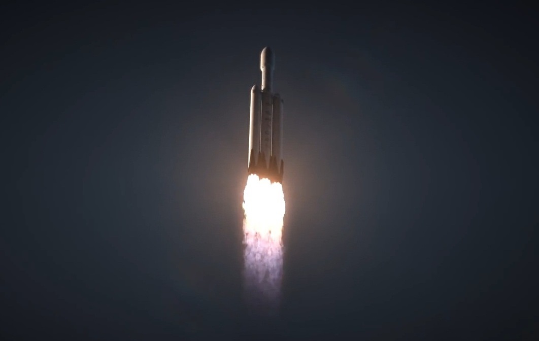
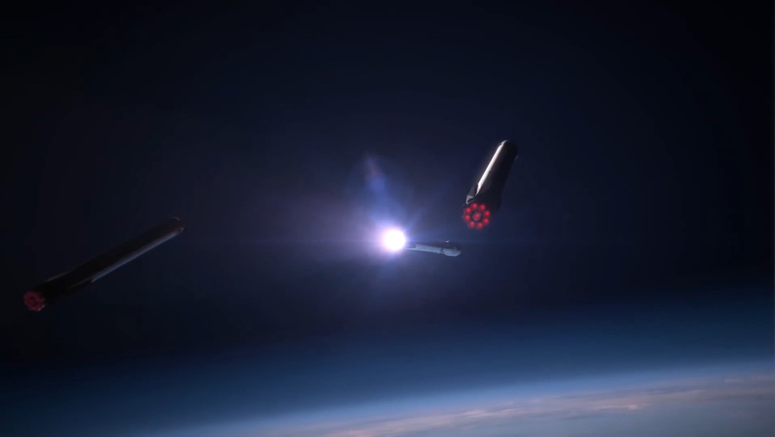
The two boosters would burn for roughly 195 seconds before separating from the core to begin their journey back to the launch site. Continuing powered ascent, the core would throttle up its engines and burn for just over a minute to continue boosting the velocity of the stack, achieving a much higher speed than any previous Falcon cores which makes its recovery more difficult given its much greater energy at separation.
SpaceX is still pressing ahead with the development of the Crossfeed Capability to be used on particular challenging missions with LEO payloads of over 45 metric tons or equivalent payloads to different orbits.
Re-Usable Falcon Heavy
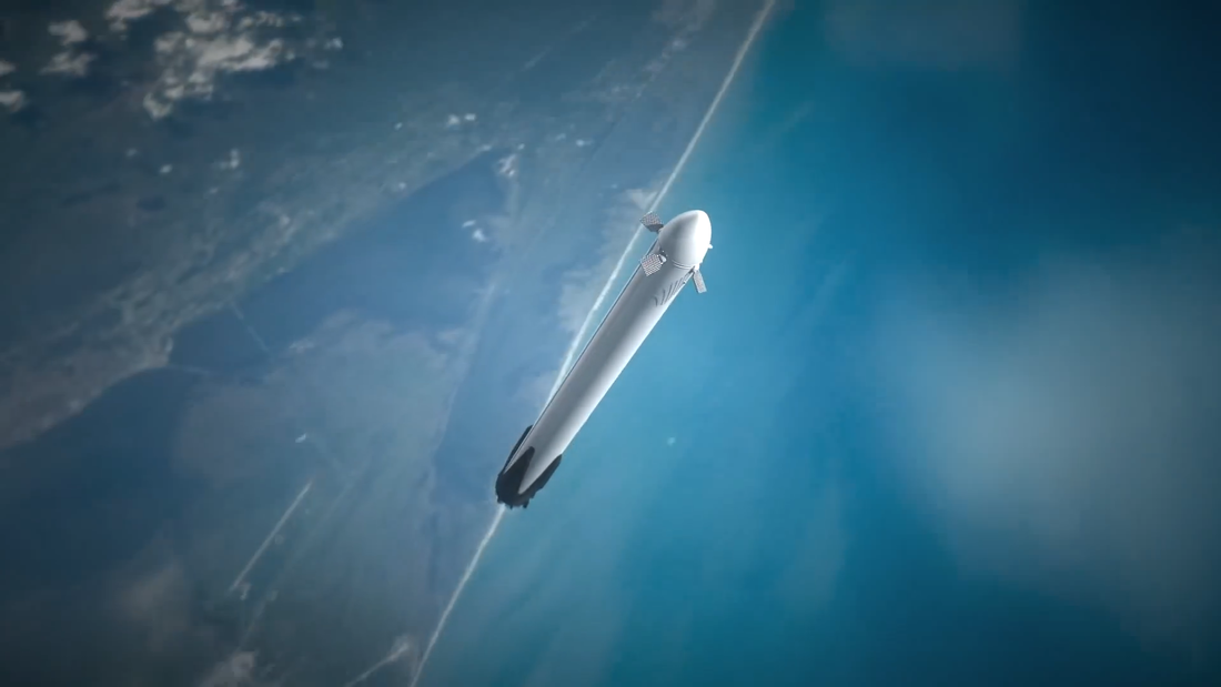
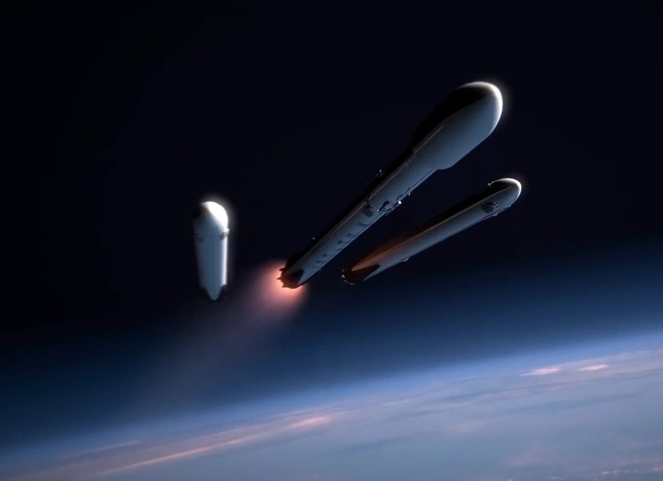
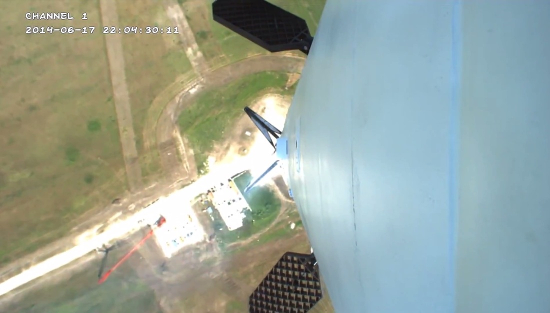
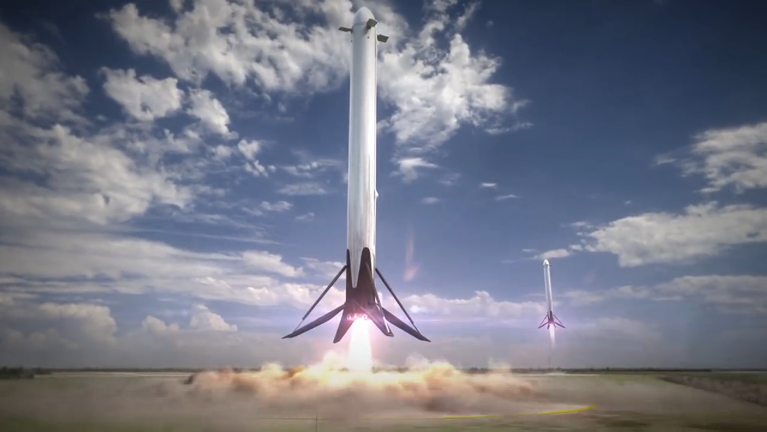
Re-usability of space launch vehicles is one of the biggest goals of SpaceX and Falcon Heavy aims to become the first partially re-usable super-heavy lift launcher. Like Falcon 9, FH will return its three cores to the ground through a series of propulsive maneuvers, a guided flight through the atmosphere and a soft landing on four deployable landing legs – either on land using a flat landing pad to be built near the launch site or on the Autonomous Spaceport Drone Ship inaugurated during the initial tests of returning Falcon 9 boosters to an on-target landing.
The overall goal is to get the rocket stages back to the launch site to avoid the cost of having them returned by ship or other means of transportation. This boost-back to the launch site is feasible for the two outer cores that separate from the launch vehicle at a much lower energy than the central core. Continuing powered flight, the core stage reaches a high energy that would cause a large payload penalty due to the additional fuel required for the boost back to the launch site.
Therefore, SpaceX will keep operating the drone ships (one for the east coast, one for Vandenberg launches and potentially another one for the Brownsville launch site) for the return of the core stages. SpaceX was also looking into the possibility of refueling the cores on the landing platform and having them fly back to land under their own engine power.
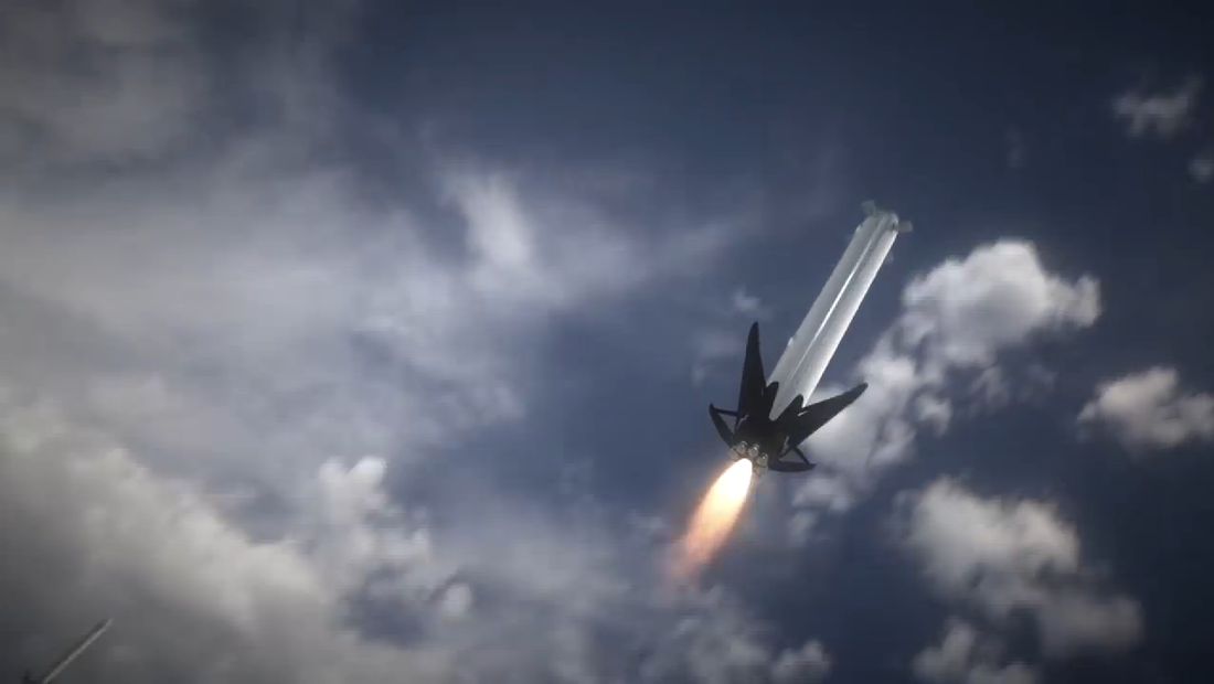
In an operational scenario, Falcon Heavy would blast off and burn its two outer boosters for close to three minutes before the two boosters separate and begin their journey back to the launch site. Immediately, the two boosters would rotate to an engines-first position and make their way to apogee for the boost back burn that would use a subset of the Merlin 1D engines.
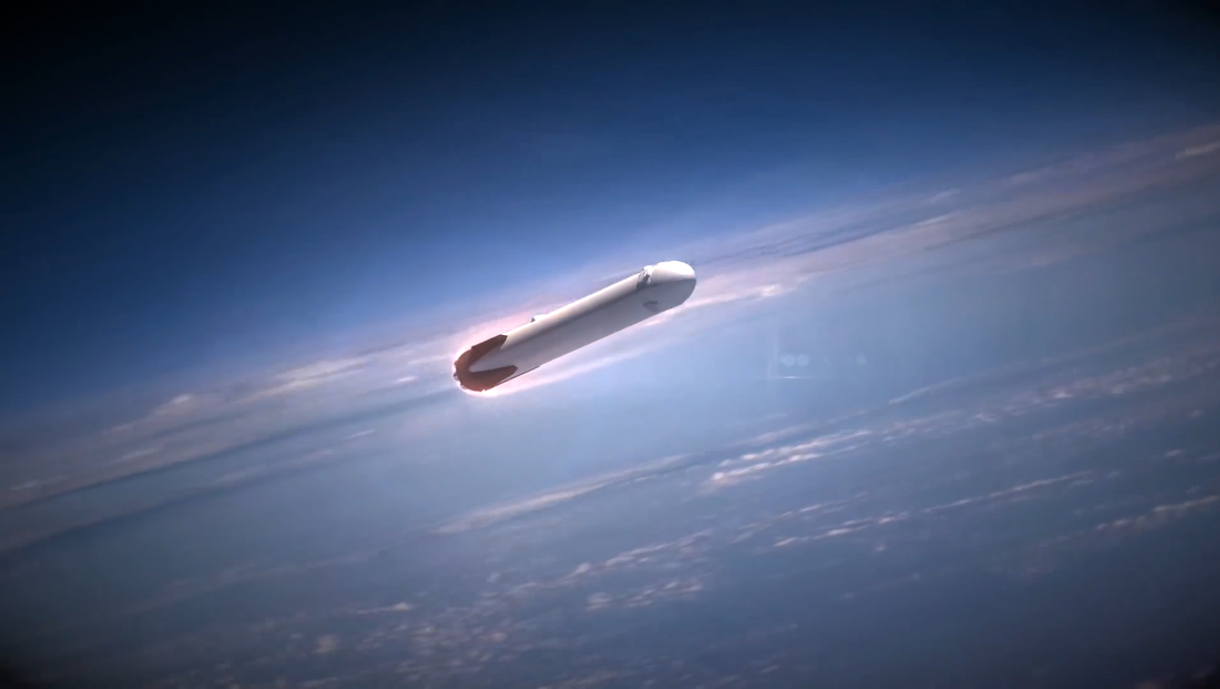
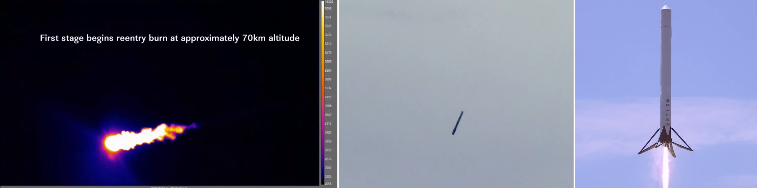
This boost back would reverse the downrange velocity and allow the boosters to begin traveling back to the launch site. Passing through 70 Kilometers in altitude, the boosters would ignite three of their engines for the re-entry burn that serves two purposes – starting to slow the booster down and providing protection to the engine compartment from the aerodynamic re-entry environment. Falcon 9 re-entry burns had a typical duration of 19 seconds.
Beginning their descent through the atmosphere, the boosters would deploy four grid fins for precise steering.
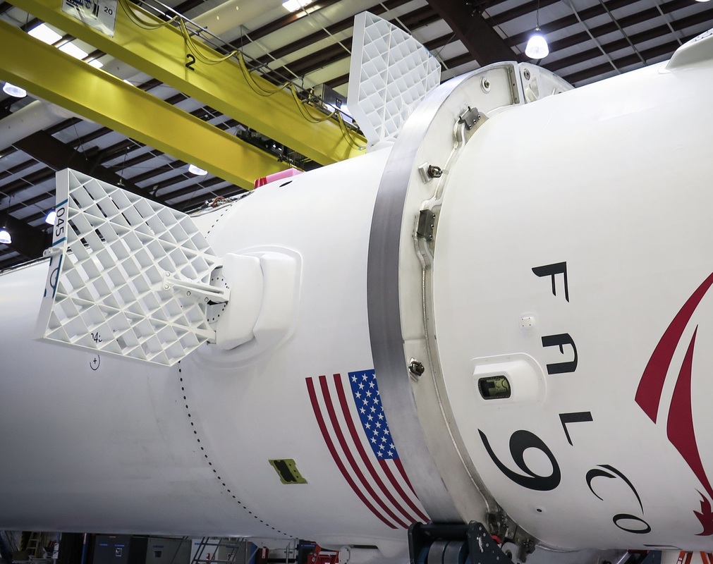
The four grid fins are launched in a position stowed against the uppermost section of the booster near the nose cone before being deployed when Falcon re-enters the atmosphere. The four fins can be individually controlled in a two-degree of freedom type design, rotating and tilting at the same time, allowing for complex guidance and control during atmospheric flight.
The fins are an essential part of Falcon’s return sequence to provide control in atmospheric flight without active propulsion. Grid-fins have been widely used as a stabilizer on missiles & bombs and are shaped like miniature wings consisting of a lattice structure. The Russian Soyuz employs grid-fins in its launch abort system which would deploy when the launch escape rockets start firing in an abort scenario to stabilize the vehicle, but the fins used by SpaceX take it one step further as they can be moved independently to actively control the vehicle’s flight and not only act as a stabilizer.
Grid-fins perform well in all velocity ranges including supersonic and subsonic speeds with the exception of the trans-sonic regime due to the shock wave enveloping the grid. These properties make them ideally suitable for the Falcon booster stages that start out at supersonic speeds and return to subsonic velocity as they travel through the atmosphere, en-route to the landing site. The four fins are rotated and tilted independently by an open hydraulic system that uses pressurized hydraulic fluid supplied from a pressurized tank that is dumped overboard after flowing through the hydraulic actuators of the fin system. The design was also driven by overall mass considerations.
The addition of the grid fins was expected to improve the accuracy of Falcon’s landing by three orders of magnitude – previous landing attempts in the ocean had a ten-Kilometer targeting accuracy while the return to a platform or a pad on land requires the stage to land within a few meters of its bulls-eye target.
Heading back in, the boosters would make final corrections to their flight path, modifying their pitch trim to precisely target their landing site. Around 28 seconds prior to touchdown, the center engine of the booster is re-ignited for the final landing burn. With a limited throttle range, the Center engine will generate a thrust that is greater than the mass of the stage. Landing at a thrust to weight ratio greater than one requires the stages to calculate their propulsive landing maneuver in a way that that reaches a minimum velocity when coming into contact with the ground. Falcon’s boosters are targeting to land at a velocity of less than 6 meters per second.
Ten seconds prior to touchdown, the four landing legs of the booster would deploy. The overall design driver for the landing legs was mass since adding significant weight to the first stage would have resulted in a significant payload penalty. Safety was also a major concern – the leg design had to be such that no premature deployment during powered ascent was possible which would result in a certain loss of the entire vehicle and payload.
Made of aluminum honeycomb and carbon-composite materials, the four legs have a total mass of around 2,100 Kilograms consisting of a single-load bearing strut and aerodynamic fairing assembly. The central struts of the legs interface with the load-carrying structure of the first stage while the fairings have two structural interfaces at the base of the engine compartment heat shield and one interface on the lower portion of the leg
During flight, the legs are stowed against the rocket body, covered by the fairings that ensure no additional aerodynamic disturbance is introduced by the legs. Deployment is accomplished by a pneumatic system using high-pressure helium. When deployed, the legs have a span of about 18 meters, capable of supporting the forces of landing and the mass of the nearly empty booster.
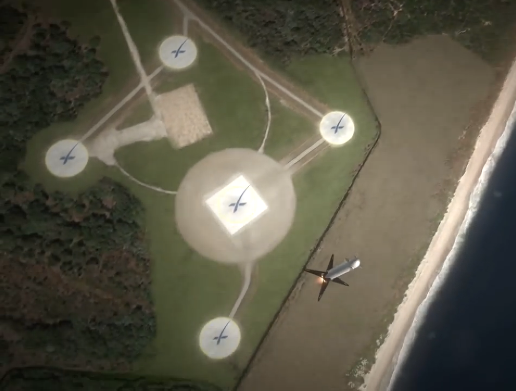
SpaceX has secured properties at Cape Canaveral and Vandenberg Air Force Base to be used as booster landing facilities. At Cape Canaveral, SpaceX signed a five-year lease of Launch Complex 13 in February 2015. An animation of the Falcon Heavy flight profile shows a conceptualized representation of LC-13. Five individual flat landing pads are seen in the animation with four smaller auxiliary pads and one larger central pad. The two boosters use two of the smaller pads, landing within seconds of each other after making their propulsive return from the edge of space.
LC-13 at CCAFS has been in operation from 1958 to 1978 supporting the Atlas launcher family with notable LC-13 launches including Lunar Orbiter 1 and a number of Atlas Agena launch vehicles. The launch pad was not in use for nearly three decades and had its mobile service tower demolished in 2005 followed by the demolition of the blockhouse in 2012. LC-13 will be used to return Falcon stages launching from SLC-40 and LC-39.
At Vandenberg Air Force Base, SpaceX has procured Space Launch Complex 4W for booster landings with SLC-4E serving as Falcon 9 and Falcon Heavy launch pad.
SLC-4W was active for over four decades starting in 1963, supporting Atlas-Agena missions before being converted for the Titan II launch vehicles. In total, SLC-4W saw over 90 launches before becoming inactive after the last Titan 23G launch in 2003. In 2014, the complex was handed to SpaceX and the demolition of existing structures including the Mobile Service Tower started in September 2014. The finished landing facility will likely look very similar to that at Cape Canaveral.
Due to the central core stage of Falcon Heavy continuing onwards after booster separation, it faces a much higher speed when separating from the second stage. A return to the launch site would require a considerable amount of propellant leading to a large payload penalty. Therefore, SpaceX will keep using the Autonomous Spaceport Drone Ships that will be stationed downrange from the launch site to welcome the core stages. The downrange distance of the drone ship will depend on the surplus of propellant that is available for an active boost back.
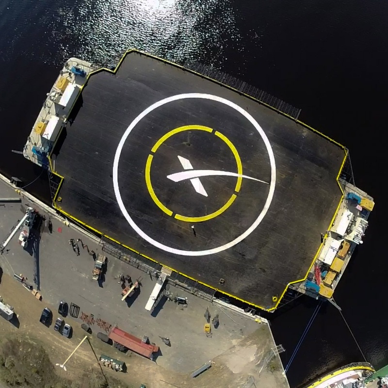
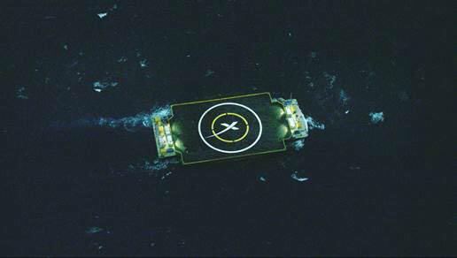
Known as the Autonomous Spaceport Drone Ship, the floating landing platform was built at a Louisiana shipyard and measures 91 meters by 52 meters with a prominent Space“X marks the Spot” logo in the center. The ship sports four diesel-powered azimuth thrusters – similar to those on oil rigs – provided by Thrustmaster, a marine equipment manufacturer that also provided power modules and controls to outfit the ship with a Portable Dynamic Positioning System. Processing GPS data, the Autonomous Spaceport Drone Ship will be able to keep its assigned position with an impressive accuracy of three meters.
A high accuracy is required since Falcon will have to land on the platform with all four of its legs that span approximately 18 meters, leaving just over 30 meters for GPS errors between the two craft and position errors of the drone ship, sea swell as well as errors by Falcon, making its fast-paced hoverslam landing under the power of one of its nine Merlin 1D engines with a thrust to weight ratio greater than one.
The ASDS is outfitted with a water deluge system that dumps water onto the deck to protect it from the heat of the engine of the arriving booster. Numerous attachment fixtures are part of the deck structure that would allow the securing of the first stage after landing on the platform for the return to port and refurbishment.
Flying as fully expendable launch vehicle, Falcon Heavy could deliver 21,200 Kilograms to a standard Geostationary Transfer Orbit. With full reusability on all three cores, the launcher will only be able to put seven metric tons into GTO which is still within the mass range of the heaviest commercial communications satellites. Only returning the boosters and flying the central core as expendable booster will increase GTO capability well over ten metric tons.
Second Stage
| Type | Falcon 9 FT Stage 2 |
| Length* | 12.6m |
| Diameter | 3.66m |
| Inert Mass* | 4,000kg |
| Propellant Mass* | 107,500kg |
| Fuel | Rocket Propellant 1 |
| Oxidizer | Liquid Oxygen |
| LOX Mass* | 75,200kg |
| RP-1 Mass* | 32,300kg |
| LOX Tank | Monocoque |
| RP-1 Tank | Monocoque |
| Material | Aluminum-Lithium |
| Guidance | Inertial |
| Tank Pressurization | Heated Helium |
| Propulsion | 1 x Merlin 1D Vac + |
| Engine Type | Gas Generator |
| Propellant Feed | Turbopump |
| Thrust | 934kN (M1D+) |
| Engine Dry Weight | 490kg |
| Burn Time | 397s |
| Specific Impulse | 348s |
| Chamber Pressure | >110 bar |
| Expansion Ratio | 165 |
| Throttle Capability | Yes |
| Restart Capability | Yes |
| Ignition | TEA-TEB, Redundant |
| Pitch, Yaw Control | Gimbaled Engine |
| Roll Control | Reaction Control System |
| Shutdown | Commanded Shutdown |
| Reaction Control S. | Cold-Gas Nitrogen Thrusters |
Falcon Heavy uses a standard Falcon 9 FT second stage, also employing propellant densification to optimize launch vehicle performance.
The second stage shares its diameter with the first stage and a similar architecture and tank structures with identical construction of tank domes and walls. SpaceX has always followed a policy of choosing simple solutions to reduce cost and risk in order to manufacture a robust launch system. Using the same materials, tools and manufacturing techniques for the two stages is a perfect example of that policy.
The tanks are built using Aluminum-Lithium Monocoque structure for both tanks.
As with the first stage, the exact dimensions of the second stage have not been disclosed by SpaceX. The second stage matches the first stage’s diameter of 3.66 meters. It is approximately 12.6 meters in length without payload adapter and 1st Stage Interstage with an inert mass of around four metric tons. The second stage can hold approximately 75,200kg of LOX and 32,300kg of RP-1 giving it a launch mass of ~111,500kg.
Sub-cooled LOX and chilled Rocket Propellant 1 are also used by the second stage. The difference in densification of LOX and RP-1 requires the Falcon 9 v1.1 second stage RP-1 tank to be stretched in order to keep up the Ox. to Fuel ratio required by the engine.
One Merlin 1D Vac engine is powering the second stage, also operating at its full thrust setting. This engine differs from the first stage engines as it is optimized for operation in vacuum featuring an extended nozzle with a high expansion ratio. Compared to the original M1D design, the M1D+ Vac has an even longer nozzle. It also is a turbopump-fed gas generator engine, operating at a chamber pressure of over 110 bar.
Using an extended nozzle creates a high expansion ratio of 165:1. M1D Vac has a high specific impulse of 348 seconds and generates a total vacuum thrust of 934 Kilonewtons (95,250 Kilograms). The engine can support multiple ignitions to be able to fly a flexible mission profile in order to reach a variety of orbits and trajectories. The second stage TEA-TEB ignition system is fully redundant.
Second Stage Burn time is variable with nominal firings of ~420 seconds.
The second stage is equipped with a Reaction Control System for three axis-control during coast phases and roll control during burns. The Falcon 9 FT uses a cold-gas attitude control system employing a number of Nitrogen thrusters that can support extended mission durations to high-energy trajectories.
The second stage of the Falcon 9 rocket facilitates the avionics and flight computers that control all aspects of the flight. The avionics of the Falcon 9 feature a number of changes and upgrades from the v1.0 to the v1.1/FT version. All avionics and controllers are manufactured in-house by SpaceX. The system is fully redundant, constantly checking itself to verify that all GNC components are functioning properly. SpaceX uses commercial off-the-shelf parts that are radiation tolerant instead of radiation hardened (cost reduction). The flight computers run on Linux with software written in C++.
Avionics are triple redundant and the rocket’s inertial navigation system uses GPS overlay for additional orbital insertion accuracy.
In addition to the main avionics units of the launch vehicle, each of the Merlin Engines is equipped with three processing units in a single engine controller. The engine controller monitors all parameters of the engine and interfaces with the main avionics units. Each of the three processing units are constantly checking on the others to provide fault-tolerance.
Payload Fairing
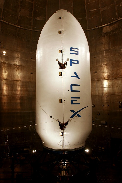
| Payload Fairing | Composite Fairing |
| Diameter | 5.2m |
| Length | 13.1m |
| Weight | ~1,750kg |
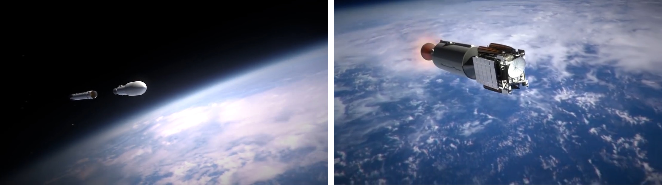
The Payload Fairing is positioned on top of the stacked vehicle and its integrated spacecraft. It protects the vehicle against aerodynamic, thermal and acoustic environments that the launcher experiences during atmospheric flight. When the launcher has left the atmosphere, the fairing is jettisoned. Separating the fairing as early as possible increases ascent performance.
Falcon 9’s standard Fairing is 13.1 meters in length and 5.2 meters in diameter. The fairing consists of an aluminum honeycomb core with carbon-fiber face sheets fabricated in two half-shells. Separation is accomplished via a pneumatic system along the vertical seam that pushes the two halves apart.
Up to three spacecraft access doors or Radio Frequency Windows can be supported by the fairing. A small 3.6-meter fairing is also being developed.
Payload Adapters
Payload Adapters interface with the vehicle and the payload and are the only attachment point of the payload on the Launcher. They house equipment that is needed for Spacecraft Separation and ensure that the payload is secured during powered flight. Electrical and Communication connections are also part of the Adapter and route spacecraft Telemetry to the Flight Computers for downlink. A variety of different adapters is available to suite different spacecraft needs and requirements.
##############################
