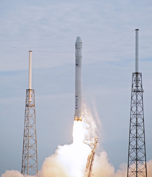
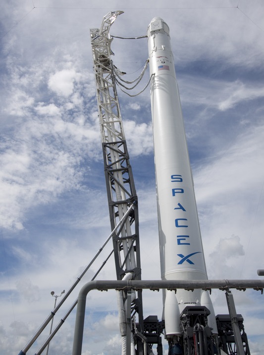
Falcon 9 v1.0 Launch Vehicle
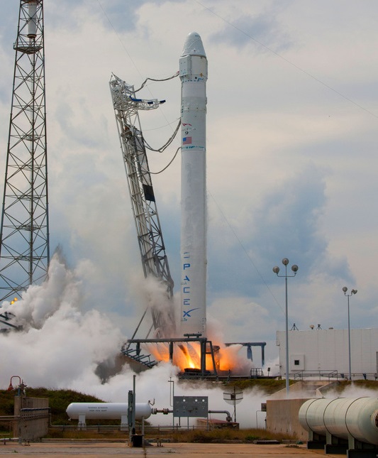
Falcon 9 is a two-stage rocket built and operated by Space Exploration Technologies (SpaceX). The Vehicle is capable of flying multiple satellite mission as well as crewed flights once human-rated.
Based on its capabilities, Falcon 9 is a medium-lift launcher which can place payloads in a variety of Orbits including Low Earth orbit and Geostationary Transfer Orbit. Falcon 9 can be launched from Space Launch Complex 40 at Cape Canaveral Air Force Station, Florida, SLC 4 at Vandenberg Air Force Base and from the Kwajalein Atoll in the Marshall Islands – enabling the Vehicle to reach a variety of orbital inclinations and eliminating the risk of frequent range conflicts.
With the SpaceX Dragon Capsule, Falcon 9 has been awarded a Commercial Resupply Services (CRS) contract from NASA to resupply the International Space Station as part of the Commercial Orbital Transportation Services (COTS) program.
Falcon 9 has been designed with the purpose of crewed space missions in mind so that all systems have full redundancy including several engine-out capabilities during first stage flight. Falcon 9 and Dragon will make 12 ISS Resupply Missions with the option of additional flights and manned missions beyond 2015.
| Type | Falcon 9 Block 2 |
| Height | 55m |
| Diameter | 3.66m |
| Launch Mass | 333,400kg |
| Stages | 2 |
| Boosters | 0 |
| Mass to LEO | 10,450kg |
| Mass to GTO | 4,540kg |
| Launch Cost | 50-56M USD |
To date, Falcon 9 has completed 5 successful missions demonstrating its capabilities and testing maneuvers in space. In the future, Falcon 9 will fly ISS Missions as part of the Commercial Resupply Services and commercial flights to orbit various satellites for different customers including Iridium, Asiasat and SES.
The Falcon 9 Design is based on the light-weight Falcon 1 Rocket that can lift small payloads into Low Earth Orbit. Many elements of the vehicles are similar to reduce design and production costs in order to keep launch prices as low as possible.
Both vehicles utilize a simple design to achieve maximum reliability. Two Rocket Stages reduce the risk of problems during stage separation and the use of 10 engines per vehicle enables the System to gain flight heritage at a fast pace.
Core Stage
| Diameter | 3.66m |
| Length | ~38m |
| Propellant | Rocket Propellant 1 |
| Oxidizer | Liquid Oxygen |
| LOX Tank | Monococque |
| RP-1 Tank | Stringer & Ring Frame |
| Material | Aluminum-Lithium |
| LOX Volume | 146,000 Liters |
| RP-1 Volume | 94,000 Liters |
| Guidance | From 2nd Stage |
| Tank Pressurization | Heated Helium |
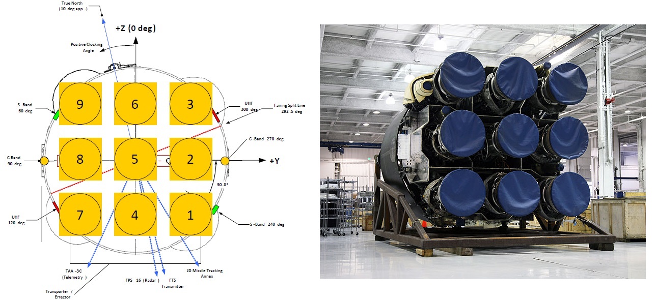
| Propulsion | 9 Merlin 1C |
| Engine Type | Liquid, Gas Generator |
| Propellant Feed | Turbopump |
| Merlin 1 C Thrust | Sea Level: 420kN – Vacuum: 480kN |
| Engine Diameter | 1.25m |
| Engine Dry Weight | 630kg |
| Burn Time | 170s |
| Specific Impulse | 275s (SL) 304s (Vac) |
| Chamber Pressure | 982psi (6.77MPa) |
| Throttle Capability | 100% Only |
| Restart Capability | No |
| Attitude Control | Gimbaled Engines (Pitch, Yaw, Roll) |
| Shutdown | Commanded Shutdown |
| Stage Separation | Pneumatically actuated |
| mechanical collets | |
| Stage Recovery | Parachute |
The first stage tank walls and domes are made from aluminum lithium alloy and utilize reliable welding techniques to provide maximum strength.
Nine Merlin 1C Engines power the first stage with a total of 5 Mega Newtons of Thrust. After engine ignition, all nine engines are monitored for several seconds and good performance is verified before the vehicle is released and lifts off. An autonomous shutdown is conducted in case of a single engine showing off-nominal performance.
Falcon 9 provides Engine-Out capabilities for a large portion of first stage flight, meaning that engines can be shut down should problems emerge and the vehicle could still reach its planned cutoff target by adjusting its flight path accordingly. This makes the Falcon 9 the world’s first Evolved Expendable Launch Vehicle.
First Stage Burn time is 170 seconds after which pneumatic pushers separate the first from the second stage of the vehicle. Thrust Vector Control is provided by gimbaling all nine engines.
The first stage has its own S-Band communication system to send telemetry even after stage separation. SpaceX has designed the first stage to be reusable. For that, the vehicle has a coating ablative cork and a parachute system to land gently in the ocean to be recovered and refurbished. Also, materials used on the vehicle are resistant to salt-water corrosion.
For the first several flights, the first stage will not be re-used as recovery technology is evaluated and improved to lead to a re-usable stage by flight six of the Falcon 9. The Rocket has a Flight Termination System consisting of two strings of transmitters, receivers and safe and arm devices. The FTS works with C-Band Communications and can be used to terminate the flight in case of any anomalies.
The interstage adapter between the two stages is a carbon fiber aluminum core composite structure.
| Diameter | 3.66m |
| Length | ~10m |
| Propellant | Rocket Propellant 1 |
| Oxidizer | Liquid Oxygen |
| LOX Tank | Monococque |
| RP-1 Tank | Monococque |
| Material | Aluminum-Lithium |
| LOX Volume | 27,600 Liters |
| RP-1 Volume | 17,400 Liters |
| Guidance | Inertial |
| Tank Pressurization | Heated Helium |
| Propulsion | 1 Merlin Vacuum |
| Engine Type | Liquid, Gas Generator |
| Propellant Feed | Turbopump |
| Total Thrust | 445kN |
| Engine Diameter | 1.25m |
| Engine Dry Weight | 630kg |
| Burn Time | 345s |
| Specific Impulse | 342s (Vac) |
| Chamber Pressure | 981psi (6.77MPa) |
| Throttle Capability | 60-100% |
| Restart Capability | 2 Re-Starts |
| Pitch, Yaw Control | Gimbaled Engine |
| Roll Control | Gimbaled Turbine Exhaust Duct |
| Shutdown | Commanded Shutdown |
| Reaction Control S. | 4 Draco Engines |
| Thrust | 400N per Draco Engine |
| Fuel | Monomethylhydrazine |
| Oxidizer | Nitrogen Tetroxide |
Second Stage
In essence, the tank assembly of the second stage of the Falcon 9 is simply a smaller version of the first stage’s design to provide a cost-efficient construction.
One Merlin engine powers the vehicle during second stage flight. This engine is a Merlin 1C Model that has been improved for flight in the vacuum of space. It has an expansion ratio of 117:1 and a nominal burn time of 345 seconds. The engine can support up to 2 re-starts.
During a nominal mission, the first burn of the second stage occurs after stage separations to place the vehicle in its preliminary Low Earth Orbit and a second burn later in the mission to increase the stack’s orbital altitude.
After spacecraft separation, the second stage is able to make a deorbit burn and re-enter the atmosphere. It is planned to outfit the stage with a heat shield to be recovered and reused later in the program’s lifetime.
The second stage accommodates the avionics of the Falcon 9 Launcher. Flight computers and navigation system are redundant systems as part of a single-fault tolerant architecture. Controllers for vehicle control are designed and manufactured by SpaceX.
Also located on the second stage is the vehicle’s reaction control system that is comprised of four Draco Thrusters that are powered by Hydrazine and Nitrogen Tetroxide. Each Draco Engine provides 400 Newtons of Thrust. The system is used to control the vehicle’s attitude during coast phases.
Also, the RCS can be used to perform a third phase of powered flight on a nominal mission to Geosynchronous Transfer Orbit. This would be a long burn of the RCS to increase the Apogee of the Payload just before Spacecraft Separation. With only one engine, the second stage does not have engine-out capabilities.
Payload Fairing
| Diameter | 5.2m |
| Length | 13.9m |
| Mass | ~1,900kg |
The Payload Fairing is positioned on top of the stacked vehicle and its integrated spacecraft. It protects the vehicle against aerodynamic, thermal and acoustic environments that the launcher experiences during atmospheric flight. When the launcher has left the atmosphere, the fairing is jettisoned. The fairing then falls back to Earth. Separating the fairing as early as possible increases ascent performance. Falcon 9’s standard Fairing is 13.9 meters in length and 5.2 meters in diameter. Up to three spacecraft access doors or Radio Frequencies can be supported by the fairing. SpaceX also offers custom fairing design to accommodate a variety of payloads and customers.
Payload Adapter
Payload Adapters interface with the vehicle and the payload and are the only attachment point of the payload on the Launcher. They house equipment that is needed for Spacecraft Separation and ensure that the payload is secured during powered flight. Electrical and Communication connections are also part of the Adapter and route spacecraft Telemetry to the Flight Computers for downlink. A variety of different adapters is available to suite different spacecraft needs and requirements.
Injection Accuracy
| Orbit | LEO |
| Perigee | +/- 10km |
| Apogee | +/- 10km |
| Inclination | +/- 0.1 deg |
| Right Ascension of | |
| Ascending Node | +/- 0.15 deg |
| Orbit | GTO |
| Perigee | +/- 7.4km |
| Apogee | +/- 130km |
| Inclination | +/- 0.1 deg |
| Right Ascension of | |
| Ascending Node | +/- 0.75 deg |
| Arg of Perigee | +/- 0.3 deg |