
Electromagnetic Levitator
One of the largest pieces of equipment delivered by ATV-5 is the 360-Kilogram Electro Magnetic Levitator EML that will find its new home inside the Materials Science Laboratory of ISS where it will conduct fundamental research by melting and cooling metals in true microgravity conditions to study underlying processes of metallurgy and materials science.
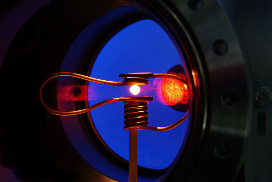
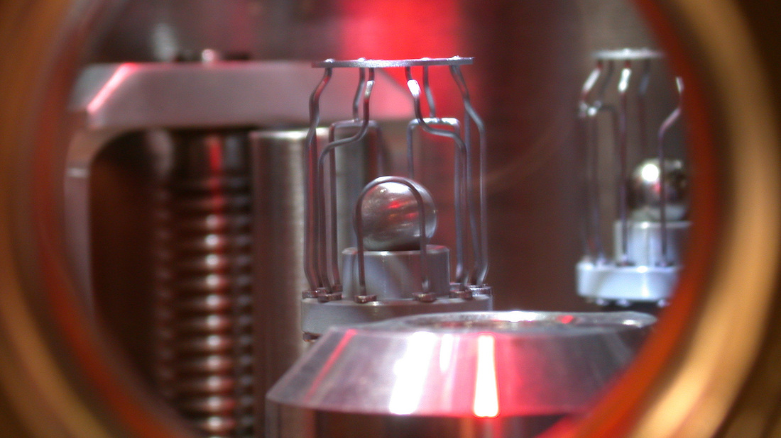
The EML provides containerless melting and solidification of electrically conductive samples in an ultra-high vacuum or a high-purity gas environment. A spherical sample is positioned by a system of coils that hold the sample in a position where it has no contact to another structure for melting at temperatures of up to 2,100°C utilizing Eddy currents that are induced in the sample by the electromagnetic field generated by the coils. Heating is caused by Ohmic losses of the induced currents; the interaction of the Eddy currents with the electromagnetic field causes a displacement force that keeps the sample levitating freely.
Experiment runs can be conducted with a freely floating solid or liquid droplet at a broad temperature range to study material properties at different temperatures and environments. One of the outstanding features of this technique is the possibility of undercooling a sample – keeping it in its liquid state at a temperature well below its melting point due to the absence of nucleation since the material has no contact to any walls.
Electromagnetic levitation is the most mature concept of containerless processing techniques and therefore has been chosen over acoustic and electrostatic levitation. The technique has been applied in microgravity research for decades and its operation is well understood.
Although it is possible to use this technique to create levitation on Earth, but strong fields are needed to overcome gravity which leads to a high starting temperature that is above the melting point of many samples. Also deformation of samples by electromagnetic pressure and strong convections occur in ground-based setups. All these issues can be overcome when conducting the experiment in microgravity.
Only small levitation forces are needed in zero-G to compensate the minimal accelerations that occur in the ISS orbit. Positioning and heating can be performed almost independently of one another due to the low required force and thus the minimum temperature the system can achieve lies considerable under that achievable on Earth. Accuracy of the measurements is significantly higher due to the elimination of convection and deformation.
Previously, electromagnetic levitation was performed on parabolic flights that only offered microgravity for a few seconds at a time, on sounding rocket missions that offered several minutes of microgravity and during spacelab mission during which the several-hour-long runs were often disturbed by crew activity. Having a permanent experiment facility aboard ISS allows access to more experiment runs with more samples that can be inserted into the facility, processed automatically and returned to the ground while experiment runs could be performed during crew nights to eliminate interference.
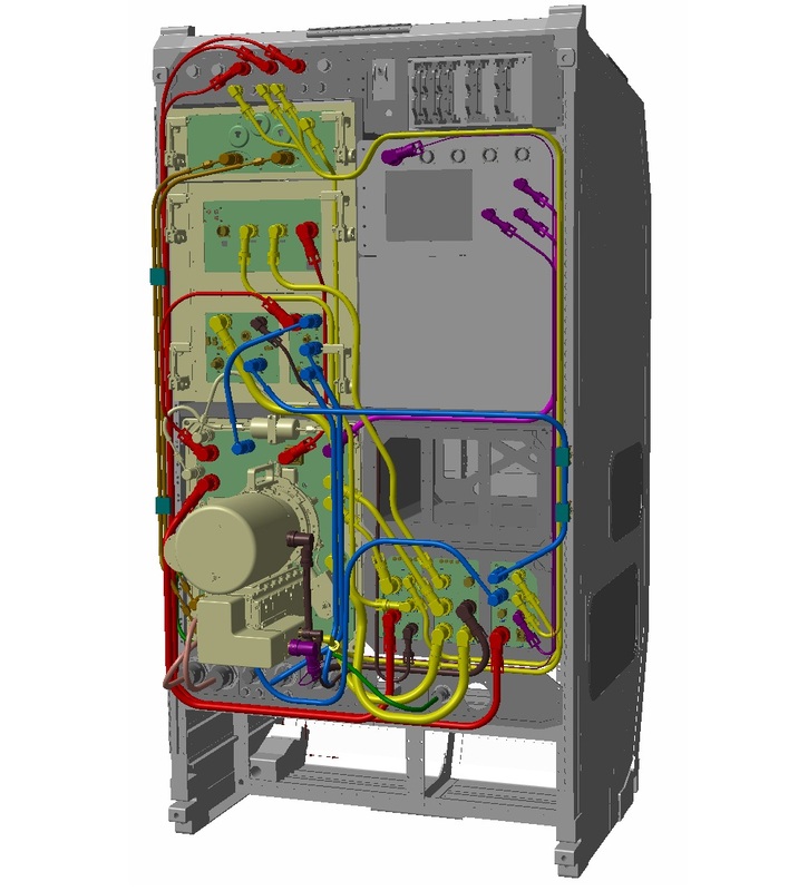
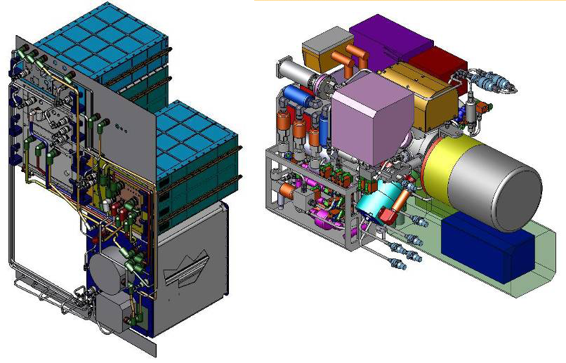
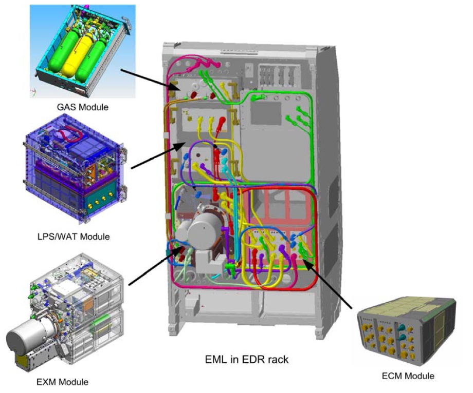
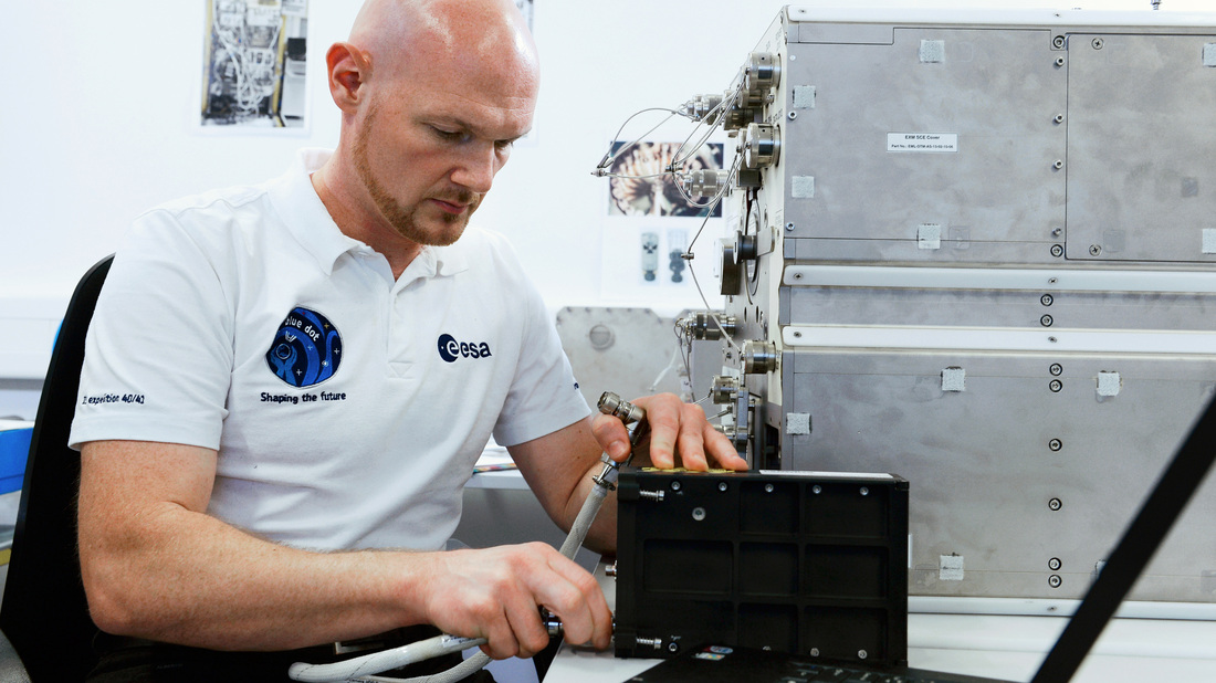
The EML facility consists of four modules that were designed to fit into drawers of the European Drawer Rack of the Columbus module. The payload was developed by Airbus Defence and Space and uses the resources provided by the Drawer Rack (power at 28 and 120 Volts, water and air cooling loops, data and video interfaces, vacuum and vent lines, dry nitrogen purge). EML also requires a number of resources provided by the payload itself such as inert gas, ultra-high vacuum generation and a mass memory for data and video with an associated data management and control system.
The EML payload consists of a Gas Supply Module, a Levitation Power Supply and Water Pump Module, the Experiment Module, and the Experiment Controller Module. The modular design of the payload allows the replacement of entire modules or components making EML a flexible payload – allowing for maintenance and upgrades.
The operation of the payload is mostly automatic – only requiring the crew members to set up the facility, perform regular maintenance and insert/remove sample cartridges. Experiment runs are executed automatically based on parameters loaded by controllers on the ground. For the experiment run, live telemetry and video is needed to allow intervention from the ground in case of instabilities or other issues. For that, the payload provides a rapid reaction time to abort an experiment run on ground command.
The EML Experiment Module houses the core experiment chamber with all its instruments, the RF coil system, sample handling mechanisms and other support equipment.
The chamber itself is a stainless steel ultra-high vacuum chamber. The chamber pressure can vary from 10^-8 mbar in vacuum experiment runs and 400 mbar during inert gas runs that use a 99.9999% pure noble gas (helium, argon or a mixture of the two). The vacuum is achieved using a turbo-molecular pump that interfaces with the ISS vacuum line. Gas is supplied by the gas module and loop gas circulation can be achieved using a gas pump creating a smooth gas flow onto the sample to flush sample particles. When not operated, the chamber is filled with dry nitrogen.

The RF coils that are used to levitate and heat the sample are fed by a Levitation Power Supply, connected to the Coil System Module that features coil network and capacitors which generate the electromagnetic field. The levitation and heating is done at the resonance frequencies of the positioning and heating circuits which requires the system only to compensate for power losses in the circuits that are kept at manageable power levels of around 10A.
The same copper coil is used for positioning and heating as the two fields are superimposed for a high concentricity of the fields and high position accuracy. The quadrupole positioning field operates at 140kHz while the dipole heating field operates at 380kHz – in turn, the positioning field offers low heating efficiency and the heating field causes a low-force so that both are almost independent.
Heating rates of up to 100 Kelvin per second can be achieved with a maximum temperature of 2,100°C that is reached in less than one minute.
EML features a number of accommodations that allow for different stimulation techniques that enable scientists to probe the different properties of a sample at a given temperature profile. Short pulses of the RF heater field lead to low-forces being experienced by the sample. This squeezing motion develops into shape oscillations that can be used to determine surface tension and viscosity. A modulation of the RF heater field with a sinusoidal input power creates a temperature response in the sample that can be measured to learn about the thermal capacity of the material.
A trigger needle made from Rhenium can be used to touch the sample to act as a crystallization trigger which can induce nucleation at undercooling temperatures for high-speed imaging to study the solidification processes. Using a ceramic plate as a heat sink can increase the cooling rate of a sample when being touched by the cooling plate. A small drilling in the plate allows the observation of the temperature development of the interface between plate and sample.
Finally, sample dampening can be used to mechanically dampen oscillations in a sample by moving the sample holder closer to the sample.
EML can accommodate up to 18 samples, each 5 to 8 mm in size. The samples are facilitated in individual sample holders that are installed in a carousel inside the sample chamber that allows the selection of a sample that is then transferred from the storage position to the RF coil for an experiment run and back to the holder when the experiment finished to return to Earth. Sample holders developed for EML include a cup-type and cage design with slit openings for sample observation. The holders consists of ceramics with high thermal stability and no interaction with the electromagnetic field. Silicon nitride is used for the cup holders while tungsten-rhenium is used for the cage.
The experiment is designed for an easy installation and removal of the sample chamber that allows the processed samples to be returned to Earth while new sample chambers can be flown up on different cargo vehicles.
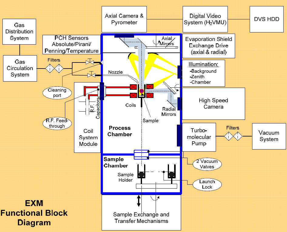
Measurement equipment inside the EML includes a radial high-speed camera and an axial video system to provide imagery of the experiments while a pyrometer is used for temperature measurement.
The highly sensitive digital pyrometer is integrated with the axial camera and observes the sample via an optical path that includes mirrors and a beam splitter that separates the near-infrared spectrum from visible light and directs it to the pyrometer.
The pyrometer operates at a temperature range of 300 to 2,100°C with a temperature resolution of 0.1 K above 600° and a lower resolution as temperatures get lower. It can work at a measurement rate of 100 Hz with an integration time of 5ms. It detects wavelengths of 1.45 to 1.80 micrometers. The pyrometer spot on the sample is 0.8 millimeters in diameter.
Installed in a single package next to the pyrometer is the axial camera that is used for digital high resolution observation of the sample. Being mounted in an axial geometry, this camera is used to observe the fast oscillations of the sample for viscosity and surface tension measurement as well as thermal expansion measurements by detecting small sample size changes.
The camera can operate at a frame rate of up to 200 fps at a field of view of 8x8mm and a 280×280 pixel resolution. Resolution increases at the expense of frame rate, settings of 150Hz and 352×352 pixels, 50Hz and 704×704 pixels, and 15Hz and 1280×1024 pixels can be selected for the different experiment and maintenance runs.
The radial camera system observes the sample through an 8mm gap in the RF coil also using a series of exchangeable mirrors. The system operates in a recalesence mode and oscillating drop mode using a bifocal lens that images a constant field of view on two different detectors. Imaging at 30,000 frames per second allows the camera to capture the progressing solidification front on a sample providing a sufficient resolution that is increased in the oscillating drop mode at the expense of frame rate to visualize surface oscillations and thermal expansion of the sample. The camera includes an 8GB ring memory to record the video at high speed before being transferred to the payload memory and finally to the ground. HSC has a 800 by 600 pixel CMOS detector achieving a resolution of 250 by 250 pixels at 30kHz and 600 by 600 pixels at 8.5kHz. The radial camera also provides thermal radiation mapping by displaying temperature distribution across the sample in false color as part of ground processing.
Another diagnostics tool is the RF coil system itself that is used to record frequency, voltage and current of the oscillating circuits at high time-resolution to provide electrical conductivity and inductivity measurements of the sample since the RF coils and sample act as a transformer with the sample being the dampening element. Knowing the geometry of the coils and measuring the given properties allows the calculation of conductivity and inductivity.
Data processing and payload commanding is accomplished with the Experiment Control Module that collects the various data streams from the payload at frequencies of 1 to 100Hz and transfers it in real time to the Drawer Rack using the Express Rack Data Protocol. Video is acquired separately by two systems for the two cameras. The axial video feed is processed in real time to deliver two data formats – uncompressed video that is stored in the mass memory for post-experiment downlink and a compressed video for downlink in real time for monitoring by ground controllers. The radial camera transfers acquired video from its own ring memory to the mass memory for downlink to the ground.
Aboard ATV-5, cartridges with samples for six different studies using the EML are being delivered to ISS.
The Coolcop experiment will study the mixing properties of copper and cobalt metals in zero-G since the two metals are known for their bad mixing characteristics on Earth. Studying surface tension during the experiment runs may provide valuable data for the improvement of casting processes on Earth.
The Magnephas experiment includes iron, nickel and cobalt alloys as samples for magnetic alloys for an in-depth look at liquefaction and solidification processes. Metcomp is an experiment that looks at a nickel-titanium alloy and its properties in microgravity melting and solidification processes for use in alloy creation on Earth.
Nequisol will study the microscopic structure of a nickel-aluminum and a copper-aluminum alloy as they crystallize around a needle inserted into the liquid phase before cooling.
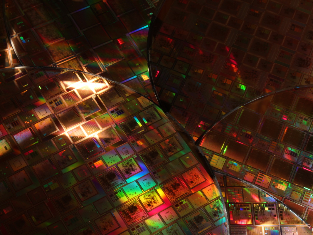
The Semitherm experiment examines the liquefaction properties and alloy structures of silicon and germanium in different conditions to compare alloys generated in space with those produced on Earth for application in semi-conductor fabrication. Finally, the Thermolab experiment will study an array of alloys that are already in use in industries on Earth. Information on the properties of the liquid alloy phase and its solidification characteristics could lead to better production processes at lower cost, higher speed and with less waste.
