DMC3 Satellite Constellation

DMC-3 stands for Disaster Monitoring Constellation 3 and represents three high-resolution optical Earth imaging spacecraft owned and operated by DMCii (DMC International Imaging), headquartered in Guildford, UK. The company is a subsidiary of Surrey Satellite Technology Ltd., the manufacturer of the three identical DMC-3 satellites flying in a 630-Kilometer Sun-Synchronous Orbit. SSTL is a world leader in small-satellite technology ranging from satellite components, bus platforms, payloads and complete satellites for operation in Earth imaging, technology demonstrations and a range of other of applications.
The business model of DMCii calls for the company operating the DMC satellites and leasing their capacity to commercial customers, providing daily access opportunities to any given area on Earth. The first customer to sign with DMCii was 21AT, the Twenty First Century Aerospace Technology Company Ltd. in Beijing, China. Signed in 2011, the contract includes the lease of the entire capacity of the first three DMC satellites with a contract time of seven-years.
resp links:
The entire DMC-3 constellation has been designed to meet 21AT’s Earth observation requirements of a one-meter ground resolution in the panchromatic and three-meter resolution in the multispectral bands. Under the contract, all satellite related tasks are executed by DMCii including observation scheduling and satellite operation while 21AT makes observation requests and receives processed data products.
The two companies have prior business experience through the Beijing-1 satellite that has been operated by SSTL since 2005 and was used to provide Earth observation products to 21AT and the Chinese government for environmental monitoring, resource management, agriculture, urban planning, disaster management and a number of other purposes.
DMCii expects the DMC-3 constellation to be a stepping stone to a larger constellation as more and more satellites can be added to respond to the demand for high-resolution Earth image data and value-added Earth Observations and GEO information services.
The company offers two ways of becoming part of the DMC project – satellite operators can contribute a satellite to the constellation and access data from all other constellation spacecraft or customers can lease capacity from the constellation. The first DMC mission was launched in 2002 based on the SSTL-100 satellite bus and operated by Algeria. Other participating nations in the DMC project include Turkey, Nigeria, Spain and the UK, all using SSTL-built satellites. Deploying a series of satellites allowed the DMC project to access different types of instrument data including high-resolution panchromatic imagery and medium-resolution multispectral data products with a radar capability planned in the coming years via the NovaSAR-S satellite.
Spacecraft Overview
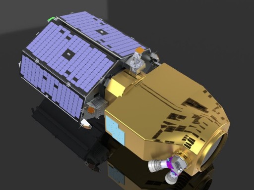
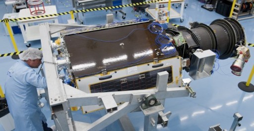
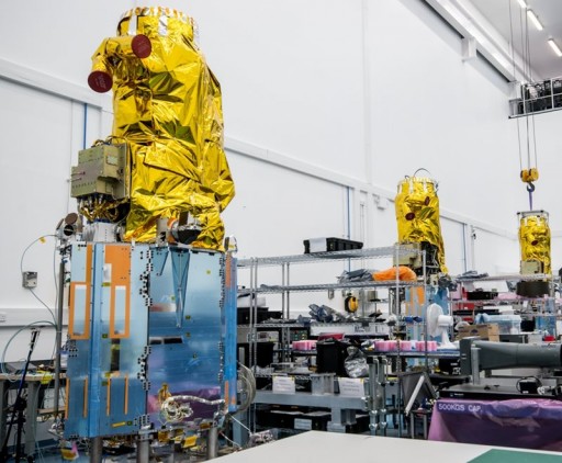
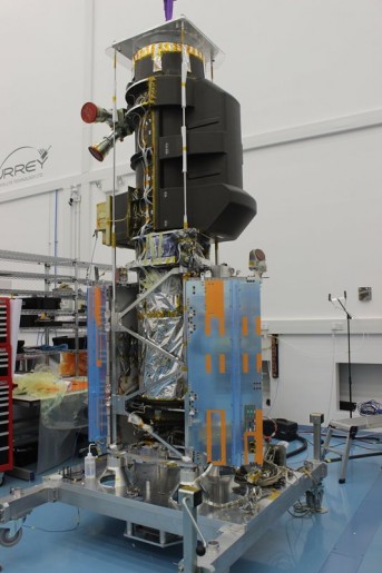
The three DMC-3 satellites are based on the SSTL-300 S1 spacecraft platform that builds on the smaller SSTL platforms such as the SSTL-100 and –150 using a number of heritage components in a larger, more-capable platform that can host imaging payloads achieving sub-meter resolution. Prior to DMC-3, SSTL-300 was flown by the NigeriaSat-2 satellite that met the planned requirements and showed an excellent performance after its 2011 launch. The S1 addition to the SSTL-300 bus represents a composite imager barrel that is part of the imaging payload, giving the satellite a length of over 2.5 meters.
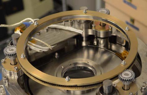
Weighing in at around 350 Kilograms, each DMC-3 spacecraft consists of two major components – a platform assembly hosting the various satellite subsystems and a 150-Kilogram payload assembly that facilitates the optical imaging system and the imager barrel. The core of the satellite structure is a cylinder that is comprised of several segments – beginning in the aft of the spacecraft with a Lower Link Assembly that interfaces with the launch vehicle adapter and a Lower Barrel that is connected to the Upper Barrel Assembly by a Central Bulkhead which can provide mounting structures for various systems including payload structures. The Upper Barrel Assembly consists of laminated pre-impregnated Carbon Fiber Reinforced Polymer (CFRP) with several circumferential L-profile CRFP ring cleats and titanium fittings that provide the attachment points for the payload hardware.
The Central Bulkhead is responsible for the structural connection between the payload and the satellite platform in addition to load transfer during launch and dampening of vibrations originating within the satellite platform systems. The bulkhead includes two bearing assemblies of two- and three-degree of freedom configurations. It consists of similar materials as the Upper Barrel, but given the more significant loads of the bulkhead, its structural components are of increased thickness. The Lower Barrel resembles the Upper Barrel in appearance, but is shorter and uses less-thick material.
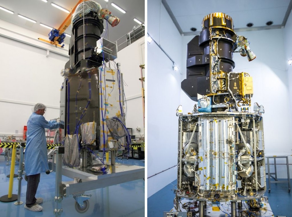
DMC3 Imager Barrel
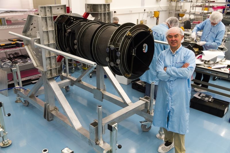
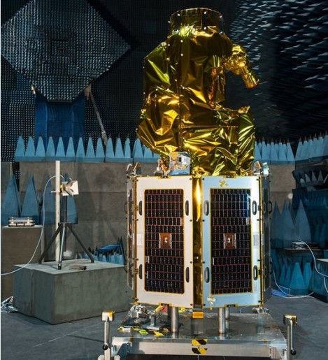
DMC-3 consists of a seven-faced spacecraft body assembly that facilitates the satellite platform systems that are joined with the optical payload system featuring a large imager barrel, also hosting star trackers and other external equipment. The satellite platform has a mass of around 218 Kilograms and includes all systems needed for electrical power generation and distribution, attitude determination and control, propulsion, data and command handling, and thermal control.
The SSTL-300 satellite bus generates power through the use of body-mounted solar panels on all seven satellite platform faces creating an area of 2.44 square meters. The triple junction Gallium-Arsenide solar cells deliver power to dedicated avionics that control the state of charge of a 15-Amp-hour battery assembly and condition a main power bus that operates at 28 to 33 Volts. Available payload power at the end of the satellite’s life is projected to be around 140 Watts with peaks at 180W.
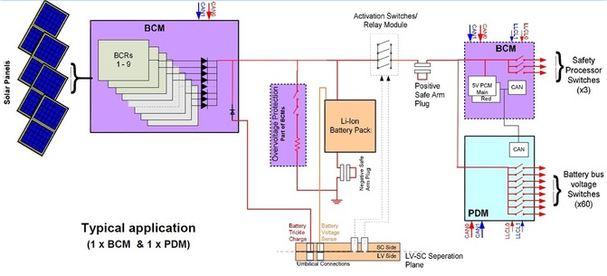
The Power Conditioning and Distribution Unit installed on the satellite consists of a 2.6kg Battery Control Module and a 1.8kg Power Distribution Unit – each measuring 33.5 by 30.5 by 3.9 centimeters in size. It is rated for a 7.5-year life in Low Earth Orbit and is capable of accepting the raw power supply from the solar panels and conditioning a regulated power bus that is then distributed to the satellite systems and the Flight Battery System. The PDM delivers latching current limited or fuse protected power via 60 latching current limited power distribution switches from 0-2.5 to 0-7.5A.
Electrical Power System Schematic
The thermal control system of the DMC-3 satellites uses mostly passive systems in the form of Multilayer Insulation that protects the various satellite subsystems. Aluminum panels used aboard the satellite can dissipate some excess heat when needed and a heater system ensures that all satellite components are kept in an acceptable thermal environment at all times. The Flight Battery is the component that requires the tightest thermal control that is accomplished with heater mats and temperature sensors.
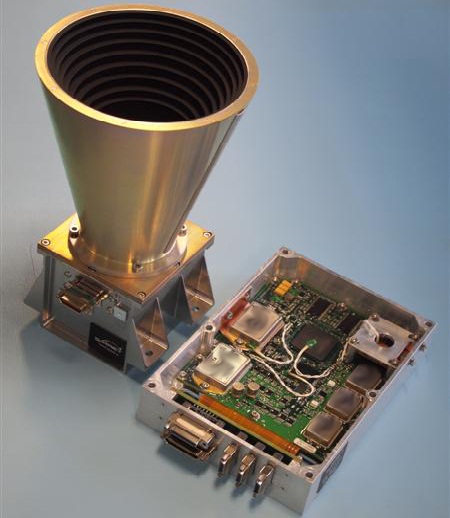
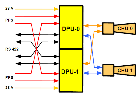
The Attitude Determination and Control System of the DMC-3 Satellites uses a redundant set of sun sensors and magnetometers for coarse attitude knowledge and new Procyon star tackers for high-precision three-axis orientation knowledge. Procyon uses two optical heads and two Data Processing Units with cross-strapping between the two strings for a high degree of redundancy. The optical heads use 60-degree baffles and are 9 by 11 by 11 centimeters in size plus the 14 by 16cm baffle. Procyon uses Active Pixel Sensors to achieve a field of view of 15 by 15 degrees and operates at an update rate of up to 4 Hz.
The DPU is 15.5 by 21 by 5.6 centimeters in size weighing under 1.2 Kilograms while the optical head weighs 1.0 Kilogram. The system can acquire three-axis attitude data within eight seconds from power-on with an accuracy of 5 arcsec on X/Y and 50 arcsec on Z. The star trackers are integrated into the spacecraft data system via an CAN-SU or RS-422 bus. Procyon can recover from a lost in space mode, meaning that the star trackers can deliver attitude solutions without any prior attitude knowledge. The star tracker tolerates angular rates of 2°/s and accelerations of 1°/s².
Star Tracker System
The Attitude Actuation System of the DMC-3 satellites uses a set of four SSTL-100SP-O reaction wheels plus four 200SP-M momentum wheels that give the spacecraft a high degree of agility.
Four reaction wheels are in use for redundant attitude control about the three axes, tolerating the loss of one reaction wheel without degradation of satellite attitude control capabilities. The reaction wheel assembly is a rotating inertial mass that is driven by a brushless DC motor that spins the wheel.
When accelerating the wheel, the satellite body to which the wheels are directly attached will rotate to the opposite direction as a result of the introduced counter torque. The 100SP-O wheels have been chosen to give the satellite a high agility and high pointing precision given the requirements for image acquisition accuracy. The wheels were optimized to provide a favorable micro-vibration environment that was verified through extensive ground testing.
The 100SP-O reaction wheels are 13.1 centimeters in diameter and 12cm tall with a mass of 2.6 Kilograms. They are rated for 7.5 years of LEO operation and support a broad thermal environment. The RWA uses oil-lubrication and can deliver a maximum torque of 110mNm which corresponds to a peak power demand of 113 Watts at max. torque. In standby mode, the wheels require 1.2W of power and the on-orbit average is around 10W. The wheels spin at up to 5,000RPM, limited by micro-vibration requirements.
The 200SP-M momentum wheels measure 24 centimeters in diameter and are 9cm tall with a mass of 5.2 Kilograms. Spinning at up to 5,000RPM, the momentum wheels can generate a peak torque of 240mNm. The system requires an average power of 16 Watts with a peak at max torque around 145W.
Three Magnetotorquers MRT-30 are used for momentum management on the satellite and for attitude control in spacecraft safe mode. Magnetic Torque Rods create angular momentum by running a current through coils in the presence of Earth’s magnetic field. The torquers are regulated by computers that control the current that is passing through the coils in order to control the force generated on each axis. The magnetic torquers are used during momentum dumps and for attitude control in spacecraft safe mode. Actuation of the torquers is commanded based on readings from a three-axis magnetometer. The MTR-30 system operates at voltages greater than 5V to create a magnetic moment of up to 30Am². MTR-30 weighs 1.8 Kilograms and measures 37.8 by 7.4 by 4.9 centimeters in size. The Magnetometer Package has an operational range of +/-60 milli-Tesla with a sensitivity of +/-10 Nano-Tesla. The Magnetometers measure 3.6 by 9 by 13 centimeters in size with a mass of 190 grams.
All in all, DMC-3’s Attitude Determination and Control System reaches a pointing knowledge of 72arcsec, a pointing accuracy of 360 arcsec and a pointing stability of 2arcsec per second. The DMC-3 spacecraft can support fast slew rates that enable +/-45° pointing of the imaging system within a period of a minute.
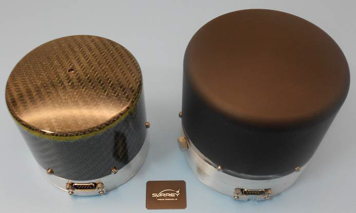
Momentum Wheel & Magnetic Torquer
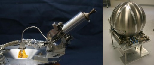
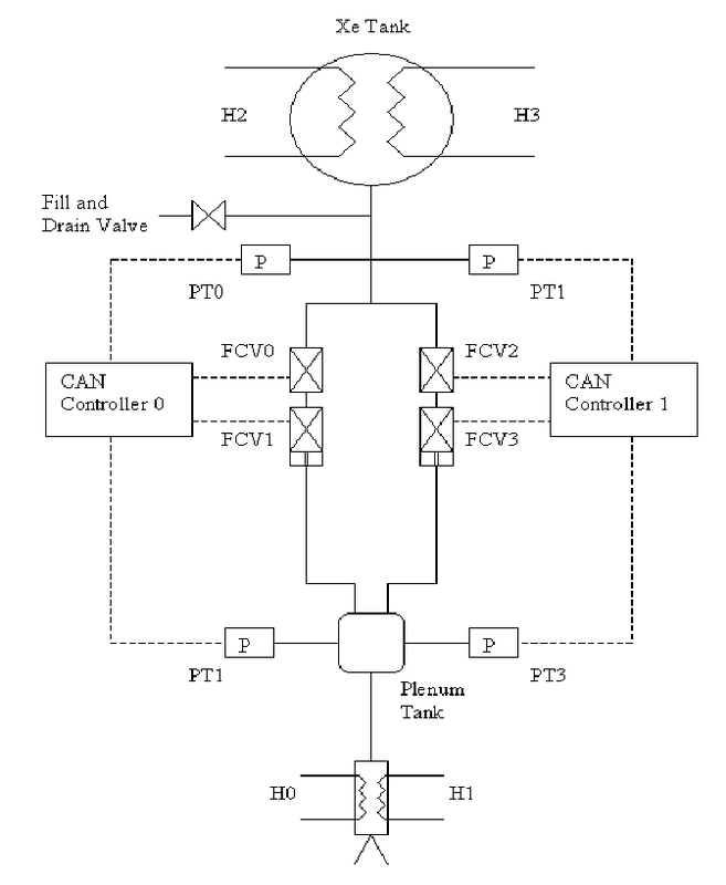
The DMC-3 satellites host a Hot-Gas Xenon Resistojet as a Main Propulsion System with a total delta-v budget of 15m/s in support of orbit corrections after launch, constellation maintenance and orbital maintenance for the minimum mission duration. The system consists of a Xenon tank and resistojet thrusters that delivers a thrust of 10 to 100 Millinewtons operating in blow-down mode with an average impulse of 48 seconds. The 7.4-liter tank can hold up to 12kg of Xenon at a pressure of 70 bar. Propulsion will be used for orbit adjustments and drag make-up maneuvers. Overall, the propulsion system weighs 19.4 Kilograms and is 23 by 30 by 30 centimeters in dimensions.
Coarse Attitude Determination is provided by a suite of sun sensors with a field of view of +/-50 degrees and an accuracy of 1° that allows the satellite to enter a sun-pointing attitude in case of an S/C safe mode event. The sun sensors measure 9.5 by 10.7 by 3.5 centimeters in size and weigh 210 grams. Orbit Determination and position determination is accomplished through GPS, DMC-3 hosts an SGR GPS receiver and reaches a position accuracy of 10 meters. The GPS terminal also provides precise timing solutions that are used across the satellite.
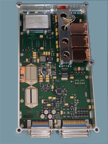
The satellite uses an OBC750 onboard computer that is based on a BM PPC750FL processor. The OBC system is in charge of receiving and processing commands from Earth and controlling all satellite subsystems. The system also receives all payload data that is stored and conditioned for downlink by the OBC.
The computer has a memory of 6MB EEPROM (boot software), 256MB EADS, 16MB MRAM and 16MB Flash. It supports the 1553B high-speed data bus as well as two dual CAN buses, eight LVDS inputs and outputs, four opto isolated inputs and four opto isolated outputs. The OBC measures 32 by 32 by 6 centimeters and weighs under 2.5 Kilograms requiring 20 Watts of power during operation and 3W in standby.
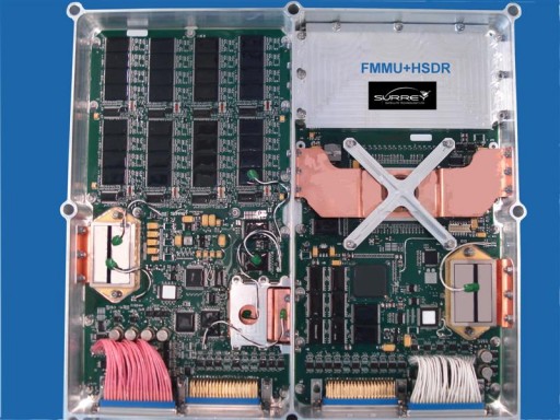
A mass memory with 128GB of non-volatile memory is hosted by the DMC-3 satellites, combining the capabilities of the High Speed Data Recorder and Flash Mass Memory Unit in charge of onboard data acquisition, storage and playback. The system is of a modular architecture that can allow memory to be added based on mission requirements. Internally, the mass memory uses a 16GB tightly coupled memory and 128 GB of mass memory, running a 1Gb/s internal data link.
The system uses DDR2 and flash technologies to be able to handle the high data rate payload data and accommodate the relatively low rate of the flash memory. The Mass Memory Unit measures 31 by 31 by 6 centimeters in size and weighs under 2.5 Kilograms. Using HSDR heritage, the system can support 20 LVDS inputs/outputs at a data rate of 150Mbps, 5 SerDes inputs at up to 2Gbps and 16 LVDS outputs at 150Mbps.
DMC-3 handles all command uplinks and spacecraft telemetry data downlink via S-Band, hosting a 4-Watt RF Power S-Band Transmitter and a dedicated receiver. The S-Band transmitter can deliver data at rates from 9.6kbps to 8.0Mbps using BPSK or QPSK modulation, accepting data via LVDS. For command uplink, DMC-3 uses an S-Band receiver operating at a frequency between 2025 and 2110 MHz reaching data rates of 9.6 or 19.2 kbps.
For the downlink of Earth Observation data, DMC-3 relies on an improved version of SSTL’s X-Band High-Data Rate Communications System that consists of a powerful transmitter system and a two-axis gimbaled antenna that can track ground stations regardless of satellite attitude to maximize the amount of data that can be returned to Earth.
Changes made to the X-Band system that initially supported a data rate of 400Mbit/s include the implementation of a more powerful Field Programmable Gate Array within the modulator module to be able to handle greater data rates and higher order modulation. In a second upgrade, the transmit output was increased to 12 Watts using a next generation transmitter.
The system uses a circularly polarized horn antenna with a narrow-beam width and boresight requiring a high pointing accuracy of one degree. The system supports maximum slew rates of 20deg/s and is capable of focusing the radio frequency output into a high-gain spot-beam that is steered to track the position of the ground station by moving the antenna +/-114.7 degrees in elevation and +/-270 degrees in azimuth.
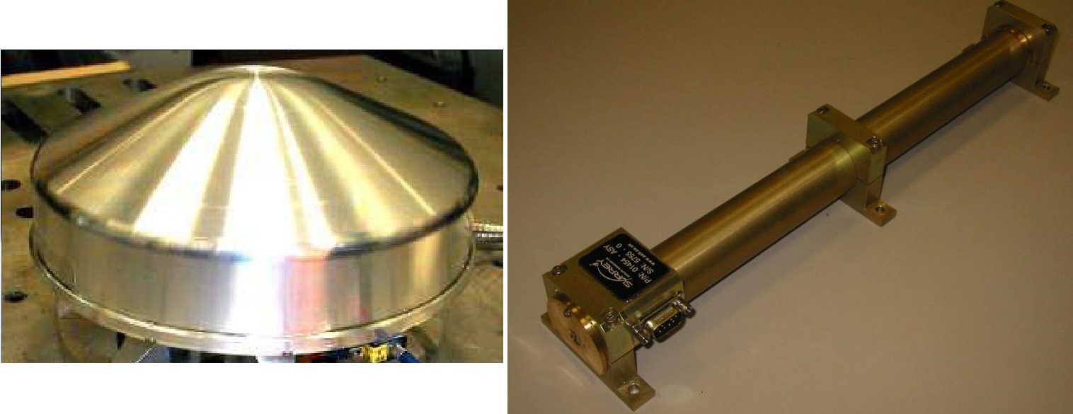
Antenna Pointing Mechanism
S1 Instrument Overview

All three DMC3 satellites carry an identical payload module known as the S1 Imager, also referred to as VHRI 100, Very High Resolution Imager 100. The instrument builds on the 2.5-meter resolution imager flown on the NigeriaSat-2 mission. S1 is capable of multispectral imaging in the visible and infrared wavelengths using a modified Newtonian telescope which provides the best optical imaging quality within the limitations of a small satellite bus. The instrument achieves a resolution of one meter in the panchromatic band and a multispectral resolution of four meters.
As with all space-based imaging systems, thermal stability was a leading driver in the design of the system. To ensure all optical components remain in a precise alignment, low expansion materials are used wherever possible across the entire payload assembly. Carbon fiber composites make up the telescope structure, the optics consist of Zerodur and fused silica and low-expansion alloys are used for the optical mounts.
The focal plane assembly consists of long linear Charge Coupled Device arrays employing in-field separation to avoid the more complex design featuring beam splitters in the focal plane.
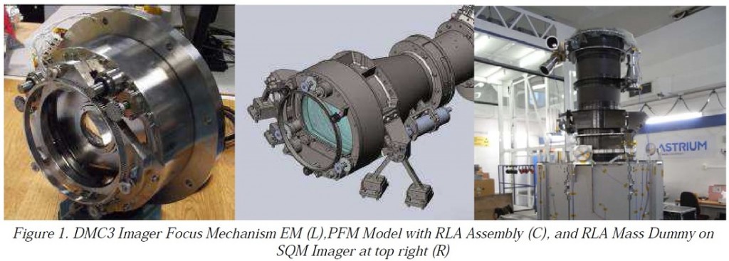
Focus control within the telescope is provided by a moving corrector lens that is located near the center of the primary mirror. Given the more stringent requirements of the S1 payloads in terms of focus lens alignment, linear position and stability, the old design employed by NigeriaSat was no longer viable and a completely new system was developed, referred to as Relay Lens Assembly.
The overall purpose of the RLA is the placement of the focusing lens along the optical axis to ensure the Earth image is focused with the specific depth of focus of the focal plane. To achieve the required image quality, the Relay Lens Assembly has to be capable of placing the focusing lens with an accuracy better than 5 micrometers along a travel distance of 10 millimeters. The lens has to provide an extremely high positional stability in the various environments of launch, thermoelastic loads and the micro-vibration environment on the satellite. The parallel shift of the lens optical axis has to be less than 5 micrometers and the tilt of the lens against the telescope’s optical axis can be no greater than 15arcsec. Optical decentration can be no greater than 10 micrometers.
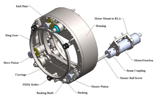
The focusing lens is 14.8 centimeters in diameter and utilizes a stepper motor, and stainless steel ball screw to drive the lens carriage along the three linear ball bushing shafts. The lens is truncated at two sides with a width of 11 centimeters and it resides within a titanium lens cell which is bonded into place on the titanium lens carriage mechanism. A non-contacting linear decoder provides independent feedback of the motion and position of the focusing lens.
The S1 instrument uses five linear detector arrays separated in the along track direction within the common focal plane of the telescope keeping with a pushbroom-type design that images the ground area as it passes the different arrays. Time Delayed Integration is employed for the read-out of the detectors that have an excellent Signal to Noise ratio of 100:1 so that imaging of low-albedo targets poses no challenge to the S1 instrument.
The instrument covers five spectral bands – a panchromatic band at 450 to 650 nanometers achieving a one-meter ground resolution and four multispectral bands with a four-meter resolution: 440-510nm (blue), 510-590nm (green), 600-670nm (red), and 760-910nm (near infrared).
From its orbit, DMC-3 can observe a ground swath with a width of 23 Kilometers. The maximum swath length is limited by onboard data constraints and is about 4,000 Kilometers. 21AT will primarily use the satellites for imaging of the Chinese Territory with high revisit times.
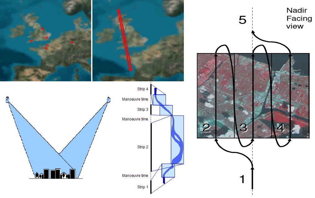
DMC-3 supports a number of different imaging modes. In scene mode, the instrument delivers 23 by 23 Kilometer images in all five spectral bands. Scenes can be targeted within the roll capability of the satellite. Owing to the high agility of the spacecraft, scenes that are separated in the cross-track direction but not the along-track direction can still be imaged on a single pass.
Strip mode delivers long strips of images in the nadir-pointing direction. This mode is primarily used for applications such as mapping and systematic mosaic imaging to deliver complete maps of certain areas, territories and countries. Maximum strip length is 175 scenes.
Stereo imaging can be supported by the satellite on a single pass – requiring the spacecraft to acquire an image of the same ground area from two different view angles so that ground processing algorithms can combine the images to deliver height information on a given target. The angle at which the image pair is acquired can be varied for different applications.
A more complex imaging mode is the Area Mode in which the satellite conducts roll and pitch maneuvers to artificially widen the swath width by obtaining images of adjacent scenes. The standard form of single-pass area imaging to be employed by DMC-3 would be a 2×2 observation of a 40 by 45-Kilometer zone. Earlier information also indicated that 3×3 single-pass area imaging would be possible using the vehicle’s fast response system.
It is anticipated that the DMC-3 constellation will be able to image a ground area of 1 million square Kilometers each day.
Available Imaging Modes