
DeOrbitSail
DeOrbitSail is a NanoSatellite mission aiming to conduct an end-to-end demonstration of a satellite deorbiting sail for potential future application in space missions to reduce the growing orbital debris problem by rapidly removing satellites from orbit after the end of their operational missions.
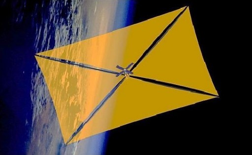
The test mission uses a 3-Unit CubeSat to deploy a large five-by-five-meter ultra-thin sail to increase the drag acting on the spacecraft, resulting in quicker orbital decay. The goal of the mission is to demonstrate the deployment system of the sail and the performance of the system in terms of acceleration of decay.
Although humans have only been flying to space for six decades, the problem of space junk has come to a point where changes have to be made. Old practice was to abandon satellites in orbit once their mission was finished, leaving hundreds of defunct and uncontrollable spacecraft in orbit around Earth, plus thousands of pieces of smaller fragments that are the result of satellite explosions, collisions or other debris-generating events. These debris pose a serious risk to active satellites, and satellite operates frequently have to perform Debris Avoidance Maneuvers to move their spacecraft out of the way of debris. The more debris and dead satellites are in orbit, the higher the risk of collisions which leave large amounts of debris in orbit as previous cases have shown.
Orbital debris mitigation guidelines have been debated in great detail over the past decade and a number of recommendations have been made that are being followed by most operators – such as a 25-year deorbit requirement for a satellite operated in Low Earth Orbit. Technologies such as drag sails could be used to speed up the orbital decay of satellites in order to comply with the 25-year guideline or remove satellites from orbit even faster. However, such a deorbit system would have to be very low in mass and high in reliability since space missions always face compromises between mass & capability.
To tackle the problem of developing a deorbit-sail system for potential future use on LEO satellites, a consortium of ten institutions joined forces as part of the DeOrbitSail Project (DOS). These include institutions from the United Kingdom, the United States, Germany, France, South Africa, Greece, Turkey and The Netherlands. Each institution is responsible for the development and testing of one particular system while the overall project is being managed by the Surrey Space Center, UK.
With a budget of 2.8 million Euros, the project outlined a number of objectives including the development of a sail system capable of flying on a 3U CubeSat bus and extending to a total surface area of 25 square meters. The mission requirements also call for an active attitude control system to adjust the orientation of the sail to test both, acceleration/deceleration through solar pressure, and the use of increased drag for deorbitation. The mission is expected to last for at least one year during which solar force & drag data will be gathered.
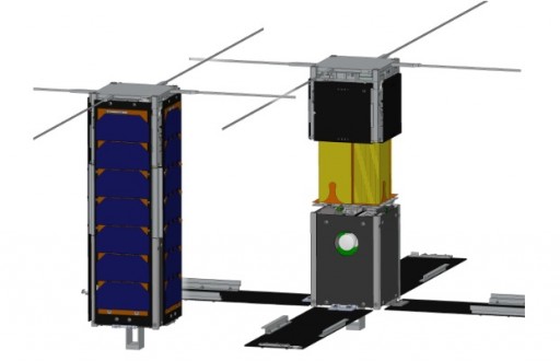
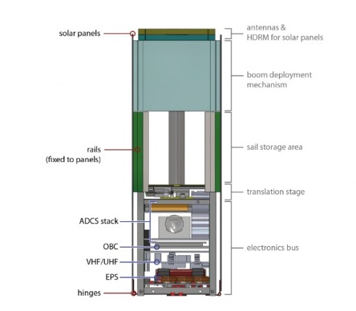
DeOrbitSail uses the conventional 3-Unit CubeSat form factor, measuring 10 by 10 by 34 centimeters in size with a mass of under six Kilograms. The 1U Section in the aft of the satellite is used to facilitate the spacecraft systems while the forward 2U section hosts the payload comprised of the densely packed sail and its deployment mechanism.
Electrical power is generated by four deployable solar panels that are hinged on the aft side of the satellite and stowed against the long sides of the satellite body for launch, covering up the sail section.
When in their launch position, the solar panels can deliver power even in case of an initial tumble about all three axes. After deployment, the satellite needs to be under attitude control to properly point the panels toward the sun as all panels are facing a single direction when in their deployed position. Each of these panels hosts six solar cells that deliver power to a power distribution system that controls the state of charge of the onboard batteries and distributes power to all users on the spacecraft.
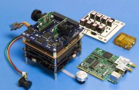
The DOS satellite hosts an active Attitude Determination and Control System that takes up the majority of space within the electronics stack of the spacecraft. A series of sensors are used to determine the satellite’s orientation and body rates including Earth and Sun sensors used to provide pointing data as well as cameras plus gyroscopes that can be used to determine the satellite’s geometry relative to Earth. Coarse determination of the sun vector is possible through the use of six photodiodes, one on each spacecraft panel to allow the onboard computer to determine which side of the satellite is facing the sun. Optical sun and nadir sensors are used for a more accurate determination of the Earth and Sun positions. A three-axis magnetometer is installed on a small stand-off bracket on the aft side of the spacecraft to deliver precise measurements of Earth’s magnetic field for the generation of attitude actuation commands. The DOS spacecraft employs a three-axis MEMS-gyro for precise body rate measurements.
The primary systems for attitude actuation are three magnetic torquers and a single momentum wheel.
resp links:
Magnetic Torque Rods create angular momentum by running a current through coils in the presence of Earth’s magnetic field. The torquers are regulated by computers that control the current that is passing through the coils in order to control the force generated on each axis. The single momentum wheel is mounted to be able to provide precise attitude control along the pitch axis to properly point the sail once deployed.
The Deorbitsail spacecraft uses a number of Commercial Off-The-Shelf components such as its onboard computer and communications system. The Onboard Computer is in charge of all satellite tasks – commanding the various subsystems, running the Attitude Determination and Control algorithms, storing telemetry and payload data, receiving and executing commands from the ground and processing data prior to transmission for downlink. A conventional VHF/UHF antenna and radio system is used by the spacecraft for command uplink and data downlink.
The Deorbitsail spacecraft is released from an ISIPOD (Innovative Solutions In Space BV. Pico Orbital Deployer) and will initially enter a tumbling motion while awaiting the first ground station pass for the uplink of initial instructions. De-tumbling will be performed after body rates can be accurately determined from the six coarse sun sensors and the magnetometer. Initially, the satellite will enter a Y-Thompson spin before solar panel deployment takes place and the satellite attitude control system is transitioned to stable three-axis pointing.
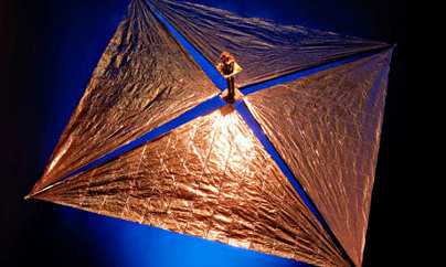
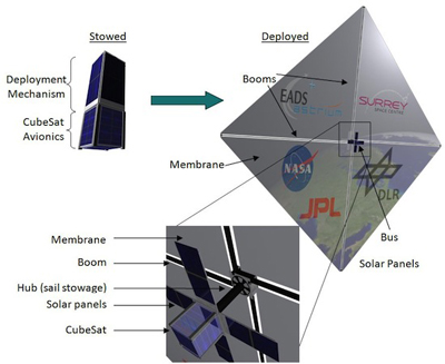
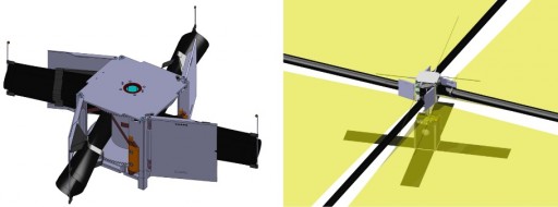
The drag sail of the DOS spacecraft consists of four triangular segments deployed from four wedge-shaped compartments of the satellite. When fully deployed, the sail measures five by five meters in size giving it a total surface area of 25 square meters. The quadrants are deployed and tensioned by four diagonal deployable masts that draw the sail out to its fully deployed configuration when deployment is commanded.
The closed-section booms consist of carbon-fiber material and are flattened before being coiled up around a central hub. For deployment, the coils are unwound by a motor that winds up thin metal strips co-coiled with the booms so that the boom coil is rotated and the booms extend outward, pulling out the sail.
resp links:
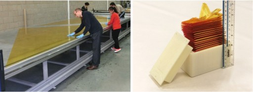
The sail itself consists of a 12.5-micrometer thick aluminized Kapton membrane. Initially a non-aluminized semi-translucent Kapton materialwas chosen to reduce the occlusion of the solar arrays and attitude determination sensors and minimize interference with the radio system. However, after testing, this material was substituted by the more conventional aluminized Kapton after the original material had shown electrostatic build-up that led to adhesion during deployment and degraded deployment results. The sail is kept at tension by a constant-force spring that is located on the central connection point
In the stowed configuration, each sail quadrant is packaged to a size of 9.3 by 5 by 3.7 centimeters using a Z-Folding Technique. The first fold lines are parallel to the hypothenuse of the triangular sail section at a spacing of 88 millimeters while the second set of folds is perpendicular at 49-millimeter intervals. The manufacture of one sail segment required approximately three days of work by a team of three people.
When the sail has been deployed – which will be as early as possible in the mission – a black-and-white camera equipped with a fish-eye lens will acquire a photo of around half the sail area to provide a visual confirmation of the deployment an the tension status. For the first two to three weeks after deployment, the pitch angle of the solar sail will be modified to demonstrate solar sailing, using solar pressure interaction with the sail to generate a minute force of thrust. Solar sailing will be demonstrated by measuring the thrust force with the satellite’s attitude determination system and measuring its orbit.
After the solar sailing demonstration, the orientation of the satellite will be changed to point the sail into the ram direction to maximize drag on the satellite to accelerate orbital decay. The efficiency of the sail will be measured through data from the satellite as well as orbital tracking. A full mission success will be declared if orbital data shows the expected rapid decay of the satellite, leading up to destructive re-entry.
