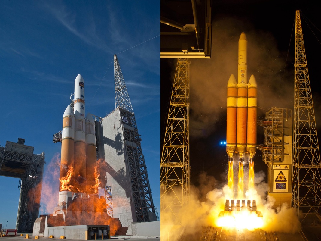
Delta IV Heavy
This version of the Delta IV is retired, please refer to the Delta IV Heavy (RS-68A) Page for details on the current vehicle.
The Delta IV Heavy is one of various versions of the workhorse launcher family of Delta IV Evolved Expendable Launch Vehicles. In the family of Delta IV rockets, the DIV Heavy is the most powerful launcher and, since the retirement of the Space Shuttle has been the most powerful launcher available in the United States, a role it will maintain until SpaceX introduces its Falcon Heavy booster.
The Delta family has a storied history with the original Delta making its first launch in 1960. Over the years, several generations of Delta launch vehicles have been flown – currently, the Delta II and IV rocket families remain in operation. Delta IV is built by Boeing, operated by United Launch Alliance for commercial launches, military missions as well as NASA Flights.
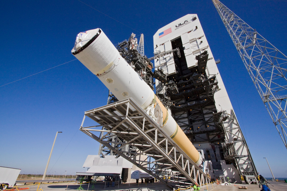
Delta IV rockets are operated from Space Launch Complex 37 at Cape Canaveral Air Force Station, Florida, and Space Launch Complex 6 at Vandenberg Air Force Base, California.
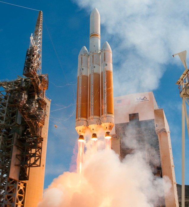
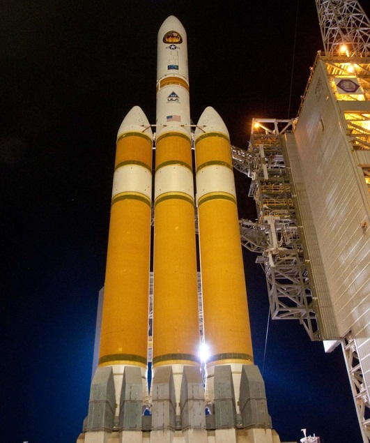
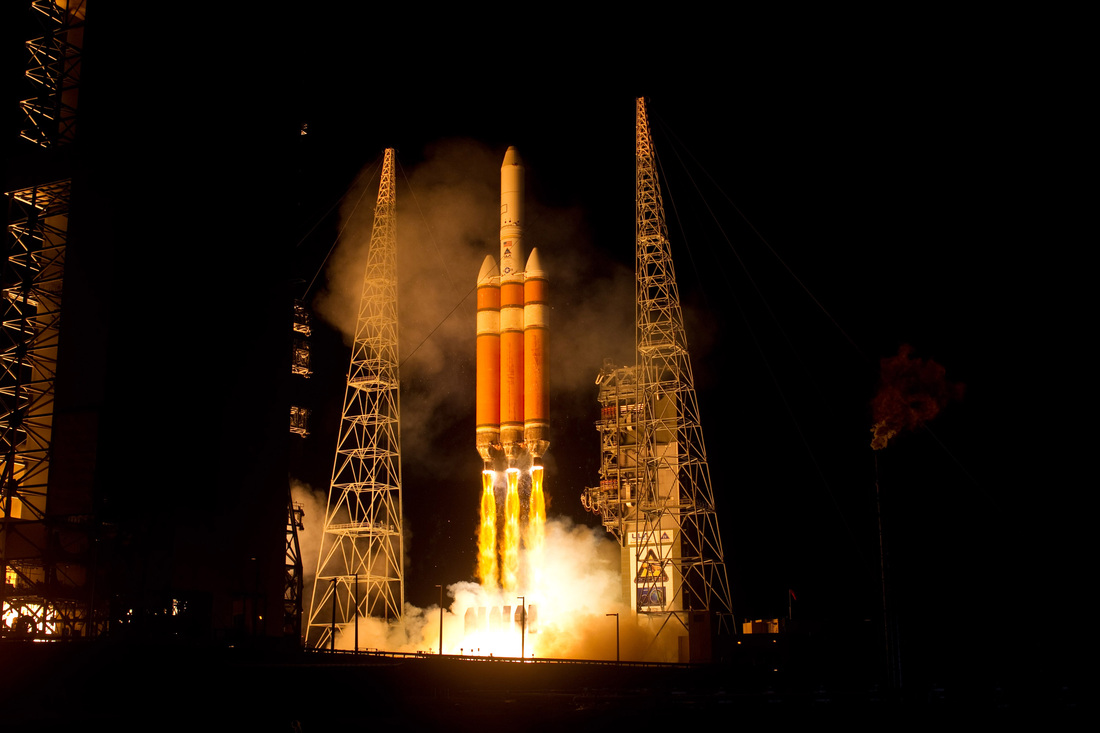
As one of the most powerful launch vehicles in the world, Delta IV heavy has a launch mass of 733 metric tons and can deliver payloads of 23 metric tons into orbit. The vehicle is comprised of a Common Booster Core as a central core stage with two additional CBCs attached to the core to deliver extra thrust in the early portion of the flight. Not employing propellant cross-feed, the two boosters fire at full throttle during their burn while the core saves propellants by throttling back shortly after launch to continue burning for another 90 seconds after strap-on separation.
Introduced in 2013, all Delta IV vehicles will transition to a more powerful version of the RS-68 cryogenic first stage engine known as RS-68A as soon as all existing RS-68 engines have been flown.
The Delta IV Heavy features the larger Delta Upper Stage with a 5-meter diameter and larger propellant tanks. The vehicle is outfitted with 5-meter payload fairings to accommodate large payloads. Delta IV is capable of delivering payloads to a variety of orbits such as Low Earth Orbit, Geostationary Transfer Orbit and Geostationary Orbit as well as interplanetary trajectories.
The entire Delta family makes use of flight proven components and proven design concepts to improve Launcher Success Rate. Delta IV Heavy has made seven launches to date (Nov. 2014). The maiden voyage of Delta IV Heavy in December 2004 was cataloged as a partial failure as all three CBCs suffered a premature cutoff during the launch sequence. The remaining launches were successful.
Other Delta IV Configurations: Delta Medium, M+ (4,2), M+(5,4), M+(5,2)
Delta IV Heavy Specifications
| Type | Delta IV Heavy |
| Height | 70.7m |
| Diameter | 5m |
| Span | 15.00m |
| Launch Mass | 733,400kg |
| Stage 1 | Common Booster Core |
| Boosters | 2 Common Booster Cores |
| Stage 2 | 5-Meter DCSS |
| Mass to LEO | 22,950kg |
| Mass to GTO | 13,130kg |
| Mass to GEO | 6,275kg |
| Escape Capability | 9,306kg |
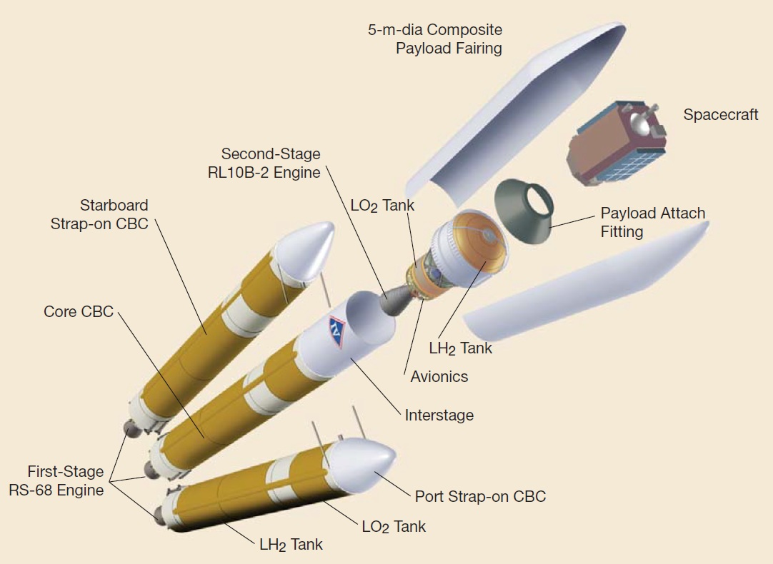
The Delta IV Heavy Version consists of a Common Core Booster with two strap-on CBCs functioning as boosters attached to it, a 5-meter second stage and a 5-meter Payload Fairing. Each CBC uses a single RS-68 engine consuming cryogenic propellants, Liquid Oxygen and Liquid Hydrogen. Using the larger version of the Delta Cryogenic Second Stage, Delta IV Heavy sports a single RL-10B engine on its upper stage.
The Launcher stands 70.7 meters tall, has a main diameter of 5 meters and a liftoff mass of 733,400 Kilograms. With its three CBCs, the rocket has a span at its base of over 15 meters.
Delta IV Heavy rockets using the conventional RS-68 engines can lift payloads of up to 22,950 Kilograms to Low Earth Orbit. Geostationary Transfer Capability is 13,130 Kilograms, the vehicle can lift 6,275 directly to Geostationary Orbit and send payloads of up to 9,306 Kilograms to interplanetary trajectories. A typical Delta IV Mission has a duration of 2.3 hours, but can be extended to 7 hours for specific mission profiles.
Common Booster Core
| Type | Common Booster Core |
| Inert Mass | 26,400kg |
| Launch Mass | 228,400kg |
| Diameter | 5.1m |
| Length | 40.8m |
| Propellant | Liquid Hydrogen |
| Oxidizer | Liquid Oxygen |
| Fuel&Oxidizer Mass | 202,000kg |
| Tank Structure | Al-Isogrid, Separate Bulkheads |
| LOX Tank Length | 9.4m |
| LH2 Tank Length | 26.3m |
| LOX Mass / Volume | 172,500kg / 151m³ |
| LH2 Mass / Volume | 29,500kg / 416m³ |
| Tank Pressurization | Gasified Propellants |
| Guidance | From 2nd stage |
| Propulsion | 1 RS-68A |
| Cycle | Open Cycle, Gas Generator |
| Thrust (SL) | 3,137kN |
| Thrust (Vacuum) | 3,560kN |
| Chamber Pressure | >196bar |
| Engine Length | 5.20m |
| Engine Diameter | 2.43m |
| Engine Dry Weight | 6,747kg (RS-68) |
| ISP (Vacuum) | 414s |
| Mixture Ratio | 5.97 |
| Nozzle Ratio | 21.5 |
| Throttle Capability | 57.5%-108% |
| Pitch, Yaw Control | Engine Thrust Vector Control |
| Roll Control | Vectoring of GG Exhaust Nozzle |
| Restart Capability | No |
| Burn Time | 328sec |
| Stage Separation | Pyro bolts, Springs |
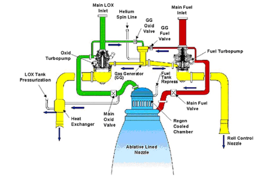
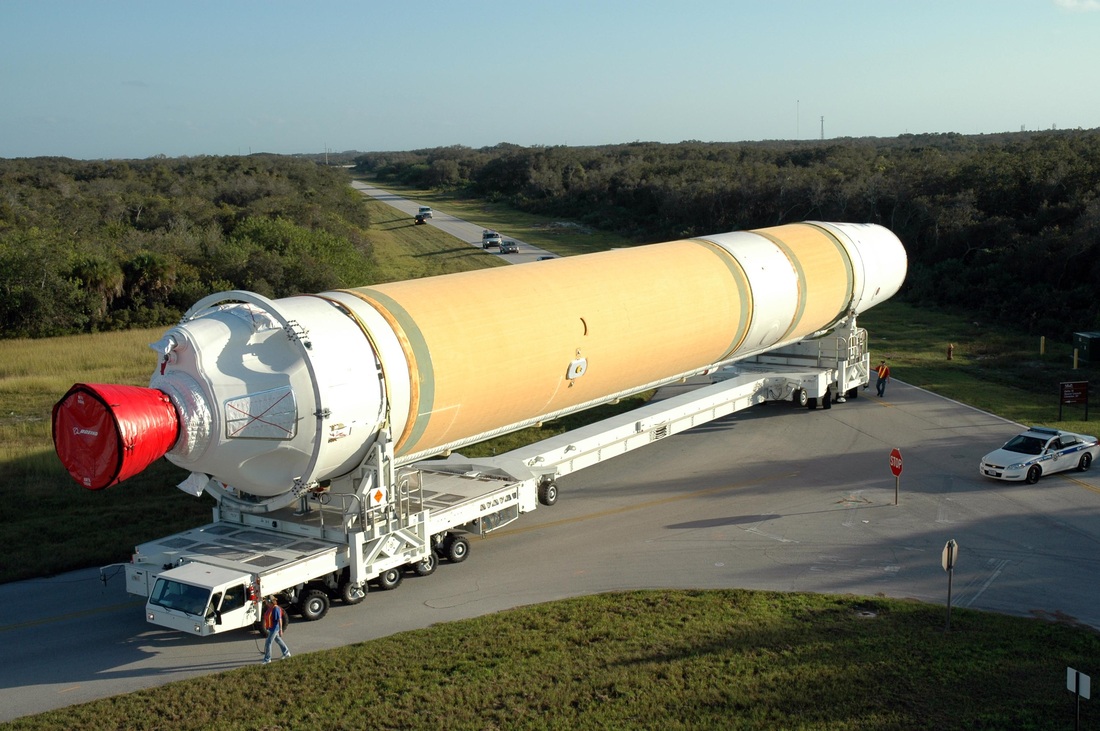
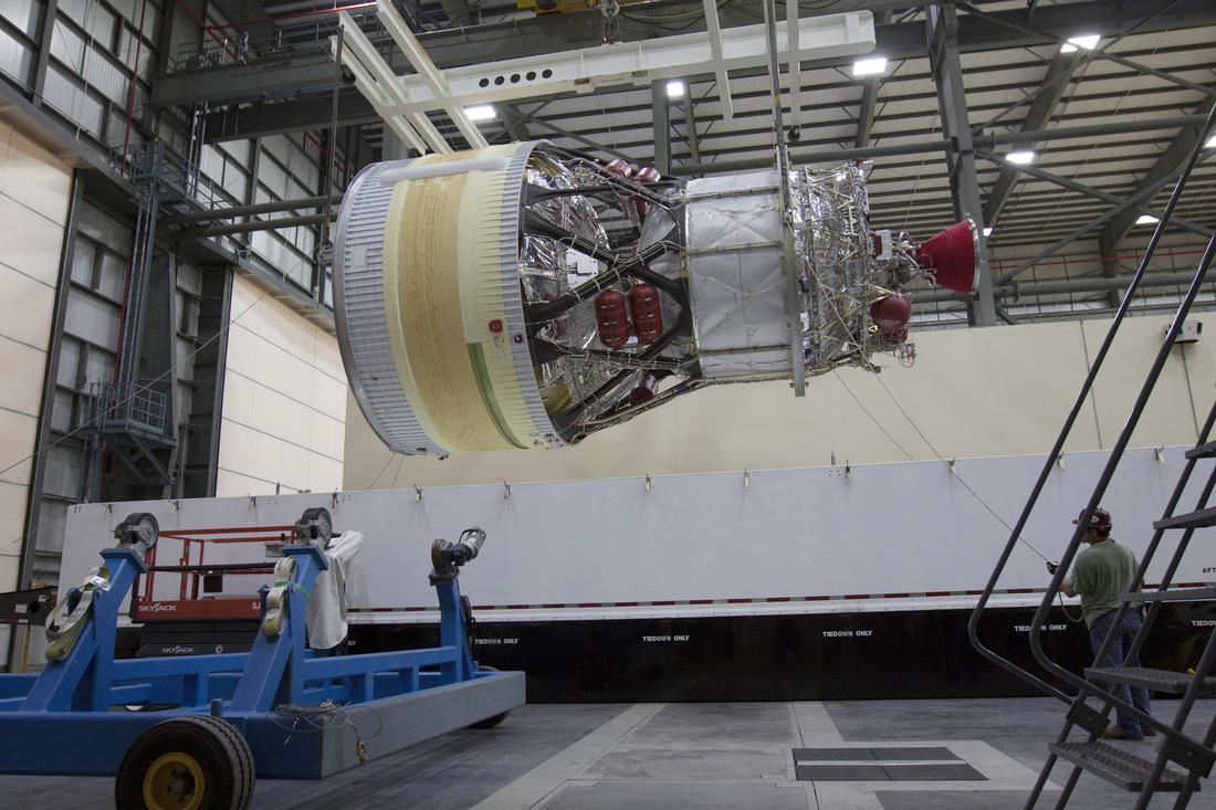
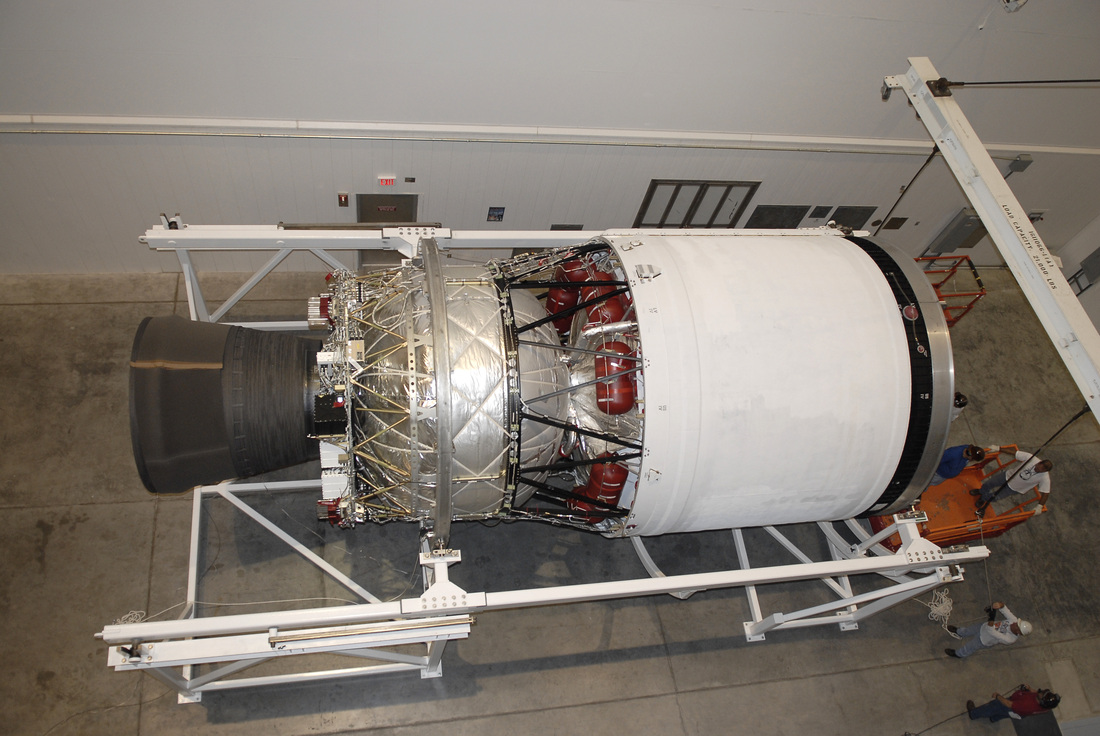
The Delta IV Heavy uses a Common Booster Core as its first stage. This booster, like its name says, is common across all variants of the Delta IV launcher family. The Common Booster Core consists of a Main Engine Compartment, facilitating the RS-68A powerplant, a Liquid Hydrogen Tank, an Intertank Section, a Liquid Oxygen Tank and an interstage section that builds the interface with the Delta Cryogenic Upper Stage.
Both propellant tanks use an aluminum-isogrid structure with five isogrid structures welded together to make up the cylindrical section of the tanks. At both ends, the cylindrical tank section is welded to a bulkhead structure. Delta IV’s CBC employs separate spherical bulkheads on the LH2 and LOX tanks. The tanks employ internal stringers for additional stability and the LOX tanks use anti-slosh baffles. The load-carrying external shell of the Common Booster Core is covered in rigid spray-on polyurethane foam for insulation and to prevent ice-build up around the cold cryogenic tanks. An external wiring tunnel runs down the length of the entire booster.
Sitting atop the LH2 tank, the 9.4-meter long Liquid Oxygen tank of the CBC holds 172,750 Kilograms (151 cubic meters) of the -183°C oxidizer at liftoff. LOX is fed to the RS-68 engine through a feedline that runs down the side of the CBC, external of the fuel tank.
The Liquid Hydrogen Tank is about 26.3 meters in length and capable of holding 29,500 Kilograms (416 cubic meters) of the -253°C cold substance directly fed to the engine via a short fuel supply line. Both, LOX and LH2 tanks are loaded with commodities via interfaces at the base of the launch vehicle.
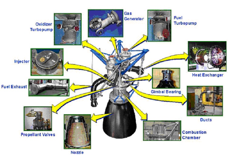
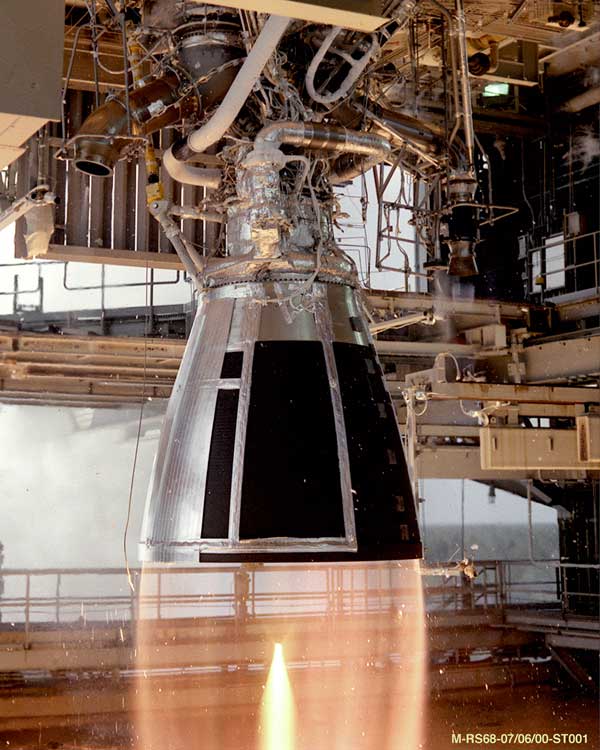
The Common Booster Core is powered by a single RS-68A engine that is the most powerful Hydrogen-fueled engine in the world. The engine was developed by Rocketdyne Propulsion and Power, California and is now marketed by Aerojet Rocketdyne. RS-68A shares commonality with the Space Shuttle’s RS-25 engines, but is overall of a simpler design to reduce manufacturing complexity and cost from $50 million for a single SSME to $14 million for RS-68A. The engine requires about 80% fewer parts than the Shuttle’s engine translating to a cut in labor of 92%.
Differences between RS-68A and RS-25 become evident in their turbopump design. While SSME required 170 individual parts for its LOX pump and 200 components were part of the LH2 pump, RS-68 only needs 40 LH2 pump parts and 25 parts for the LOX pump.
RS-68 provides 2,950 Kilonewtons of thrust at liftoff and has a vacuum thrust of 3,370 Kilonewtons. It has a dry weight of 6,747 Kilograms and provides a specific impulse of 409 seconds. The engine can be throttled between 55% and 100% of rated thrust using a simple single-step throttle profile. It operates at a propellant mixture ratio of 5.97 and has an expansion ratio of 21.5, operating at a chamber pressure of 196 bar.
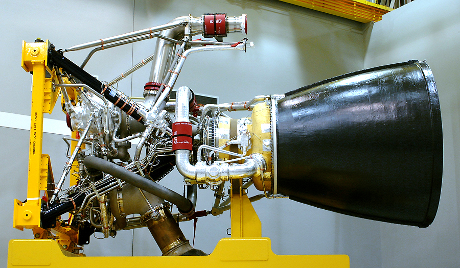
The RS-68A is a cryogenic booster engine using a basic gas generator cycle. The engine consists of a gas generator driving the turbines of two independent turbopumps feeding a combustion chamber that is using a channel-wall design. Inner and outer skins brazed to middle separators form cooling channels as part of a simple engine cooling design using the flow of hydrogen to cool the chamber while the engine nozzle uses ablative cooling through an ablative layer that slowly burns away during operation of the engine.
The RS-68 to RS-68A upgrade included two major design modifications to increase the sea level thrust of the engine by 190 Kilonewtons to 3,137 Kilonewtons, also increasing the vacuum impulse by five seconds to 414 seconds. This was made possible by switching the engine turbine nozzles from an axis-symmetric design to three-dimensional nozzles in order to reduce turbine blade loading and to expand the operational range of the LOX and LH2 turbopumps. The impulse was improved by increasing the number of main injector combustion elements for better mixing and combustion efficiency.
Additional upgrades made to the engine include a new bearing material that is more resistant to stress corrosion cracking, an improved manufacturing technique of the second stage fuel turbopump blisk to reduce risk of cracking, improved LOX pump chill sensors and improved hot gas temperature sensors to accurately maintain engine performance parameters. A new gas generator igniter with less foreign object creation is part of a later upgrade of the RS-68A.
RS-68A made its first test firing in 2008 and completed its certification test in 2010 with full certification of the engine in 2011. Delta IV Heavy made its first launch with the RS-68A in 2012 lofting the classified NROL-15 satellite.
Employing an open-cycle design, the RS-68A consists of a central Gas Generator that uses part of the fuel and oxidizer flow from the two turbopumps of the engine that are spun-up by pressurized helium during engine start. To start up, RS-68A first opens its Gas Generator and Main Fuel Valves and GG LOX valve at T-5.5 seconds, applying helium for turbopump sin-up and actuating engine igniters. This ensures a fuel-rich engine start needed to maintain safe engine temperatures during the ignition sequence which can never be oxidizer-rich. The LOX side opens up its Main Valve at T-2.0 seconds and spins up its turbopump, delivering high-pressure oxidizer to the Gas Generator to sustain the operation of the turbines of the LOX and LH2 turbopumps to deliver propellants to the engine.
The high-pressure gas from the Gas Generator is divided into two outflow paths, one over to the LOX pump’s turbine, the other over to the fuel-turbopump. After driving the turbines, the gas is dumped overboard. On the oxidizer side, the gas generator gas flows through a heat exchanger that uses a portion of the LOX flow through the Main Oxidizer Valve to generate gaseous oxygen that is used for tank pressurization – delivered to the LOX tank through a pressurization line that includes pressure regulators to control the tank pressure.
The turbine gas from the LH2 side is directed through a movable nozzle that is actuated for roll control of the Common Booster Core when flying without its strap-on CBCs later in the mission. After passing through the Main Fuel Valve, the Liquid Hydrogen is run through the regenerative cooling cycle of the combustion chamber. Transitioned to a gaseous state, part of the Hydrogen flow is used to pressurize the LH2 tank during flight. Pre-launch pressurization of the propellant tanks is accomplished using Helium gas.
Launch Vehicle Control during first stage flight is provided by the main engine. Pitch and Yaw are controlled by gimbaling the engine while Roll Control is accomplished by vectoring the RS-68 turbine exhaust gases.
| Type | Common Booster Core |
| Inert Mass | 26,400kg |
| Launch Mass | 228,400kg |
| Diameter | 5.1m |
| Length | 40.8m |
| Propellant | Liquid Hydrogen |
| Oxidizer | Liquid Oxygen |
| Fuel&Oxidizer Mass | 202,000kg |
| Tank Structure | Al-Isogrid, Separate Bulkheads |
| LOX Tank Length | 9.4m |
| LH2 Tank Length | 26.3m |
| LOX Mass / Volume | 172,500kg / 151m³ |
| LH2 Mass / Volume | 29,500kg / 416m³ |
| Tank Pressurization | Gasified Propellants |
| Guidance | From 2nd stage |
| Propulsion | 1 RS-68A |
| Cycle | Open Cycle, Gas Generator |
| Thrust (SL) | 3,137kN |
| Thrust (Vacuum) | 3,560kN |
| Chamber Pressure | >196bar |
| Engine Length | 5.20m |
| Engine Diameter | 2.43m |
| Engine Dry Weight | 6,747kg (RS-68) |
| ISP (Vacuum) | 414s |
| Mixture Ratio | 5.97 |
| Nozzle Ratio | 21.5 |
| Throttle Capability | 57.5%-108% |
| Pitch, Yaw Control | Engine Thrust Vector Control |
| Roll Control | Vectoring of GG Exhaust Nozzle |
| Restart Capability | No |
| Burn Time | 242s |
| Stage Separation | Pyro bolts, Springs |
Strap-On Common Booster Cores
Delta IV Heavy uses two Common Booster Cores that are attached to the CBC in the center in a strap-on fashion to serve as liquid-fueled boosters, delivering additional thrust for the first minutes of flight.
The CBCs functioning as boosters are attached to the central core using thrust struts that interface with the interstage section of the launcher to transfer loads from the boosters to the rest of the vehicle.
Additional attachment points reside in the base of the vehicle right above the engine heat shields. All interface points include pyrotechnic separation devices that are used to jettison the boosters after burnout.
Delta IV Heavy does not have a propellant crossfeed capability. For launch, all three CBCs are fired at full thrust before the RS-68A engine of the central core throttles down to 57.5% of rated performance to save propellants.
Depending on mission requirements, the throttle-down of the core occurs approximately 50 seconds into the flight.
The two Common Booster Cores functioning as boosters continue flight at full thrust, consuming all their propellants in 242 seconds with separation coming two seconds after RS-68A cutoff.
By running on 57.5% for the initial portion of the flight, the Common Booster Core has propellants left to continue to power the vehicle after Booster Jettison.
The RS-68A Engine throttles back up to 108% and burns for 88 seconds following booster separation.
At T+328 Seconds, the Common Booster Core shuts down and separates from the vehicle shortly thereafter using pyrotechnic bolts and springs that push the spent CBC away.
Delta Cryogenic Second Stage
| Type | Delta Cryogenic Upper Stage |
| Diameter | 5m |
| Length | 13.7m |
| Inert Mass | 3,490kg |
| Propellant | Liquid Hydrogen |
| Oxidizer | Liquid Oxygen |
| Fuel&Oxidizer Mass | 27,220kg |
| Tank Structure | Al-Isogrid, Separate Bulkheads |
| LOX Tank Length | 4.0m |
| LH2 Tank Length | 4.8m |
| Tank Pressurization | Gasified Propellants |
| Guidance | Inertial from RIFCA |
| Propulsion | 1 RL-10B-2 |
| Thrust | 110kN |
| Engine Length | 4.14m |
| Engine Diameter | 2.21m |
| Engine Dry Weight | 277kg |
| Specific Impulse | 464sec |
| Nozzle Ratio | 250:1 |
| Nozzle Extension | Yes |
| Ox. To Fuel Ratio | 5.88:1 |
| LOX Flowrate | 20.6kg/sec |
| LH2 Flowrate | 3.5kg/sec |
| Burn Time | Variable (1,125sec) |
| Engine Start | Spark Igniter, Restartable |
| Attitude Control | RL-10 Gimbaling (Pitch, Yaw) |
| ACS | Redundant Attitude Control System |
| ACS Propellant | Hydrazine |
| ACS Thrusters | 12 x MR-106D (4 Pods) |
| MR-106D Thrust | 21 – 41 N |
| Specific Impulse | 227 – 234 s |
| Chamber Pressure | 8.6 – 17.2 bar |
| Propellant Pressure | 13.8 – 21.0 bar |
| Flowrate | 9.5 – 17.7 g/sec |
| Min. Impulse Bit | 0.63Ns |
| Max Burntime | 1,000sec |
| Thruster Mass | 0.6kg |
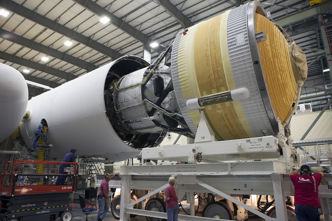
The Delta IV Heavy launch vehicle uses the larger of the Delta upper stages that has an increased diameter of five meters. The Delta Cryogenic Second Stage with a five-meter diameter has a stretched version of the original LOX tank of the four-meter stage, still remaining at the original diameter of 3.2 meters while the LH2 tank has its diameter widened to five meters, allowing the stage to carry a total of 27,220 Kilograms of cryogenic propellants for consumption by the RL-10B engine of the Upper Stage.
The LH2 tank is located above the LOX tank with a truss structure connecting the two tanks that use individual bulkheads. The space in between the two tanks is used to facilitate helium pressurization bottles, attitude control system tanks and the launch vehicle’s avionics known as Redundant Inertial Flight Control Assembly (RIFCA), located on a shelf below the LOX tank.
Overall, the LOX tank of the DCSS measures 4.0 meters in length while the LH2 tank is 4.8 meters long. The entire engine compartment and LOX tank as well as the intertank section and lower segment of the LH2 tank are protected in the interstage section that remains with the Common Booster Core after separation. The upper section of the LH2 tank and the payload adapter are protected by the payload fairing so that only the 5-meter segment of the LH2 tank is actually visible on the exterior of the launcher when in its liftoff configuration.
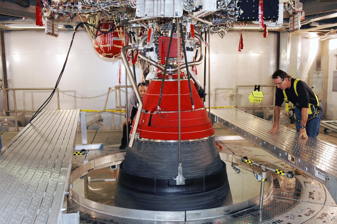
The Delta Cryogenic Second Stage is powered by a single RL-10B-2 engine that is part of the RL-10 family that can look back on a history of several decades having completed its first test in 1959 after being developed by Pratt & Whitney. Over the years, the engine underwent a number of modifications, going through several generations used on different launch vehicles. The RL-10A version of the engine has been powering the trusted Centaur upper stage for decades, currently used in its RL-10A-4-2 evolutionary stage while previous RL-10A version were employed by the Saturn I and DC-X vehicles.
The RL-10B-2 version of the engine with enhanced performance through an extended nozzle is only used by the Delta IV launcher. Another version of the engine, RL-10C is currently being tested for use on Centaur and a derivative of the engine known as Common Extensible Cryogenic Engine (CECE) has completed demonstration tests that included a record-setting deep throttling capability.
The RL-10B engine delivers 110 Kilonewtons of thrust at a specific impulse of 464 seconds employing an expander cycle. The engine features an extendable nozzle that utilizes an electromechanical system that moves the radiatively cooled nozzle extension into position on the regeneratively cooled nozzle segment immediately after stage separation. Overall, the engine is 4.14 meters long with its extension in place, creating a diameter of 2.21 meters and a high expansion ratio of 250, optimized for operation in vacuum conditions. The engine has a dry mass of 277 Kilograms and operates at a mixture ratio of 5.88.
RL-10 is a closed Expander Cycle Engine which does not rely on a gas generator to deliver the hot gas that drives the turbopump turbines of the engine. Instead, the turbines are driven by expanded hydrogen gas that is generated by running the flow of Liquid Hydrogen from the LH2 turbopump through the regenerative cooling system of the upper nozzle segment and the combustion chamber. The gasified Hydrogen then passes to the main turbine of the engine, spinning the LH2 turbopump as well as the LOX turbopump through a gearbox.
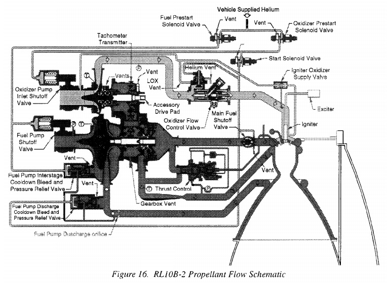
RL-10 includes seven engine valves starting on the fuel side with the Fuel Pump Inlet Shutoff Valve and on the oxidizer side with the Oxidizer Pump Inlet Shutoff Valve. Fuel flow into the combustion chamber can be stopped by the Fuel Shutoff Valve that is located just upstream of the combustion chamber injector.
This valve is used to rapidly cut the fuel feed to the engine for shutdown and its closure also allows the chilldown of the LH2 turbopump through overboard vents without any fuel entering the chamber. Engine LH2 pump chilldown is accomplished by opening Fuel-Cool-Down Valves 1 & 2 that vent coolant overboard during chilldown. These two valves also provide fuel pump bleed during pre-start and pressure relief during shutdown.
Thrust of the engine is controlled by a Thrust Control Valve located in a bridge between the fuel cooling outlet on the engine and the combustion chamber fuel inlet to bypass the turbine and thus regulate turbine power and overall engine thrust. Normally in a closed position, the system is mainly used to control thrust overshoot during engine start and to maintain a constant chamber pressure during steady state operation.
In the oxidizer line downstream of the pump is a Oxidizer Flow Control Valve that is used to regulate the LOX flow to the chamber for the regulation of the mixture ratio that is commanded by the Propellant Utilization Unit of the engine which controls the MR for an optimized propellant consumption. A second OCV is employed to regulate the bleed flow during engine start.
Engine start on the RL-10 is accomplished by using the pressure differential between the fuel feed and the near-vacuum in the chamber that forces fuel through the system after the Fuel Shutoff Valve is opened and FCV-1 is closed. FCV-2 remains in an open position to prevent stalling the LH2 pump of the engine in start-up. In the initial stages of start-up, heat from the ambient metal is sufficient to generate Hydrogen gas to start driving the turbopumps and initiate the combustion process in the chamber, heating up the chamber and nozzle to operational levels. For start, the Oxidizer Control Valve is partially closed to ensure a fuel-rich ignition, limiting chamber pressure in order to maintain a pressure differential in the fuel system until the turbopumps can accelerate.
When the pumps are at flight speed, pneumatic pressure is used to close the Fuel Cooldown Valve and open the Oxidizer Control Valve to achieve the planned LOX pump discharge properties. The opening of the OCV leads to a sharp increase in chamber pressure that can lead to thrust overshoot which is prevented by a temporary opening of the Thrust Control Valve until stable steady-state conditions are reached for engine operation.
In steady state operation, RL-10 consumes 20.6 Kilograms of LOX per second while LH2 flow is approximately 3.5 Kilograms per second.
Engine shutdown is a simple process accomplished by closing the Fuel Shutoff and Fuel Inlet Valve and at the same time opening the Fuel Control Valves to bleed fuel from the system. Oxidizer flow is cut by closing the Oxidizer Control Valve and LOX Inlet Valve. Friction losses lead to the spin-down of the turbines and pumps.
The DCSS uses high-pressure Helium to keep its LOX tank at flight pressure while the LH2 tank uses gaseous hydrogen from the engine bleed that is delivered via regulators that ensure proper tank pressurization.
Propellant management is accomplished by directing hydrogen boil-off from the tank to aft-facing thrusters that deliver sufficient thrust for propellant settling, keeping up a uniform two-phase system between liquids and gases within the propellant tanks. Propellant settling can also be provided by the attitude control system of the second stage.
The attitude control system of the Delta Cryogenic Second Stage consists of 12 hydrazine monopropellant thrusters installed in four modules on the upper stage to deliver control around all three axes as well as additional propellant settling capability. Each module features three thrusters, two lateral and one axial. Fed from several hydrazine bottles, the thrusters use the catalytic decomposition of hydrazine over a metallic catalyst bed.
The MR-106D thrusters are manufactured by Aerojet Rocketdyne with each lateral thruster delivering 21 to 41 Newtons of thrust (smaller 17-27N versions of the MR-106D are not used by DCSS). MR-106D can operate at propellant pressures of 13.8 to 21 bar with chamber pressures varying from 8.6 to 17.2 bar. Flow rate varies between 9.5-17.7g/sec. The thrusters use single seat valves operating at 28 Volts. The engines create a specific impulse of 227 to 234 seconds and are capable of operating in pulse mode with a minimum impulse bit of 0.63Ns while operation in steady state mode up to 1,000 seconds is also possible. Each thruster weighs about 0.6kg with an overall mass per Rocket Engine Module of 2.5 Kilograms.
DCSS control in yaw and pitch is provided by an electromechanical Thrust Vector Control System that gimbals the RL-10 main engine while roll control relies on the attitude control system. The ACS is responsible for three-axis control during coast phases including thermal control maneuvers and re-orientations for spacecraft separation.
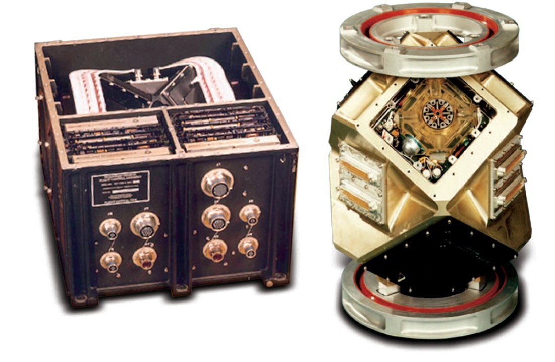
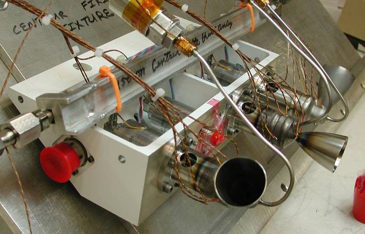
The DCSS also facilitates RIFCA, the Redundant Inertial Flight Control Assembly which provides primary guidance and control of all stages of the Delta IV flight. Manufactured by L-3 Space & Navigation, the RIFCA made its debut in 1994. The unit is triple redundant and measures 43 by 36 by 24 centimeters in size with a mass of 33 Kilograms and a power demand of 75 Watts. The system is connected to all launch vehicle actuators and sensors using a MIL-STD-1553 data bus. RIFCA uses six ring laser gyros and six accelerometers to accurately determine the vehicle’s attitude and body rates operating at rates of up to 30 degrees per second and achieving an accuracy of under 0.08 degrees.
Powered by batteries, the DCSS and operate for 2.3 hours in its standard configuration, although batteries can be added to support missions up to 7 hours that also require additional hydrazine tanks for attitude control system propellant. After payload separation, the second stage can stay active to make a Contamination and Collision Avoidance Maneuver or a Deorbit Burn before passivation.
Payload Fairing
| Type | Long Delta IV Fairing |
| Diameter | 5m |
| Length | 19.1m |
| Separation | Pyrotechnic Activation (Actuators) |
| Construction | Sandwich Construction |
| Graphite-Epoxy/Foam Core | |
| Type | Long Delta IV Fairing |
| Diameter | 5m |
| Length | 19.1m |
| Separation | Pyrotechnic Activation (Actuators) |
The Payload Fairing is positioned on top of the stacked vehicle and its integrated payloads. It protects satellites or other spacecraft against aerodynamic, thermal and acoustic environments that the vehicle experiences during atmospheric flight. When the launcher has left the atmosphere, the fairing is jettisoned by pyrotechnical initiated systems. Separating the fairing as early as possible increases ascent performance. Payload Fairing design limits Payload Volume.
For the Delta IV Heavy Version, only 5-meter diameter fairings can be used, because smaller fairings do not fit on top of the large second stage. Two different versions with lengths of 19.1 and 19.8 meters are available to accommodate different payload dimensions. The smaller version of the DIV heavy Fairing uses the conventional Graphite-Epoxy Sandwich Structure whilst the large 19.8-meter is an Aluminum Isogrid Structure.
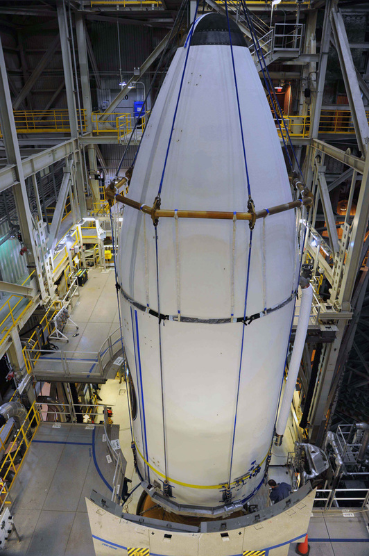
The fairing is separated by pyro bolts and spring jettison actuators that push the two halves away from each other.
Payload Fairings are outfitted with acoustic panels, access doors and RF windows. Also, the Payload Fairing is connected to a purge air system to ensure a controlled environment. Off-pad encapsulation is provided to improve safety standards and limit on-pad time.
Payload Adapters/Fittings
Payload Adapters interface with the vehicle and the payload and are the only attachment point of the payload on the Launcher. They house equipment that is needed for Spacecraft Separation and ensure that the satellite or spacecraft is secured during powered flight.
A variety of payload adapters is available to satellite customers in order to fit a large number of spacecraft dimensions and interfaces. 7 different adapter models are currently available. Most of those have a clamp band payload separation mechanism. It is also possible to design new adapters to accommodate a variety of spacecraft.