
Dawn Spacecraft & Mission Overview
Dawn is a space probe operated by NASA to study two of the three known protoplanets in the asteroid belt to look into the early stages of the solar system of which these asteroids hold a detailed record, having undergone only minor alteration over the course of the evolution of the solar system.
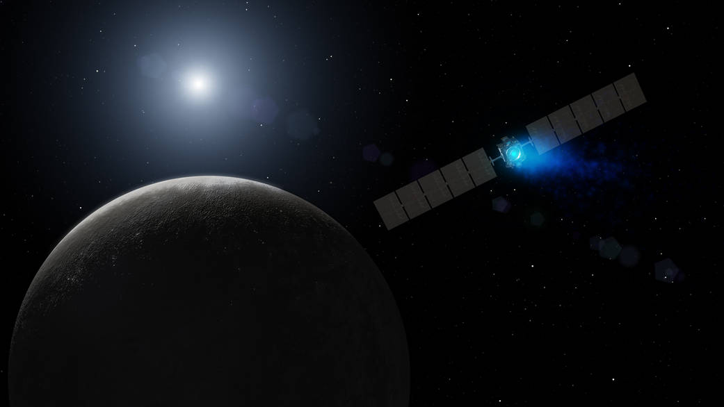
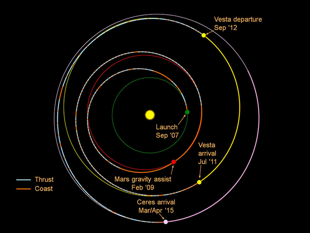
Outfitted with a series of remote sensing instruments, Dawn lifted off in 2007 and arrived at asteroid Vesta in July 2011 for a 14-month survey mission before heading off on a two-and-a-half-year journey to Ceres, the largest object in the asteroid belt. Arriving at Ceres in March 2015, Dawn is set to explore a second world that formed early in the history of the solar system, but shows noticeable differences to Vesta.
Ceres and Vesta were chosen for the Dawn mission as two contrasting protoplanets, one icy and cold while the other was believed to be rocky. Evidence suggests that both objects formed early in the history of the Solar System, however, it is believed that Vesta differentiated rapidly while Ceres may have a differentiated interior and likely formed several million years after the first solar system bodies were formed.
Studying these two objects will fill a gap in the scientific understanding of the solar system as they fit in between the formation of the inner rocky planets and the icy bodies of the outer solar system.
Spacecraft Overview
The Dawn spacecraft platform was manufactured by Orbital Sciences (now Orbital ATK) and its instruments and a range of other components were developed at NASA’s Jet Propulsion Laboratory, the University of California and participating institutions in Germany (Max Planck Institute & German Aerospace Center) and Italy (Italian Space Agency and INAF). Dawn is Orbital’s first purely scientific spacecraft headed beyond Earth orbit and the first purely scientific spacecraft to employ ion propulsion.
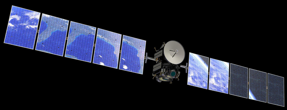
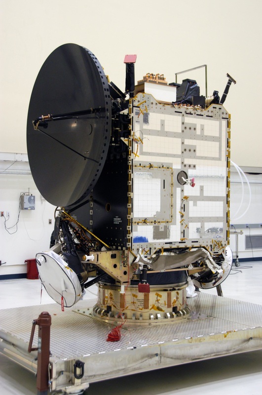
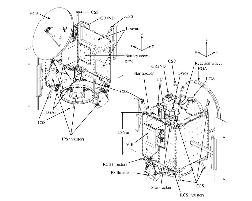
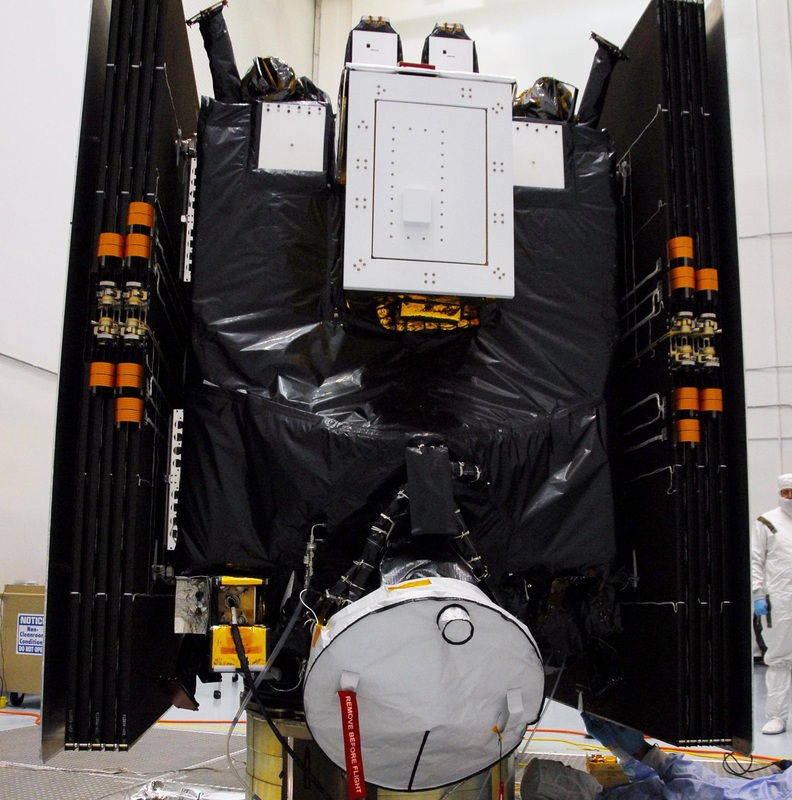
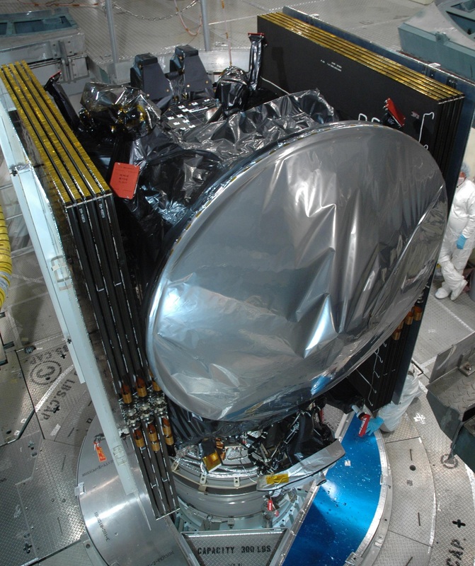
Dawn consists of a central spacecraft body that houses all subsystems and instruments and provides mounting structures for a large parabolic High Gain Antenna and two deployable solar arrays. Overall, the spacecraft platform measures 1.64 by 1.27 by 1.77 meters with a total launch mass of 1,217.7 Kilograms – 747.1kg spacecraft dry mass, 425kg of Xenon propellant for the ion engines, and 45.6kg of Hydrazine propellant for the chemical propulsion system. In its stowed configuration, with the solar arrays locked in the launch position, the spacecraft is 2.36 meters wide. When deployed in space, the spacecraft measures 19.8 meters from tip to tip with both solar arrays fully extended.
The spacecraft was designed for an operational life of ten years with at least one level of redundancy in all critical systems and onboard fault detection and protection to allow the spacecraft to autonomously switch between primary and secondary systems. Dawn uses heritage from previous missions including GALEX, SORCE, and Orbital’s Star Satellite bus as well as the Deep Space 1 mission, the first spacecraft to demonstrate the long-term use of ion thrusters for maneuvering in space.
Mechanical Subsystem
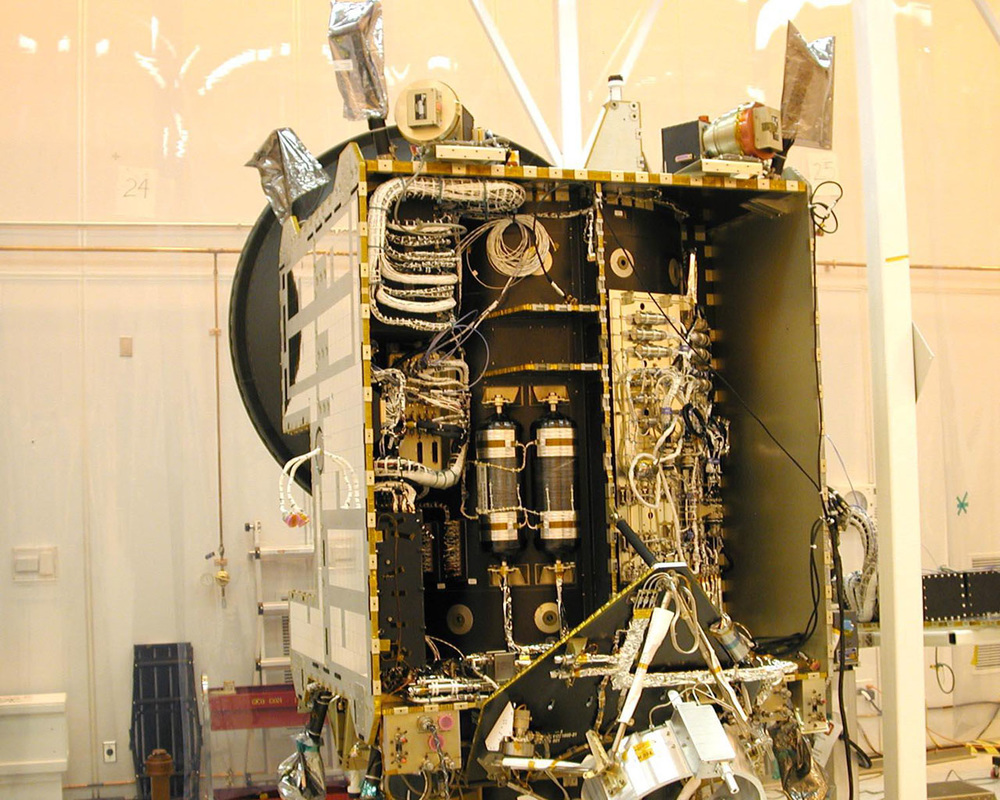
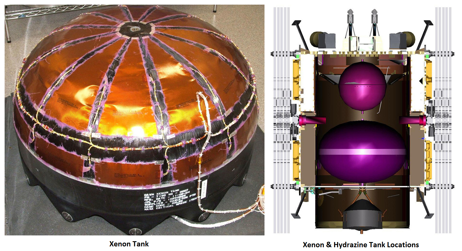
A graphite composite cylinder builds the core of the Dawn spacecraft, running the entire length of the vehicle to provide mounting surfaces for internal and external panels and to transfer forces to the spacecraft, especially during the launch sequence. Inside the cylinder are the propellant tanks for the ion engines holding Xenon propellant and the tank feeding the hydrazine thrusters.
The central cylinder is surrounded by internal panels that consist of aluminum cores and graphite-epoxy face sheets. These panels provide most of the mounting structure for the various satellite subsystems. External panels, also consisting of aluminum cores with facesheets, provide mounting structures for external systems such as thrusters and radiators.
The panels and –Z deck section are joined with composite L-band brackets. The external +/-X and +Z deck panels consist of graphite-epoxy honeycomb structures while the Y panels use aluminum facesheets and aluminum honeycomb cores to facilitate the radiators and heat pipes.
Power System
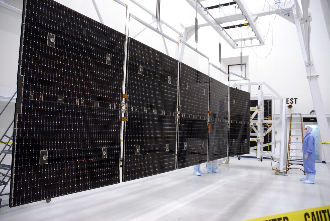
The Dawn spacecraft is equipped with two power-generating solar arrays, each consisting of five rectangular panels for a total area of 38.2 square meters. Each of the arrays is 8.3 by 2.3 meters in size and weighs 63 Kilograms. On the front side, each array is covered with 5,740 InGaP/InGaAs/Ge triple-junction solar cells to deliver a total power of 10.3 Kilowatts at a distance to the sun of 1 Astronomical Unit (Earth’s Orbit) and 1.3kW at 3AU and at the end of the spacecraft’s operational life. The solar arrays are pointed to the sun by two Solar Array Drive Mechanisms controlled by dedicated electronics.
A 80-140-Volt raw power supply from the solar arrays is accepted by the High Voltage Electronics Assembly that delivers the two spacecraft power buses. Dedicated avionics control the state of charge of the single 35 Amp-hour Nickel-Hydrogen battery of the. The spacecraft uses a 28-Volt main bus for all satellite subsystems except the ion engine system, distributed by a Power Distribution System.
The bus operates at an operational range of 22 to 35 Volts that is maintained depending on the state of charge of the battery. Bus protection is provided a Fuse Protect Assembly. A separate Power Conditioning Unit delivers a second power bus at 80 to 140 Volts to run the ion engines of the vehicle.
The cable harness installed on the Dawn spacecraft consists of over 9,000 individual cables with a cumulative length of 25 Kilometers and a mass of 83 Kilograms.
Propulsion System
The Dawn Spacecraft combines the advantages of an electrical propulsion system using the ionization and acceleration of Xenon in an electric field, and a traditional chemical propulsion system consisting of low-thrust engines used for attitude control and delta-v maneuvers. Three different types of propulsion are required for the Dawn mission: 1) large changes of the velocity of the spacecraft to reach its destinations, 2) small changes in delta-v in a short period of time for trajectory corrections and the setup of flybys and orbital insertion, and 3) momentum management on the spacecraft’s reaction wheels.
Dawn’s chemical propulsion system uses Hydrazine monopropellant that is fed to 12 thrusters from two separate tanks that are pressurized before flight using Helium gas.
Six 0.9-Newton thrusters are part of one thruster string, each with redundant Seat Control Valves interfacing with the main propellant line that connects each string with the tank through a latch valve and filter. Each of the tanks is equipped with a redundant pressure transducer.
The thrusters use the catalytic decomposition of Hydrazine over a heated metal catalyst bed to generate combustion gases that are expelled at pressure to generate thrust. Dawn’s chemical propulsion system launches with a total propellant mass of 45.6 Kilograms. Six of the thrusters are needed for three-axis control, the other serve a redundant function. They are used during momentum dumps from the reaction wheels, can assist in spacecraft attitude control and deliver short-duration delta-v changes for the correction of the spacecraft trajectory and the setup of flybys and orbital insertions.
The engines are capable of operating in pulse mode for spacecraft attitude control and in steady-state mode for Cruise Maneuvers and other translational burns. The thrusters also provide de-saturation of the reaction wheels – spinning the wheels down while countering the resulting force with the engines. Thrusters are installed on the +/-X and –Z decks of the spacecraft.
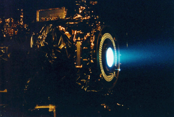

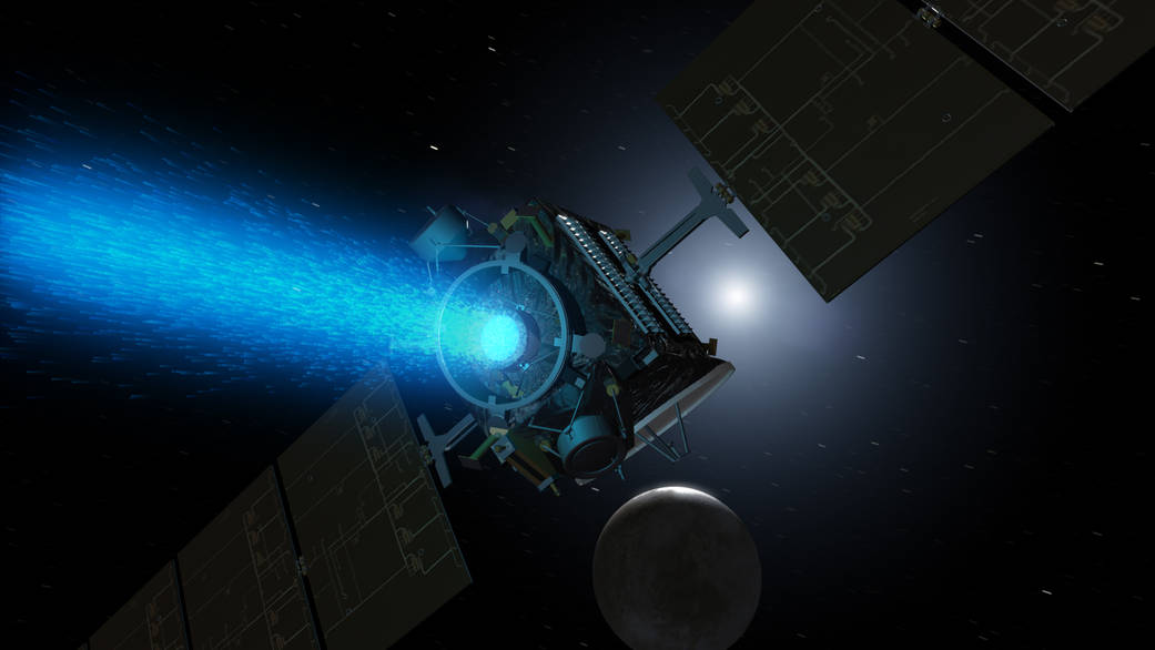
In contrast to the chemical thrusters that deliver a high thrust at low specific impulse, ion thrusters can only deliver a fraction of the thrust at a much greater impulse – requiring them to operate for a long period of weeks at a time to generate the required change in velocity. Ion thrusters use ions to create thrust in accordance with momentum conservation. The method of ion acceleration varies between the use of Coulomb and Lorentz force, but all designs take advantage of the charge/mass ratio of the ions to create very high velocities with very small potential differences which leads to a reduction of reaction mass that is required but also increases the amount of specific power compared to chemical propulsion.
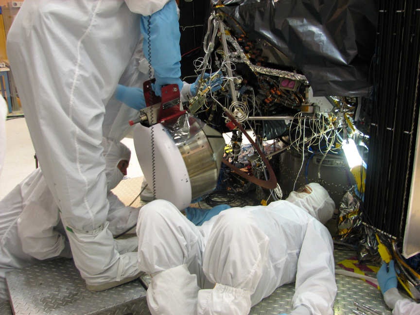
Dawn is equipped with three ion thruster assemblies, one installed on the –X side, one on the +X side and one in the center of the central cylinder. Each Flight Thruster is 33 centimeters in diameter and 41cm in length weighing 8.9 Kilograms. It consists of a series of grids and electrodes, a neutralizer, ion generator, accelerator, gas distributor and control equipment. Two Power Processor Units deliver power to the various components of the thruster, with one in active mode and the other in standby, ready to take over in the event of a problem with the primary unit. Each Flight Thruster is installed on a Thruster Gimbal Assembly that allow each thruster to be gimbaled individually along two axes by +/-8 degrees to provide some control over the thrust vector which is needed to allow the solar arrays to point at the sun for maximum power generation while thrusting in the correct direction.
The thrusters operate by releasing a small amount of Xenon atoms, about 3.25 milligrams per second, into a chamber where they are ionized through collisions with electrons that are released from heated electrodes and accelerated in a magnetic field. The Xenon gas is fed from a 425-Kilogram supply loaded into tanks that are located in the central cylinder of the satellite. The Xenon Feed System consists of the Xenon Tank, the Xenon Control Assembly, two plenum tanks and the High-Pressure Subassembly.
Power from the Solar Arrays is routed to the Power Drive Unit that delivers 28-Volt regulated power to the two Digital Control & Interface Units that control the various components of the Ion Thruster System, also interfacing with the main power bus controller. The Power Processor Units receive regulated 28V power from the Power Drive Unit and 100V raw power that is conditioned in the PPUs to be supplied to the three thrusters. The two PPUs are interconnected by a dual field joint so that either unit can be used to drive either of the three thrusters.
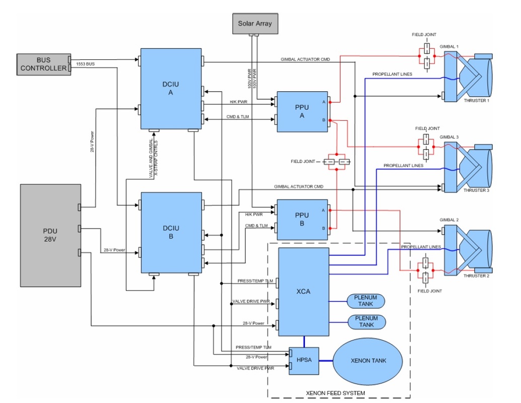
The Xenon Control Assembly is connected to the Xenon Tank via the High-Pressure Subassembly that regulates the pressure down to fill two Plenum Tanks that are connected to the three thrusters. Nine valves are installed in the interconnecting tubing of the Xenon Feed System. Small portions of low-pressure Xenon are delivered to the engines as commanded by the Digital Control and Interface Boards that are also providing the control of the two-axis gimbals.
Xenon atoms that are injected into the Ion Thrusters are ionized through the collision of electrons that provide sufficient energy to the outer electrons of the Xenon atoms for them to be ejected from the atoms to create ions with a positive electrical charge. These ions are then accelerated between two electrode grids that are run at high voltage, quickly accelerating the Xenon ions that are then expelled from the thruster. The negative voltage of one of the accelerator grids prevents ions from the beam plasma outside the thrusters from streaming back which would decrease the generated thrust. The ejected ions push the spacecraft in the opposite direction according to Newton’s third law.
On the exterior of each thruster is a neutralizer that emits electrons near the exiting ion beam to ensure that equal amounts of positive and negative charge are expelled, thus preventing the spacecraft from gaining an excessive electrical charge that could damage components.
Each of Dawn’s ion engines delivers up to 92 Millinewtons of thrust at a high specific impulse of 3,100 seconds. As an additional feature, Dawn’s thrusters can support active throttling to cope with different power budgets that are available at different stages of the mission. Thrust can be throttled from 19 to 92 Newtons over 112 stages that can be commanded by the controller, operating each thruster at a power level between 525 and 2,600 Watts.
Initially, when Dawn is close to the sun and the solar arrays generate 10,000 Watts of power, the spacecraft can run all three thrusters at full throttle. Heading deeper into the solar system towards the Asteroid Belt, Dawn switches off one and then two of its engines and later also starts reducing power levels on the third thruster due to lower light intensity and higher demands from the spacecraft heaters, reducing the overall availability of power for propulsion.
All in all, the ion engines supply a delta-v of 11 Kilometers per second during the Dawn mission, operating for a total of over 2,000 days.
Thermal Control System
Given Dawn’s expected journey from the orbit of Earth up to a distance of 3AU and the different operations of the spacecraft with associated thermal fluctuations, the Thermal Control System was designed to deal with a great variation in the thermal environment experienced by the spacecraft. Dawn uses a combination of passive and active thermal control equipment to transport heat away from electrical components when the spacecraft is going through a hot environment and keep components above their minimal survival temperatures during passive coast phases and asteroid orbits.
The majority of heat-producing electronics are installed on the Y-axis panels of the spacecraft: the electrical power system electronics, communications equipment, High-Voltage components, Power Distribution Unit, Fuse Assembly, Solar Array Drive Electronics, Battery, RF amplifiers and Transponders are located within a cube structure on the +Y panel while the –Y panel facilitates the Command and Data Handling Electronics, the Ion Thruster Electrical Equipment, Central Electronics Units, Attitude Control Electronics and Propulsion Power Units. That is why the Y-panels are constructed of aluminum honeycomb with thermally conductive aluminum face sheets instead of graphite-epoxy materials.
In each Y-panel, there are 14 heat pipes using a combination of L-shaped and straight ones, providing sufficient overlap to deal with heat pipe failures. The external surfaces of the Y panels provide sufficient radiating surface that is controlled by Multi-Layer Insulation coverage. The balance between the high heat loads occurring during ion thruster operation and lower loads during passive phases is maintained through the use of thermal louvers to regulate the Optical Surface Reflectors.
Two large louvers are installed on the –Y panel with a total louvered area of 70% of the radiator area and one large and one small louver on the +Y panel covering up to 80% of the radiator area. The louvers are fully closed at +12°C to prevent excessive cool-off of the spacecraft, they are fully opened at +30°C for full radiation of heat into space. The overall aim of the louvers is to reduce the heater power demand in cold environments.
The components with the tightest thermal requirements is the spacecraft battery which uses conductive and radiative isolation along with heaters that are actuated based on temperature readings. A large number of heaters and temperature sensors are used across the Dawn spacecraft. The tanks and propellant lines are lined with heaters and wrapped in Multilayer Insulation to keep propellants from freezing.
The heater systems use a redundant architecture to maintain minimum temperatures on components. Most heaters are software controlled based on thermostat readings from the associated heater zones.
Thermostatic backup heaters are used to maintain minimum temperatures in the event of a switchover of the Central Electronics Unit as a result of Fault Protection. Zones that do not have thermostatic heaters use a secondary control loop through the Fault Protection System to keep operating even when CEU control is temporarily interrupted.
External non-radiator, non-equipment surfaces are covered in Multilayer Insulation Blankets consisting of 15 layers plus a Beta Cloth that provides the primary protection against micrometeoroids. When at 3AU, the active Thermal Control System demands around 200 Watts of power, about 15% of the spacecraft’s total power supply.
Attitude Determination & Control System
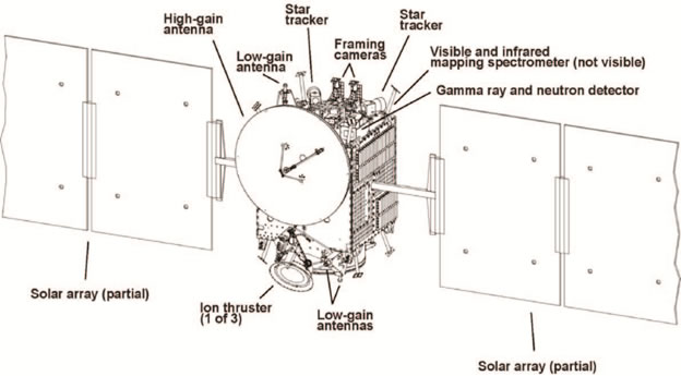
Dawn uses a series of attitude determination sensors including star trackers, inertial measurement units and sun sensors while attitude actuation is provided by four reaction wheels and the chemical thrusters. All functions of the Attitude Control System are controlled by two Attitude Control Electronics that interface with the reaction wheels, the Inertial Reference Units, the sun sensors, the Central Electronics Unit, the Solar Array Drive Electronics and the Reaction Control System Drivers.
Two Star Trackers are installed on the +Z panel of the spacecraft with their boresight pointed to the +Z axis of the spacecraft that nominally points to the -X direction. The two star trackers are each offset by 30° to the spacecraft X axis and +/-90° around the Y axis.
Each Star Tracker acquires optical imagery of the star-filled sky along a 25-degree field of view using a CMOS detector that operates at a frequency of up to 5Hz. Images acquired by the Star Trackers are analyzed by an onboard software algorithm that compares the positions of known bright stars with a catalog of constellations to calculate the precise three-axis orientation of the spacecraft. This calculation is done within the electronics box of the star tracker, not involving the spacecraft computer. Attitude quarternions are delivered directly to the Attitude Control Electronics.
Each of the two optical star tracker heads weighs 1.5 Kilograms while the electronics box has a mass of 4kg. The star trackers can acquire three-axis frames at body rates of up to 8 deg/sec within 2.5 seconds of power-up. Data from the Star Trackers is delivered to the Onboard Computer, the Attitude Control Electronics and Ion Propulsion Gimbal Drives to allow the controllers and actuators to control the attitude of the craft and direct the thrust vector of the ion thrusters.
Dawn is equipped with 16 Coarse Sun Sensors that are installed on all panels of the spacecraft to allow the craft to calculate the position of the solar vector and orient its solar arrays accordingly in the event of a spacecraft safe mode. The sensors are solar cells that allow the onboard computer to determine the solar vector through readings of the power output of the various cells.
Dawn is equipped with three Two-Axis Rate Assemblies (TARAs) provided by Kearfott Corporation which are mechanical, spinning mass gyros. Using three units allows for redundant three-axis attitude determination. Each 2-Kilogram unit includes one gyroscope that can measure body motion up to 20 degrees per second to allow the spacecraft to dampen attitude rates and the star tracker to acquire an attitude frame. The Sun Sensors and TARAs interface with the Attitude Control Electronics via analog RS-422 connections.
Attitude control is primarily provided by a Reaction Wheel Assembly. The RWA consists of four wheels to achieve three-axis control with built-in redundancy and a Wheel Drive Electronics Box that has one dedicated channel for each wheel. The reaction wheel assembly is a rotating inertial mass – when accelerating the wheel, the satellite body to which the wheels are directly attached will rotate to the opposite direction as a result of the introduced counter torque.
The RWA weighs about 20 kilograms and is 40 centimeters in diameter and 18 centimeters high. The wheels can deliver a torque of up to 2Nm and an angular momentum of 16Nms.
The Attitude Control Electronics receive wheel speed telemetry from the Reaction Wheels and command torque settings via an analog line. The thrusters are commanded by discrete on-times from the ACE directly to the seat valves while the Solar Array Drives deliver array position telemetry and receive discrete commands from ACE that is commanding the step-setting based on the current vehicle attitude and solar vector determination.
Command & Data Handling Subsystems
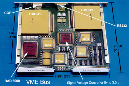
The Dawn spacecraft is controlled from two redundant Central Electronics Units that interface with all spacecraft subsystem controllers and is capable of auto-commanding spacecraft functions, execute commands sent from Earth, handle all payload and systems data, and deliver housekeeping and stored instrument data to the communications system of the spacecraft. The Command and Data Handling Subsystem runs the CDHS flight system and Attitude Control System flight software.
Each of the Central Electronics Units hosts a RAD 6000 processor that runs the flight software for all onboard functions including commanding, fault protection, autonomous operation, mass memory, uplink and downlink, and payload and telemetry data processing. The BAE RAD 6000 is a 32-bit single board computer that offers radiation hardening to operate in the harsh space environment. The computer operates at a maximum clock rate of 33MHz and a processing speed of 35 MIPS (Million Instructions per Second). The CPU consists of 1.1 million transistors. It has an L1 cache memory of 8KB and controls up to 128MB of SRAM memory.
The spacecraft control unit also includes 1GB of Random Access Memory and 3MB of non-volatile memory storing the flight software and command sequences without a loss of data in case of a power outage. Dawn hosts an 8Gbit mass memory used to store instrument data ahead of downlink to the ground.
The two Central Electronics Units, the two Attitude Control Electronics Units and the two sides of the Power Distribution Unit are fully cross strapped to allow them to operate in any combination with the flight computers autonomously commanding switches between systems when triggered. Dawn uses 1553 high speed Data Buses and analog RS-422 interfaces to interconnect all controllers and actuators, the payloads and the various electronics systems as well as the telecommunications system.
The Central Electronics Units and Attitude Control Electronics consist of various electronics cards connected by a backplane including low-voltage power supplies, input/output cards, processor cards, and various control boards hosting the different systems drivers.
Telecommunications System
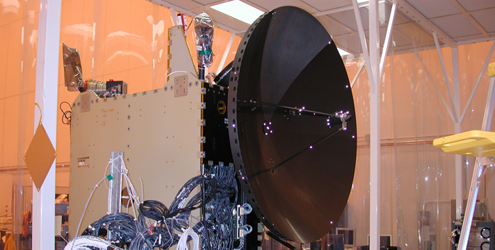
The Dawn Communication System supports X-Band command uplink and downlink of telemetry, ranging, gravity science and instrument data. Dawn uses NASA’s Deep Space Network ground stations for tracking, uplink, downlink and gravity science. Payload data is downlinked at high speed via the single High-Gain Antenna of the spacecraft while command uplink and telemetry downlink is accomplished via Low Gain Antennas.
The heart of the communications system are the Small Deep Space Transponder and the Traveling Wave Tube Amplifier – two of each unit are installed on the +Y panel of the spacecraft with cross strapping possible between all units as part of a redundant architecture. Power from the SDST output is split to both TWTAs and RF switches connect the receive antenna paths to either SDST receive port.
Each of the three Low Gain Antennas receive and transmit with signals being separated by a common diplexer that isolates the receive and transmit paths.
The High-Gain Antenna uses a 1.52-meter diameter parabolic reflector and operates at a carrier frequency of 8,435 MHz achieving data rates up to 128kbit/s using BPSK modulation. The three Low Gain Antennas are installed on the +X, +Z and –Z panel of the spacecraft and operate at a 7,179MHz carrier frequency and reach uplink data rates up to 2,000bps, also using BPSK modulation.
Dawn’s Instruments
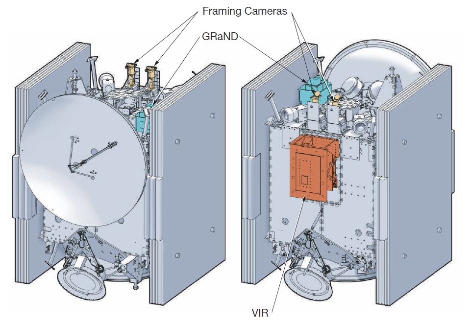
The Dawn Spacecraft is equipped with three scientific instruments plus one passive experiment:
- Two Framing Cameras (FC) developed at the German Aerospace Center and the Max Planck Institute for Solar System Research
- Visible and Infrared Spectrometer (VIR) developed by the Italian Space Agency
- Gamma Ray and Neutron Detector (GRaND) developed by Los Alamos National Laboratory
- Gravity Science, accomplished through the tracking of radio signals from the spacecraft
Initially, Dawn was conceptualized to carry a suite of five instruments – the three instruments listed above and a magnetometer and laser altimeter. Budgetary reasons led to the cut of these two instruments from the mission concept in 2004. Overall, the Dawn payload suite weighs 35.25 Kilograms.
Visible and Infrared Spectrometer (VIR)
Dawn’s VIR instrument is a successor to the VIRTIS – Visible and Infrared Mapping Spectrometer of the Rosetta and Venus Express spacecraft and also includes heritage of the Visible and Infrared Mapping Spectrometer of the Cassini orbiter studying Saturn. The VIR instrument generates spectral frames of 256 (spatial) by 432 (spectral) covering a wavelength range of 250nm to 5μm by using two separate channels and detectors.
VIR is the second German contribution to the Dawn project, dedicated to measuring the thermal radiation from the asteroid, either as emitted or reflected radiation that, when broken down in a high-resolution spectrum, can provide information on the chemical composition of certain areas of the asteroids.
The VIR instrument serves all of Dawn’s scientific objectives, determining the mineral composition of surface materials in their geological context. It is capable of differentiating between surface materials such as ice, dust and rocks and can determine the composition of rocky materials, providing a detailed set of information on the heterogeneity of the asteroid. VIR is designed to identify water-bearing minerals and spot a possible atmosphere of the asteroid and determine its composition, if present.
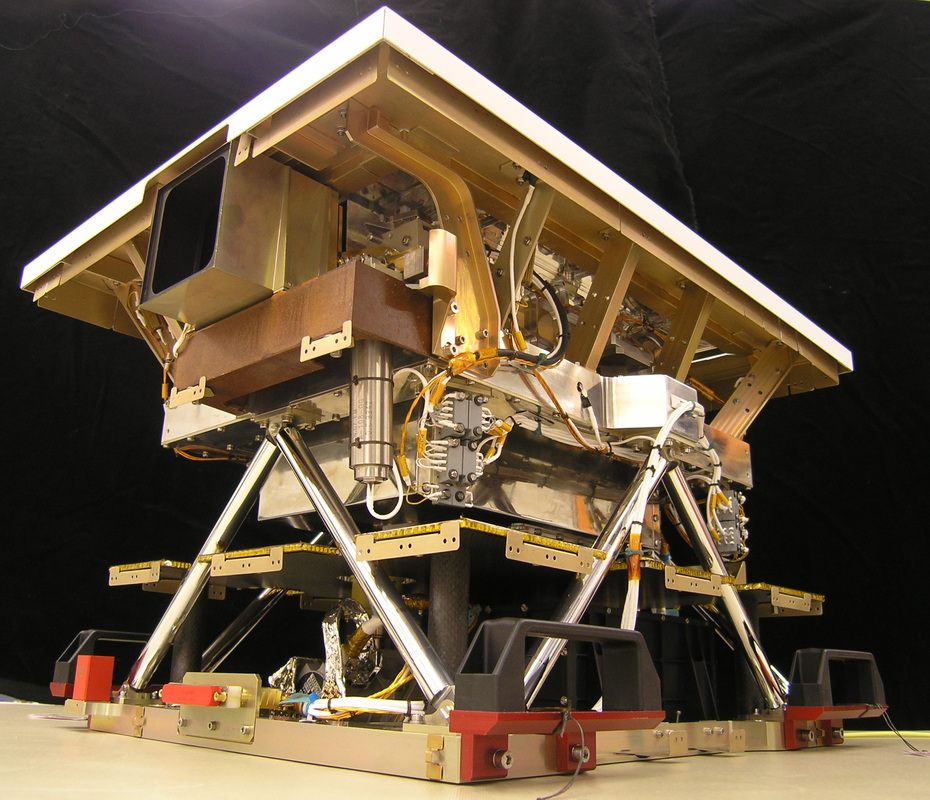
VIR is comprised of a Shafer Telescope (sub-aperture Cassegrain) coupled with an Offner grating spectrometer. A Proximity Electronics Box is located inside the optical head building the interface to the Main Electronics Box of the instrument. Overall, VIR weighs 9.3 Kilograms, without its mechanical spacecraft interface and requires 17.6 Watts of electrical power when operating. The instrument’s optical head weighs 5kg, the electronics assembly 3kg and the cooler and motor assembly around 1.3 Kilograms.
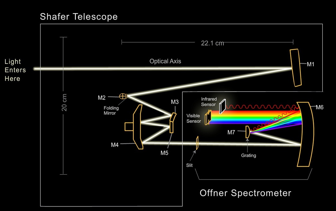
The Shafer Telescope consists of a 47.5-millimeter aperture to allow radiation to enter the optics of the instrument that consist of five mirrors, installed on an optical bench machined from a single aluminum billet to act as a cold plate and provide the necessary stability to maintain the optical components in good alignment. The primary mirror of the instrument is a scanning mirror that is driven by a torque motor to select the area that is to be imaged.
Passing the folding mirror, the radiation is directed through the foreoptics comprised of three mirrors, focusing the light onto the entrance slit of the spectrometer.
The Offner Spectrometer uses a slit that is 9.53 millimeters in length and 0.038mm wide. After passing through the entrance slit, the light is dispersed by a spherical convex diffraction grating. VIR uses a single grating for both, the visible and infrared channels, featuring two different groove densities ruled in the different areas of the grating.
The inner 30% of the grating are ruled with a higher groove density to achieve the required spectral resolution for the visible light channel while the outer 70% use a lower groove density to generate the appropriate resolution across the broad infrared spectral range – corresponding to 70% of light intensity entering the instrument that is directed into the infrared channel. The larger collecting area in the infrared channel compensates for the lower solar irradiance in that spectral band. After being dispersed, the radiation is refocused by a convex mirror that directs the visible and infrared portions of the spectrum to their dedicated detectors.
The VIR instrument can be operated in two different modes, either acquiring high-resolution images in the 0.25 to 5 μm wavelength range with moderate spectral resolution, or operating in a high-resolution mode for the infrared channel from 1 to 5 μm and only acquiring moderate-resolution images. When using the high-resolution imaging mode, VIR reaches a spatial resolution of 0.25mard whereas the spatial resolution in the nominal mode is 1mrad. Operated in pushbroom mode, the instrument has a field of view of 64 by 0.25mrad. Using its scanning mirror, VIR achieves a 64 by 64 mrad field of view – corresponding to a 6.4 by 6.4-Kilometer ground area when at a distance of 100km to the surface.
The Visible Channel of the VIR instrument employs a Thompson TH 7896 Charge Coupled Device as detector measuring 508 by 1024 pixels in size using standard 19µm pixels. This detector covers a spectral range of 0.25 to 1,000 nanometers at a spectral resolution of 1.89 nanometers. The CCD detector is operated at a temperature of 150 to 190K to reduce dark currents and yield a higher sensitivity in the near-infrared wavelengths.
The infrared channel facilitates a Mercury-Cadmium-Telluride (HgCdTe) array detector comprised of 38µm pixels. The detector hosts 270 by 438 pixels and is sensitive in a spectral range from 0.95 to 5μm reaching a spectral resolution of 9.44nm (average). A cryocooler is employed to keep the infrared detector at an operational temperature of 65 to 90K by radiating excess heat into space through a dedicated radiator panel.
The VIR instrument features a Proximity Electronics Box that is installed inside the Optical Head, interfacing with all electronic components of the instrument. It hosts a mother board and interface backplane hosting a CCD board interfacing with the visible detector system for image read-out and commanding, an IR board to operate the infrared detector and a scan mirror and cover board that are in charge of actuating the movable aperture cover and the scan mirror based on commands from the Main Electronics Box that is physically separated from the Optical System to avoid a violation of thermal limits given the presence of dissipative electronics.
The Main Electronics Box includes the Digital Processing Units, the Spacecraft Interface for power and data, the motor power supply and the instrument power supply. The power supply delivers electrical power to all instrument subsystems, excluding the cryocooler that interfaces directly with the S/C power supply. Proximity Electronics, cooler, cover and scan mirror actuation is completed by the Power Distribution Unit controlled by the Data Handling and Support Unit.

The Digital Processing Unit of the VIR instrument is shared with the Framing Camera to reduce weight and overall systems complexity. For VIR, the unit is in charge of receiving, pre-processing, compressing and formatting the science and calibration data from the two focal plane assemblies. DPU also controls the power supply to the subsystems, completes health checks of the instrument and conditions status telemetry for both optical systems.
Uplink and downlink data as well as the data interface to the spacecraft are managed by the system and all telecommands intended for VIR are executed by the DPU that also provides timing synchronization between the instrument and the spacecraft and hosts mass memory for the payload data.
The DPU is based on a TCS 21020 32-bit processing unit with 20 MIPS (Million Instructions per Second). The processor has 1Mbyte of EEPROM memory containing the boot code and 4Mbyte of RAM for buffering of spectral data from the instrument. Two 3Gbit mass memory units are used to store instrument data for later transmission to the spacecraft and downlink to the ground.
The VIR instrument can complete inflight calibration by closing the aperture door and using two light sources with known spectra to check for any changes in the optical setup and the sensitivity of the detectors over the course of the long mission duration of the Dawn spacecraft.
Framing Cameras
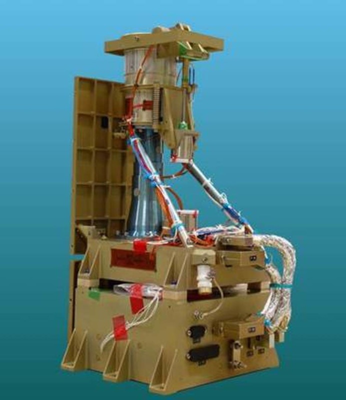
The Dawn spacecraft is equipped with two identical Framing Cameras that are capable of acquiring imagery at different visible wavelengths for a variety of applications. Two cameras are used to create a redundant system given the importance of the cameras for the mission, not only acting as a scientific instrument but also being used for navigation to guide Dawn to its distant targets in the asteroid belt. The cameras were provided by the Max Planck Institute for Solar System Research, Germany.
The scientific objectives of the Framing Cameras include the complete topographical characterization of the two target asteroids, specifically the determination of their volume, spin state, shape, interior structure, physical surface properties, color variation & mineralogy, origin, evolution, age & volcanism, the dust environment and the presence of satellites. Non-scientific applications of the cameras include optical navigation, orbit determination and mission safety.
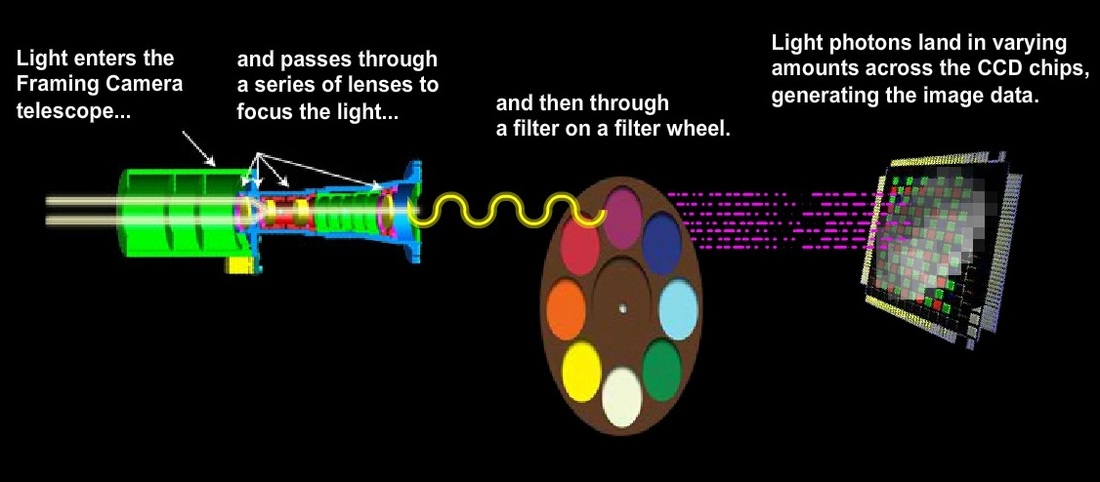
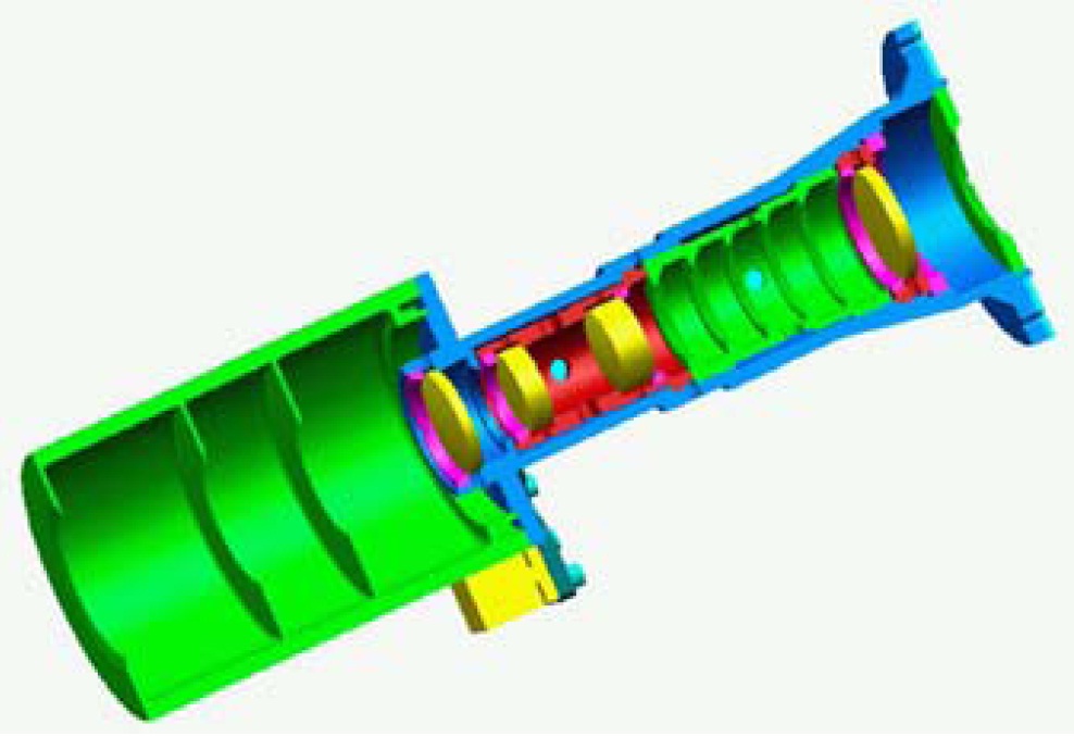
The Framing Camera is a refractive telescope with a frame transfer CCD sensor. Both cameras are installed side by side on the +Z panel of the spacecraft and can be used simultaneously for stereo imaging. Each camera assembly consists of a camera head and an electronics unit housed in a common electronics box. The camera head contains the optical system, the focal plane assembly, read-out electronics, interference filters, and the radiators. Thermal control of the optical heads is accomplished with heater mats that are actuated based on temperature sensor readings. Inside the electronics box reside the Data Processing Unit, the power converter unit and the mechanism controller.
The Framing Camera telescopes have a focal length of 150 millimeters and use a four-lens telecentric anastigmatic design providing an aperture of 19.9 millimeters and creating a field of view of 5.46 by 5.46 degrees. For thermal considerations, the materials chosen for the structural assembly of the Framing Cameras were selected such as to compensate for thermal expansion and contraction in order to keep the optical components aligned for a wide range of temperatures. Stray light minimization is accomplished through the use of a large external baffle and internal shades. A front door that can be opened and closed by a motor is used to keep the interior of the cameras protected from any contamination and direct exposure to sunlight.
The door is kept close whenever the cameras are not in use and flight rules dictate the door to remain closed whenever the ion thrusters or chemical propulsion system is to be used.
Between the optics and the Focal Plane Assembly is a filter wheel with eight slots, outfitted with seven narrowband filters and one open slot, controlled by a Geneva drive that can provide the step-wise movement with only two moving parts and locks as part of a robust system that ensures the wheel reaches the commanded position for imaging. When a filter change in between imaging operations is needed, at least three seconds of delay have to be implemented to facilitate a safe and complete motion of the wheel.
The selection of the detectors for the Framing Cameras was made after considering a number of mission unique factors such as the great contrast that was to be expected between the well lit areas of the asteroids and the dark areas in shadow – requiring a broad dynamic range, the need to observe the bright asteroids and dim starts for navigation – requiring a wide range of exposure times, the minimization of mechanical complexity – requiring the system to rely on an electronic instead of a mechanical shutter, and the cost-factor – preferring the use of a commercial sensor rather than a custom made unit.
The Framing Cameras use Thomas TH 7888A front-side illuminated CCD sensors with an active area of 1024 by 1024 pixels using frame-transfer technology that supports an electronic shutter and reaches a 1.3-millisecond frame transfer, thus limiting frame transfer smear. The 14-micrometer pixels enable the instrument to achieve an angular resolution of 66 μrad corresponding to a resolution of 17 meters per pixel at Vesta and 66 meters per pixel at Ceres.
The actual size of the detector is 1056 by 1092 pixels. The outer pixels are optically masked and not exposed and can therefore be used to quantify instrument noise and dark currents that can be subtracted from the exposed images as part of data processing. A lateral anti-blooming gate is employed to prevent photo-generated charge from being transferred from overexposed regions across the columns which is a known problem in space-imaging systems.
The Framing Camera detector can support exposure times from 1 millisecond to 3.5 hours.
After exposure, the accumulated charge is rapidly shifted from the storage area with a shift time of 1.32 milliseconds. The charge is clocked-out in a row-by-row fashion to the horizontal register and then shifted to the output amplifier. The total readout time is about 1.2 seconds. The pixel-charge is digitized using a 14-bit depth. When in non-read-out mode, the CCD is operated in an idle mode constantly being erased by simultaneous shifting the parallel and serial registers.
The CCD sensor is sensitive for wavelengths between 400 and 950 nanometers. The narrow-band color filters consist of silica substrates with thin-film coatings deposited on their front and backsides. Each filter is 20 by 20 millimeters in size and they are of different thickness depending on their transmission wavelength.

The seven filters have passband widths between 36 and 85 nanometers with central wavelengths of 438 (blue), 555 (green), 653nm (red) for full-color RGB imaging and 749, 829, 917 and 965nm for near-infrared spectroscopic imaging. The filters allow spectral imaging to support the examination of the asteroid’s composition and surface properties.
The focal plane is cooled to –60°C to optimize image sensitivity by reducing dark currents, especially for optimization of imaging in the near infrared wavelengths. Excess heat is radiated to space using dedicated radiator units, one for each Framing Camera optical head.
The Framing Camera system is capable of in-flight calibration by using a calibration lamp to track camera performance over the course of the flight. The lamp is a set of six AlGaInP LEDs that are installed in the uppermost flanges of the objective barrel. When active, the LEDs illuminate the front door of the instrument through a series of pulses with known maxima and half maxima when operated in certain duty cycles and pulse frequency.
The Electronics Box of the Framing Camera contains a fully redundant set of electronics for the two camera heads to allow a fully autonomous operation of each unit in case of a failure within the second string of systems. FC uses a CCD controller based on a Field Programmable Gate Array provided by Actel that is in charge of generating the waveforms for the charge shift and read-out and it produces the timing signals for the exposure setting.
It also supervises the data transfer from the focal plane assembly to the Data Processing Unit using a high-speed serial protocol.
The CCD controller can be operated in diagnostic mode to deliver a synthetic test pattern, a serial read out without line shift, a storage readout without frame transfer and a crop mode only reading the active pixels.
The Data Processing Unit is in charge of processing of the raw image data, storage of payload data, execution of spacecraft commands, transmission of payload data for downlink, and the generation of status telemetry to allow insight into the health of the instrument. The DPU includes a redundant 8Gbit mass memory that can hold over 1,000 raw uncompressed images, but given downlink data limitations, most of the images sent back to Earth will be put through onboard compression. The DPU can support a lossless compression by a factor of two up to a lossy DCT compression by a factor of 10.
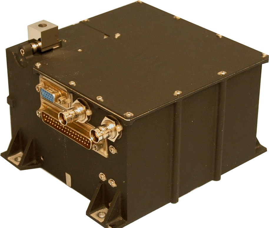
Gamma Ray and Neutron Detector (GRaND)
Dawn’s Gamma Ray and Neutron Detector (GRaND) was developed by the Los Alamos National Laboratory and is designed to detect, identify and quantify strong neutron and gamma-ray signals that can be emitted by radioactive materials which could be present on the surface of asteroids as well as non-radioactive isotopes as a result of bombardment by cosmic rays, thus allowing insight into the elemental composition of the asteroid. The instrument can provide a detailed picture of the composition of the asteroids with special focus on their water content that is of great interest to scientists.
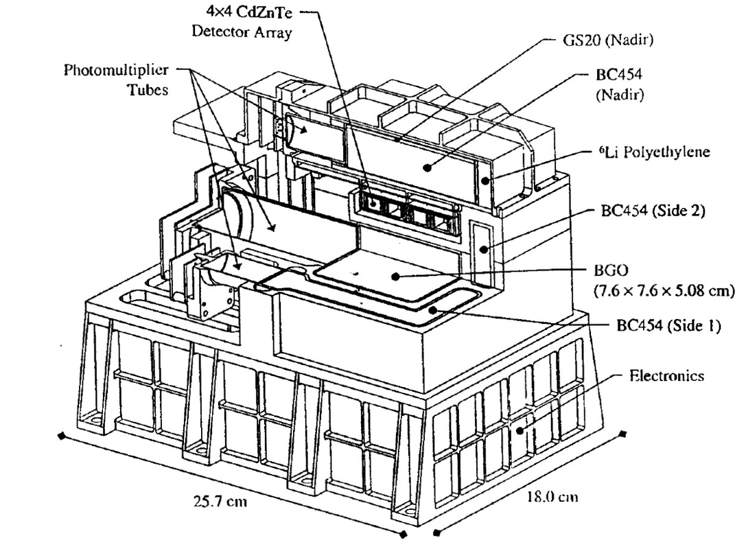
GRaND can provide measurements of a number of elements such as O, Si, Fe, Mg, Ti, Al, and Ca as well as the trace elements H, Gd, U, Th, K and Sm as well as C, N and Cl that build the constituents of ices and and are products of aqueous alteration. The instrument uses a combination of a semiconducting cadmium zinc tellurium crystal detector and a bismuth germanate detector for the measurement of gamma rays. For the measurement of neutrons, the instrument uses scintillators that generate gamma radiation that can be detected by the sensors mentioned before. Water (Hydrogen) can be detected with an accuracy of 3% through gamma rays and 0.02% by measuring neutrons.
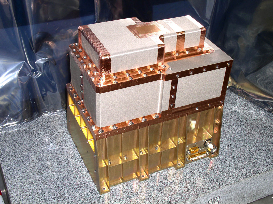
The instrument is 25.7 by 18.0 by 20.3 centimeters in size and has a mass of 10.5 Kilograms with a peak power demand of 9 Watts. GRaND hosts a total of 21 detector elements. It can begin measurements of the asteroids once Dawn reaches a distance of 130 Kilometers.
Data from the instrument will be used to constrain the thermal evolution of Ceres and Vesta, also determining the role water played in the process, determine the contribution of radioisotopes to the global heat balance, study the composition of the primordial solar nebula as a function of heliocentric distance, examine the interior composition of Vesta and Ceres, determine hydrogen sources and answer a number of other scientific questions.
Two different types of sensors are used by the GRaND instrument, scintillator- and semiconductor-based radiation sensors to detect neutrons and gamma rays as well as energetic particles from the space environment that have to be factored into data processing.
A scintillator consists of a volume of transparent material that can interact with energetic particles (electrons produced by gamma particle interactions, and alphas and recoil protons produced by neutron interactions) to convert their kinetic energy into flashes of light (photons) that can be detected by a photomultiplier tube and photodiode detector.
Semiconductors can be used to measure gamma rays since electrons generated by Compton and photoelectric interactions are capable of ionizing the semiconductor – generating electron-hole pairs which can be detected by charge-sensitive amplifiers that measures the amplitude of the charge pulse which is known to be proportional to the energy deposited by a specific gamma ray – allowing a spectrum of incident gamma rays to be created, helping in the identification of the elements that generated the energetic rays.
The GRaND sensors have been arranged in order to pick up gamma rays and neutrons from the target body and differentiate them and cosmic ray backgrounds, also detecting cosmic ray hits on the spacecraft and associated secondary particles. All sensors were selected to be able to operate in the ambient spacecraft thermal environment, not requiring any active cooling systems.
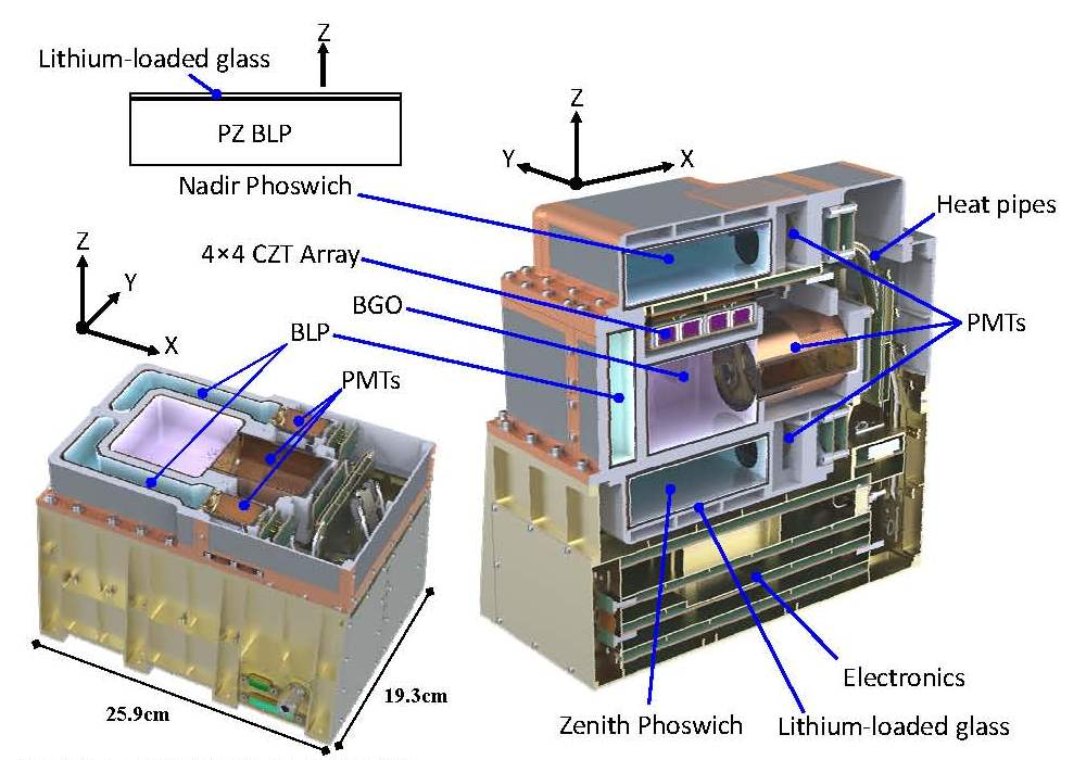
A Bismuth Germanate (BGO) scintillator measuring 7.6 by 7.6 by 5.08 centimeters in size is part of the instrument, located in the center of the scintillator subassembly. The large BGO crystal is coupled with a 5.08cm diameter photomultiplier tube for detection of gamma ray hits. Given the high density and high atomic number of the BGO, the scintillator can detect gamma rays up to an energy of 10MeV.
Two L-shaped Boron-Loaded Plastic Scintillators (BLP) are positioned on the – and +Y side of the BGO and CZT array, surrounding the two detectors.
The 193cm³ BLP crystals act as an anticoincidence shield by rejecting cosmic ray interactions. Additionally, the BLP are sensitive to fast neutrons at energies over 700keV when incident neutrons can participate in elastic scattering with H-atoms of the plastic to generate knock-on protons that produce detectable light by ionizing the scintillator. Light output can also be produced by thermal and epithermal neutrons that can be differentiated by the different light signatures.
A planar array of 4 by 4 Cadmium-Zinc-Telluride (CZT) semiconductor crystals is positioned on the +Z side of the BGO crystal, facing the target asteroid during science mapping. The crystals are 10 by 10 by 7 millimeters in size and feature coplanar grids to mitigate effects such as hole trapping to ensure an acceptable peak shape and pulse height resolution over a wide energy range. The system can measure gamma rays with energies up to 3MeV, covering the densely populated low-energy region of the spectrum which includes gamma rays originating in radioactive decay as well as gamma rays produced by cosmic ray interactions. Therefore, a high resolution on the lower end of the spectrum is highly desirable.
Finally, GRaND hosts a Lithium glass Boron-loaded Plastic Phosphor Sandwich consisting of two BLP scintillators – one on the nadir (-Z) side of the GRaND instrument and one on top (+Z), centered on the CZT array and BGO crystal. Each scintillator is 10.2 by 10.2 by 2.54 centimeters in size and is read-out by a 2.54cm phototube. Thermal neutrons from all sides except the outward facing panels are absorbed by a Gd foil. The outward facing sides are covered by lithiated glass of 0.2cm thickness to absorb thermal neutrons. Because the glass converts all thermal neutrons that are detected by the phototube, the signatures from the BLP can all be attributed to epithermal neutrons, allowing to differentiate between the two types of energetic neutrons.
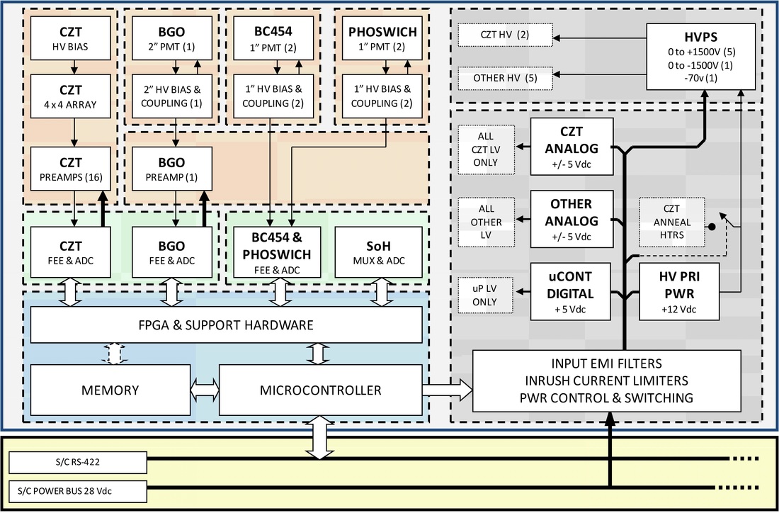
The electronics of the GRaND instrument are comprised of a number of components located directly below the sensors. The Power Supply receives 28V power from the spacecraft and delivers the 5V low-voltage power bus to the instrument electronics and +12V to the High-Voltage power supply that conditions 0 to +1500V for the photomultiplier tubes, and –1500/+70V delivered to the CZT sensors. Data transmission to and from the instrument is accomplished by an RS-422 connection.
A UTMC microcontroller is in charge of instrument monitoring and and commanding. Each of the individual sensors interfaces with its own analog front-end for read-out followed by digitization of shaped analog pulses by dedicated analog-to-digital converters that determine pulse amplitude and timing signals that allow the analysis of coincident events. Engineering telemetry includes the high-voltage values and instrument temperatures. In the normal mode of operation, signals are averaged over one-minute intervals.
Dawn’s Journey
A Long Road to Launch
The Dawn project was initiated in the early 2000s to become a record-setting mission – the first to enter orbit around two planetary bodies during a single mission, and the first scientific mission powered by ion propulsion. NASA appointed Orbital Sciences (now Orbital ATK) with the development and integration of the satellite platform while NASA and participating institutions were tasked with the development of the craft’s three (originally five) instruments.
In 2003, the project was canceled by NASA before being reinstated just three months later to proceed until October 2005 when the project was instructed to stand down. In January 2006, Dawn’s status was updated to ‘indefinitely postponed’ before the official cancelation came from NASA in March 2006.
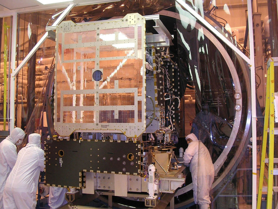
However, Orbital appealed NASA’s decision and offered to finish the construction of the spacecraft at cost in order to build the company’s experience in the manufacturing of deep-space science spacecraft. By late March of 2006, NASA announced that Dawn would not be canceled after all and teams proceeded with the integration of the spacecraft that was completed by September 2006, allowing Dawn to enter final testing on its path to a 2007 liftoff. Despite a relatively significant cost overrun, Dawn finally made it to the launch site in April 2007 with a launch date in June.
Although Dawn made it to the launch site, its troubles were not over yet as liftoff got pushed from the initial June 20 target to the 30th due to delays associated with part deliveries, then to July 7 because of a broken crane at the launch pad that was needed to hoist the Solid Rocket Boosters of the Delta II rocket into position.
During processing at the launch site, Dawn sustained some damage to one of its solar arrays when a wrench slipped off a clamp-band bolt, but assessments showed that the damage was mostly cosmetic and would not cause a launch delay. The weather gods were not in favor of Dawn and its Delta II, pushing the launch from July 8. Range Problems pushed the launch to the 9th and then the 15th.
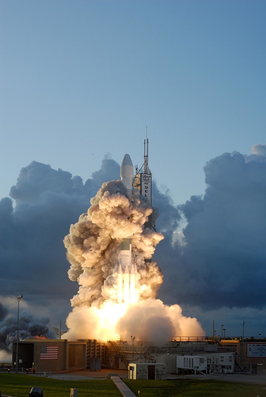
With Dawn slipping well past expectations, teams were instructed to stand down and give priority to the Mars Phoenix Mission that had a much shorter launch window and was therefore put first in the firing line. Phoenix launched on August 4 and cleared the way for the launch of Dawn on September 26 which became the 27th due to bad weather. On launch day, the countdown went down all the way to T-4 minutes when an extended hold had to be called due to a ship entering the hazard area where the Solid Rocket Boosters were forecast to impact. The ship departed the danger zone and Delta II waited out a collision cut-out before finally lifting off at 11:34 UTC on September 27, 2007.
Under the loud thunder of the RS-27A engine and six ground-lit GEM-46 Solid Rocket Boosters, Delta II lifted off with a total thrust of 458.5 metric-tone force, sufficient to quickly loft the 231,900-Kilogram Delta II rocket clear of its tower. The rocket broke the sound barrier just 30 seconds into the flight followed ten seconds later by Maximum Dynamic Pressure. 77 seconds into the mission, the six ground-lit boosters burned out with three air-lit boosters igniting just two seconds later and the six spent motors separating 80 seconds after launch. The three air-lit boosters parted ways with the Delta II two minutes and 40 seconds into the flight. Delta II continued powered flight on its RS-27A engine and dual sustainer engines until Main Engine Cutoff at T+4 minutes and 22 seconds. Stage separation at T+4:31 was followed by the ignition of the second stage’s hypergolic AJ-10-118K engine five seconds later on a burn of four minutes and 22 seconds during which Dawn was exposed by separating the payload fairing once crossing 115 Kilometers in altitude.
The second stage re-started 51 minutes and 35 seconds into the mission to begin pushing Dawn out of Earth orbit, making a burn of two minutes and 40 seconds before handing over to the Star 48 solid-fueled third stage that ignited at T+58 minutes and 44 seconds for a burn of 85 seconds that put Dawn on an escape trajectory. The spacecraft was sent on its way one hour and two minutes after liftoff, deploying its solar arrays and checking in with tracking stations on Earth for the start of an extremely long journey through the solar system.
Journey to Vesta & Operations in Orbit
In order to get to Vesta, Dawn was set for a long period of trajectory adjustments. Dawn is powered by three ion thrusters that are provided with power by two massive solar arrays that span 19.7 meters from tip to tip. The engines deliver a thrust of 90 millinewtons at a specific impulse of 3,100 seconds; they are fed from tanks that initially held 425 Kilograms of xenon propellant that gave Dawn a delta-v budget of over 10km/s. Also, twelve 0.9-Newton Hydrazine thrusters are used for attitude control and assist in orbital insertion.
The first long-term cruise propulsion phase lasted nearly 11 months and ended in October 2008 with a trajectory correction maneuver using the Hydrazine thrusters taking place the next months to set the spacecraft up for a gravity assist of Mars that occurred in February 2009 when the spacecraft came as close as 549 Kilometers to the planet which was used as a welcome opportunity to exercise the craft’s instrument package.
Having passed Mars, Dawn spent over two years in cruise mode, making propulsive maneuvers to set up its date with Vesta.
Arriving on July 16, 2011, Dawn was successfully captured in an orbit around Vesta that is about 525 Kilometers in diameter. Since Dawn was arriving at a largely unknown world, the timing of its orbital insertion could not be calculated precisely because Vesta’s mass properties had not been known yet. It took more than one day to confirm whether Dawn had entered orbit as the spacecraft was not pointing its antenna toward Earth during the operation of its ion engines and had to re-orient once the maneuver was complete to check in with Earth.


Through a series of propulsive maneuvers, Dawn entered its Vesta survey orbit for three weeks in August 2011 before placing itself in a high altitude orbit from late September to early November ahead of a transition into a 210-Kilometer low-altitude orbit where the spacecraft spent half a year until May 2012. To set up for its departure, Dawn boosted itself into another high-altitude orbit in which it flew from June 15 to July 25, 2012.
Originally planned to depart Vesta on August 26, Dawn had to remain in orbit for a little longer to allow teams on Earth additional time to diagnose a reaction wheel problem leading to a departure on September 5 as Dawn set sail on a 2.5-year trek toward Ceres.
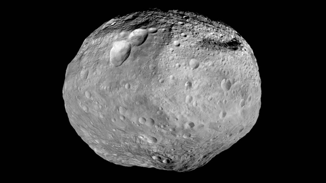
Dawn’s study of Vesta revealed its surface composition, geologic features, internal structure and a number of other properties that were of great interest to scientists. One item of particular interest was an abundance of crevasses on the surface of Vesta that scientists believe originated as the result of flowing water on the surface of Vesta that was present in at least one stage of Vesta’s evolution. Scientists also hypothesize that Vesta is likely one of the last remaining examples of the large planetoids that formed the rocky planets of the inner solar system through collisions of multiple planetoid bodies. Dawn also provided insight into the origin of dark streaks and spots on the surface of Vesta that were caused by ancient asteroid impacts.
Data from Dawn allowed scientists to construct the first-ever geologic map of an asteroid body to help gain an understanding in the different geologic formations on Vesta that could shed light on long-standing questions regarding the formation and evolution of the Solar System in its initial stages.
Final Leg to Ceres
Departing Vesta, Dawn again started a long-term propulsion phase to transition from Vesta’s 2.15 by 2.57-AU orbit to the orbit of Ceres at 2.56 by 2.97 Astronomical Units. With Dawn on the move, teams on Earth worked out how to best deal with the spacecraft’s partially failed reaction wheel system, developing a hybrid attitude mode in which the remaining wheels will be used in combination with the liquid-fueled thrusters when arriving in the mapping orbit at Ceres. Teams also had to deal with a computer re-start to rectify an issue with the main antenna of the spacecraft and in September 2014, one of the ion engines stopped working and Dawn headed into safe mode, requiring teams on Earth to make quick work transitioning to a different engine to keep the gap in propulsion as short as possible.
Beginning on December 1, Dawn snapped its first images of the extended disk of Ceres, however, it took until January 29 for the spacecraft to get close enough to acquire images surpassing Hubble Space Telescope Imagery in resolution. To save propellants, the amount of imaging operations during approach was reduced to nine.
Early in the approach, images from Dawn showed the bright spot already seen by Hubble, but Dawn’s photos showed that there was a companion to the bright spot, residing in the same crater.
Other brighter areas are also shown in other craters, but the pair of prominent features has been the focus of the discussion with guesses on their origin ranging from volcanoes to being bright sub-surface material exposed by impacts. Generally, Ceres has a dark tone and features abundant craters of different geologic ages. Grooves resembling those found on icy moons throughout the solar system can also be seen in the images.
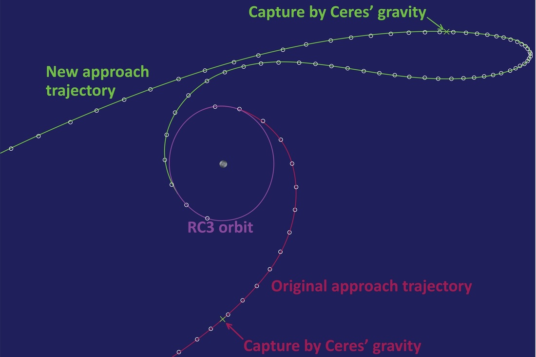
Dawn was captured by the dwarf planet’s gravity at 12:39 UTC on Friday when it was at a distance of 61,000 Kilometers, marking the craft’s arrival after a journey of 4.9 billion Kilometers. It is now the first spacecraft ever to visit a dwarf planet and enter orbit around two different celestial bodies.
Continuing to use its ion thrusters, Dawn will spiral down from a maximum apoapsis down into an orbit around 4,600 by 85,000 Kilometers in late March.
Dawn is aiming for an polar orbit at an initial altitude of 13,500 Kilometers for a first full characterization of Ceres before going down to a survey orbit at 4,400 Kilometers for a three-week surveying operation followed by two months in a 1,500-Kilometer orbit. In this high-altitude mapping orbit, Dawn will acquire near-global maps with VIR and its camera, including stereo imaging. By November, the spacecraft will be in an orbit of 375 Kilometers for three months of gravity investigations and Gamma-Ray and Neutron Detector observations.
Dawn will operate until late 2016, ultimately exhausting its supply of hydrazine fuel and ending up as a satellite of Ceres.
Given the current trajectory taking Dawn past the night side of Ceres, no new images will be available until mid-April reaching a 2.1km/pixel resolution by April 15 when the craft will be at 22,000 Kilometers to Ceres.
