
Chang’e 3 – Mission Overview
Chang’e 3 is China’s first lunar surface exploration mission using a lander and rover. Launching in December 2013, the mission is part of the second phase of China’s Lunar Exploration Program that has the ultimate goal of manned flights to the Moon. The mission is a follow-on to the Chang’e 1 and Chang’e 2 missions and will lay the foundations for future sample return flights that could begin as early as 2017.
Chang’e 1 was launched in 2007 and operated in lunar orbit for one year and four months, performing remote sensing operations using an instrument payload consisting of a high-resolution stereo camera, an imaging spectrometer, a laser altimeter, Gamma and X-Ray spectrometers, a microwave radiometer and a particle detector.
The spacecraft provided a high resolution map of the Moon and a wealth of scientific data including data on the chemical composition of the lunar surface and the particle environment of Earth and Moon.
Chang’e 2 launched in 2010 and had a similar mission using improved instruments. The spacecraft conducted science operations in lunar orbit before starting an extended mission, performing a transfer to the Earth-Sun L2 Lagrangian Point for testing of the Chinese tracking equipment and to demonstrate the operation of deep space missions.
In April 2012, Chang’e 2 departed L2 and headed for a close flyby of asteroid Toutatis that was completed on December 13, 2012 with Chang’e coming as close as 3.2 Kilometers. As of late 2013, the spacecraft was still operational, continuing to cruise through deep space to further demonstrate deep-space operations for future missions.
Data from Chang’e 1 and Chang’e 2 was used to pick a landing spot for Chang’e 3 which is the first Chinese mission to the lunar surface.
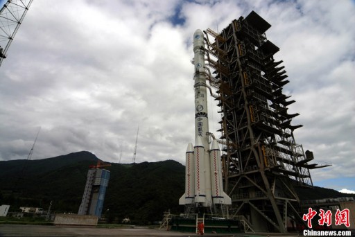
Named for the goddess of the Moon in Chinese mythology, Chang’e 3 launches atop a Long March 3B rocket on December 1, 2013 headed for insertion into Lunar Orbit on December 6. Landing on the surface of the Moon on December 14, Chang’e 3 becomes the first craft to make a soft landing on the Moon in 37 years.
The Chang’e 3 lander as well as the rover carry scientific payloads that are going to be used to study the Moon, other galaxies and stars as well as the near-Earth space environment. The lander is expected to perform a science mission of at least one year while the rover is hoped to be operational for three months or longer to explore the lunar surface.
Lander & Rover Design
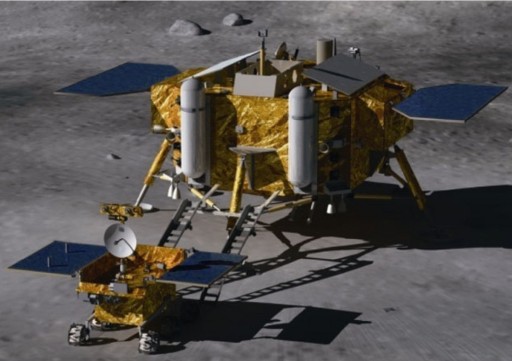
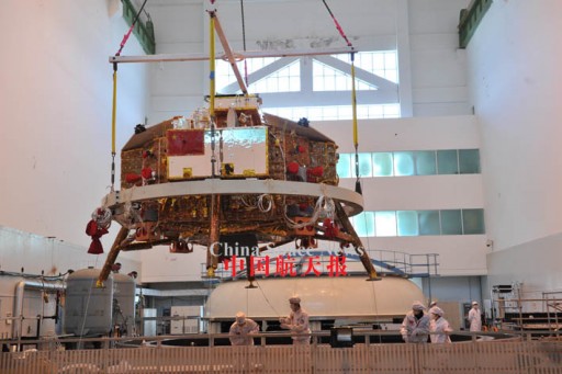
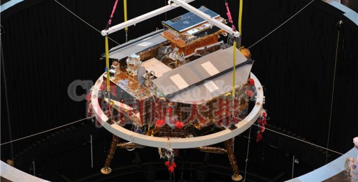
The Chang’e 3 mission incorporates two major components – a Lunar Soft-Landing Vehicle (Lander) and a Lunar Surface Exploration Vehicle (Rover). Overall the lander has a dry mass of 1,200 Kilograms and its landing legs create a vehicle span of 4.76 meters. When standing on the surface, the lander body rests 0.83 meters above the ground. The lander includes all necessary equipment to fly from the Earth to the Moon and perform a soft landing on its surface. Riding to the Moon as a passenger is the small rover weighing about 120 Kilograms. Both, the lander and rover, are equipped with a scientific payload.
https://www.youtube.com/watch?v=IPqh5TxIteM
Lander Design
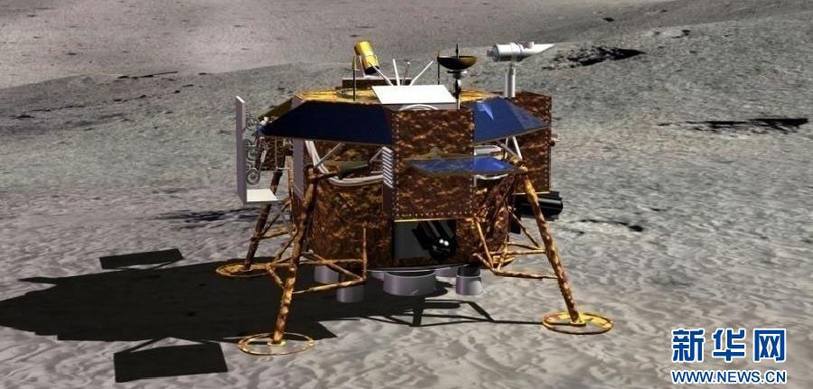
The Chang’e 3 Lunar Lander includes all systems needed for a Trans-Lunar Flight, a soft landing on the Moon and a scientific mission on the surface. Overall, the lander is octagonal in shape with four landing legs that include secondary struts, bumpers and landing pads. The lander has a dry mass of about 1,200 Kilograms. Fully loaded with propellants & carrying the rover, the Chang’e 3 probe weighs approximately 3,700 to 3,780 Kilograms, limited by the capabilities of the Long March 3B launch vehicle.
Power System
The Chang’e 3 lander uses a combination of solar panels and a Radioisotope Thermoelectric Generator (RTG) to meet its power requirements. Two solar panels are installed on the vehicle to deploy in flight & after landing.
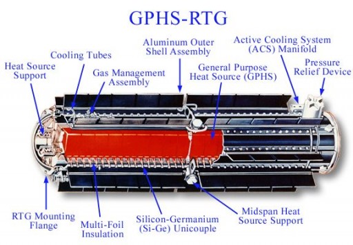
An RTG is of simple design using the thermal energy released by a radioactive material and converting it into electrical energy. Chang’e 3 uses 238-Plutonium Dioxide as RTG fuel. The radioactive Pu-238 decays by emitting alpha-particles which generate heat.
Thermocouples are installed in the walls of the containers with the fuel with the other and of the thermocouples connected to a heat sink so that heat flows through the thermocouples to the heat sink, generating electricity in the process. Thermocouples make use of the Seebeck Effect, converting thermal to electric energy.
The Chang’e 3 RTG was designed with high safety standards, ensuring that the device would remain intact in the event of the launch failure and subsequent impact to prevent the release of radiation.
Using a combination of solar power generation and RTG power allows Chang’e 3 to conduct science operations during lunar day when sufficient power for instrument operation is available, and survive in lunar night using the RTG to power vehicle heaters and core systems in Lunar-Night Sleep Mode.
(There have been contradicting reports on whether Chang’e 3 is carrying an RTG or simpler Radioisotope Heater Units that only provide thermal energy and no electrical power. A number of Chinese papers and other sources explicitly mention an RTG.)
Thermal Control System
The lunar surface environment is relatively harsh – days and nights are 14 Earth days in duration and surface temperatures vary from –175 degrees Celsius during night to more than 100°C in the sun.
Chang’e 3 uses a combination of active and passive thermal control systems. Blankets of multi-layer insulation cover large portions of the vehicle to protect if from excessive solar heating and from cooling when exposed to the vacuum of space during night-time.
The active thermal control system consists of resistive electric heaters that are actuated using thermostat data. Heater power is supplied by the solar arrays and batteries during day. Because Chang’e 3’s batteries would not last over the 14-day lunar night, the heaters also use power provided by the RTG. The majority of power provided by the RTG is used for the heaters and a small fraction is used to sustain the lander’s Lunar Night Sleep Mode in which all systems expect for crucial control and housekeeping systems are shut down.
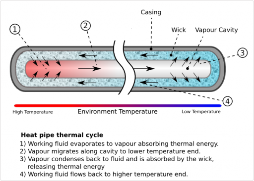
A number of Chinese reports and papers claim that Chang’e 3 is also equipped with a system of gravity-assisted two-phase fluid loops to transport RTG heat to vehicle equipment for survival during lunar night. A two-phase loop design uses heat pipes that feature thermally conductive interfaces with a hot surface (the RTG) and cold equipment that needs to be warmed up. The fluid inside the pipe turns into vapor by absorbing heat from the RTG.
When reaching the cold interface, the fluid condenses into a liquid and releases latent heat to the system. The system uses gravity to return the liquid back to the hot interface to repeat the cycle and constantly transport heat to the internal lander systems.
Propulsion System
A number of requirements have been identified for the propulsion system of the Chang’e 3 lander. The system has to be operated multiple times in the mission in different environments including lunar orbit and the major landing burn. To perform a soft landing, the vehicle’s main propulsion system needs to have throttle capability. In addition, Chang’e 3 needs a secondary propulsion system coupled with an attitude control system for minor trajectory corrections and vehicle attitude control. For the dynamic landing maneuver, the attitude control system has to be of a design that allows quick response to attitude actuation commands.
China has not officially identified the propulsion technology used on Chang’e 3, but based on previous Chinese missions and usual propulsion applications in other space missions, it is more than certain that Chang’e 3 uses a bipropellant system with Unsymmetrical Dimethylhydrazine fuel and Nitrogen Tetroxide Oxidizer.
Chang’e 3 is equipped with a single main engine that was developed for the mission as China’s first throttlable engine for space applications. The high-specific-impulse engine uses a pintle-type flowrate regulating device to adjust its thrust output. Using a ~60-centimeter nozzle with high area ratio, the engine is optimized for operation in vacuum conditions. The engine was baselined to provide 1,500 to 7,500 Newtons of thrust (153 to 765 Kilogram-force) – which is sufficient to lift/land the vehicle in the 1/6G environment of the Moon. The engine can be throttled with a very high accuracy of 7.5 Newtons and features and active cooling system. Propellant tank pressurization is accomplished by using high-pressure gas.
In addition to its main propulsion system, the Chang’e 3 lander also features a propulsive attitude control system that consists of 28 thrusters that are installed on the smaller side panels of the vehicle being canted to allow three-axis control. The system uses a combination of 150-Newton and 10-Newton thrusters.
The lander features eight thruster modules – each consisting of two 150N and one 10N thruster. The remaining four 10N thrusters are installed separately, one on each of the smaller side panels.
Eight of the 150N thrusters are oriented in an identical orientation for dV burns using all or a a number of those engines. These eight 150N thrusters are likely used for smaller Trajectory Correction Maneuvers during the Earth-Moon transfer and small orbital adjustments (& possibly during LOI and landing).
The 10N thrusters are used for attitude control and re-orientation maneuvers. A combination of all ACS thrusters is used for attitude control during main engine burns. Using the relatively high-thrust 150N engines for attitude control provides quick response capability which is required for fast attitude adjustments during the landing phase.
Landing System
In its ambitious landing sequence, the Chang’e 3 lander is dropped from an altitude of 4 meters which required a cushioning landing system on the lander to create a fairly soft landing. The system also has to support the Rover release that is performed after landing. A “cantilever-type” design has been selected for Chang’e 3.
The landing system utilizes four primary landing legs that are equipped with footpads to avoid sinking into the surface. The Chinese used previous lander designs and knowledge on the properties of the lunar dust to develop a landing system that minimizes mass while maximizing stability.
The primary landing struts facilitate bumpers with interior buffer elements to provide shock-absorbing capabilities. The legs are installed at a 30° angle to the lander structure. Multi-functional and single-functional secondary struts are attached to the landing legs to provide additional attach points to the lander body.
Two secondary struts are attached to each of the landing legs. Those also provide flexibility and shock-absorbing capabilities. Chang’e 3’s landing cushion technology employs superplastic materials.
Navigation System
Chang’e 3 makes a fully autonomous landing on the lunar surface without receiving any navigation data from Earth. To accurately find its landing site and perform a soft landing on the surface, the lander is equipped with a number of navigation systems.
The vehicle uses multiple sources of navigation information provided to its main computer to deduce accurate altitude and velocity data. The primary navigation system for the early phase of the descent from orbit is the lander’s inertial navigation platform with built-in redundancy. It is used to measure the change in velocity imparted by the engine burn to determine when the required delta-V target is reached.
Range and velocity measurements are also provided by a large-dynamic-range laser ranging system and a microwave range sensor that become active once the vehicle has reached a certain altitude and orientation above the lunar surface. (Initially, the vehicle flies horizontally, making a retrograde braking burn before changing its attitude for a vertical descent.)
Once in its hovering segment, about 100 meters above the surface, the lander will start acquiring images using its descent camera. The computer will be using a newly developed obstacle-recognition algorithm using optical images and 3D elevation data. Flying horizontally, the lander autonomously finds a flat spot for landing, avoiding any obstacles that can be detected using its systems.
For the final descent, the lander uses a Gamma-Ray Altimeter that provides precise altitude data to the vehicle. This sensor is used to detect the 4-meter engine cutoff point.
Rover Accommodation
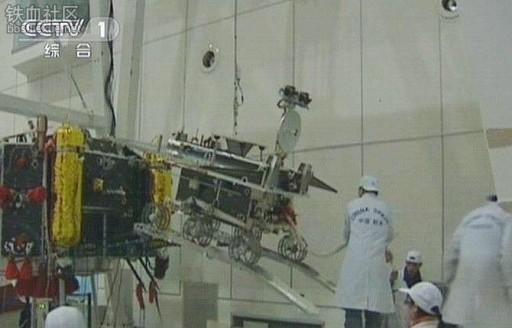
The 120-Kilogram Chang’e 3 rover is firmly attached to the top deck of the lander. One of the challenges of the lander design was to find a way to get the rover down to the surface from the top deck of the lander while minimizing overall spacecraft mass.
Following landing on the Moon, the connection between the lander and the rover is severed using unspecified methods. Two ramps, stowed in the vertical position on the side panel of the lander, are deployed to a horizontal position so that the rover can roll onto them from the top deck.
Then, the ramp is carefully lowered using an electromechanical system to touch the surface and maintain an angle the is within the rover’s mobility system specifications so that the vehicle can safely roll off the ramp and begin its own surface exploration mission.
Lander Instruments
Lunar-Based Ultraviolet Telescope
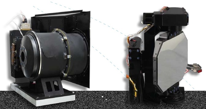
One of the primary instruments of the lander is the Lunar-based Ultraviolet Telescope (LUT) that is used to observe galaxies, binary stars, active galactic nuclei and bright stars. A lunar-based observatory has a number of advantages over Earth-based and space-based observatories.
On Earth, observatories battle the effects of the atmosphere that are often the limiting factors for scientific observations. The Moon’s thin exosphere provides excellent opacity with no atmospheric turbulence and virtually no scattered light emissions.
Space-based observatories require an excellent pointing system for long-term observations of targets. The Moon on the other hand provides a stable platform. Also, the sky’s motion as seen from the Moon is 27 times slower than on Earth, allowing extremely long, uninterrupted imaging campaigns of a target.
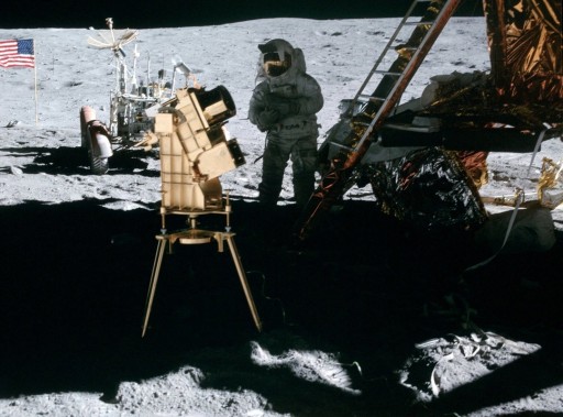
The LUT instrument is the first long-term observatory to be deployed on the Moon. The Apollo 16 mission brought a far-UV telescope to the Moon for short-term observations, collecting nearly 200 images of quality that is considered very poor by today’s standards.
The LUT instrument sets out to perform multiple-day observation campaigns, looking at variable stars and active galaxies in the near-UV band. Objects that are bright in the NUV band include variable stars, binaries, novae, quasars and blazars. LUT will attempt to study the variability of these objects to examine the temperature and accretion rate in order to better understand stellar atmospheres and improve current models.
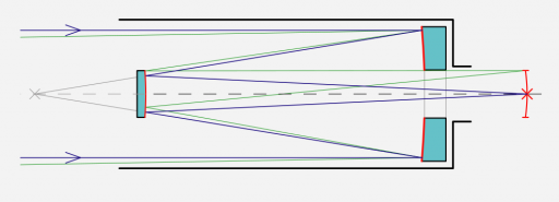
The LUT instrument consists of a Ritchey-Chretien telescope that is a specialized Cassegrain Telescope using a hyperbolic primary mirror and a hyperbolic secondary mirror to eliminate third-order coma and spherical aberration. RCT designs are well-suited for wide-field and photographic observations with good off-axis performance at a large field of view free of optical errors.
LUT has an aperture of 150mm and uses a pointing mirror that features a two-dimensional gimbal to track objects. A Charge-Coupled Device enhanced for observations in the ultraviolet band is used as detector. The CCD uses pixels 13 micrometers in size. LUT covers a wavelength range of 245 to 340 nanometers and is capable to detect objects at a brightness down to 13 mag.
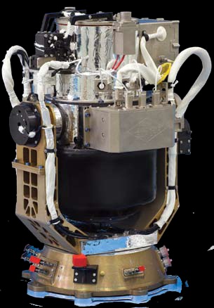
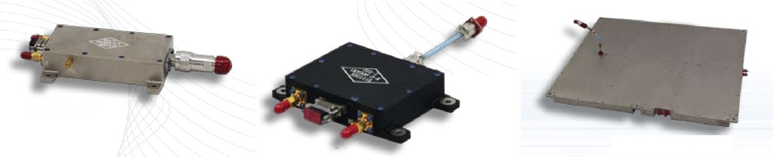
Moon-Based EUV Camera
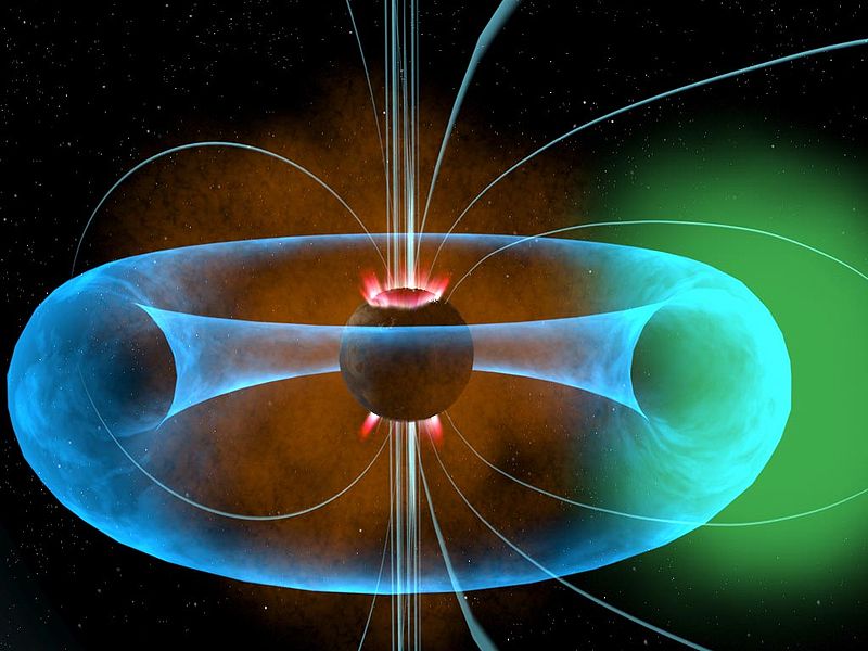
The Chang’e 3 lander also carries a camera that makes observations in the Extreme Ultraviolet band to observe the Earth’s plasmasphere. The plasmasphere is located within Earth’s magnetosphere and consists of low-energy (low-temperature) plasma located above the ionosphere.
The outer boundary of the plasmasphere, the plasmapause, is characterized by a sudden drop in plasma density by the order of one magnitude.
The plasmasphere has been known for relatively well organized particle motion due to the geomagnetic field causing the plasmasphere to corotate with Earth. Recent observations of the plasmasphere, however, are pointing to density irregularities caused by a number of processes. Also, recent observations have shown that the plasmasphere does not always corotate.
Observations of the plasmasphere are possible by detecting resonantly scattered solar radiation at 30.4nm caused by plasmaspheric He+-Ions. He+ is the second most abundant ion in the plasmasphere making up 15% of total plasma density so that measurements of He+ can be used to measure overall plasmaspheric properties such as density and temperature.
The Moon-based EUV Camera of Chang’e 3 has a field of view of 15 degrees and a high angular resolution of 0.1 degrees and a temporal resolution of 10 minutes. The camera head is installed on the top deck of Chang’e 3 using a Pan and Tilt Targeting Mechanism. The instrument uses a multi-membrane optical system and a EUV photon counter sensor as detector. Studying the 30.4nm radiation from the Moon allows Chang’e 3 to observe the entire plasmasphere including plasmapause and plumes on a global scale to examine its structure and dynamics.
Images provided by Chang’e 3 are put through an algorithm to create three-dimensional models of Earth’s plasmasphere.
Lander Cameras
In addition to the primary instruments, the Chang’e 3 lander also includes a series of cameras. Three panoramic cameras are installed on the lander, facing different directions to allow the lander to acquire images of the lunar terrain surrounding the landing site and take photos of the rover as it departs the landing site. The cameras can take still images as well as video. Exact technical details for the cameras were not released.
Camera technology tested on previous missions that is employed on Chang’e 3 include auto-exposure, focus adjustments, high-speed compression of color imagery and static gray image, and sub-sampling methods.
The MastCam instrument was developed by the Institute of Optics and Electronics (IOE) and the Chinese Academy of Sciences (CAS).
In addition to its three Pancams, the lander is equipped with a single Descent Camera that was tested on the Chang’e 2 spacecraft. The Micro-CMOS camera provides images of 1,280 by 1,024 pixels during the descent to the lunar surface. According to reports, the camera acquires imagery at frame rate of more than 10 fps. Details such as exposure times have not been given.
The nadir-facing camera is expected to be active when the lander is hovering 100 meters above the surface of the Moon, taking images of the landing site to help rover mission planners to select drive routes later in the mission. The camera is likely taking images all the way down to the surface as the lander makes its constant low velocity descent to an altitude of 4 meters for engine shutdown.
Previous Chang’e missions also included a range of engineering cameras to obtain images and video of important activities of the spacecraft such as solar array deployment and main engine burns. Whether Chang’e 3 also includes such cameras is unknown.
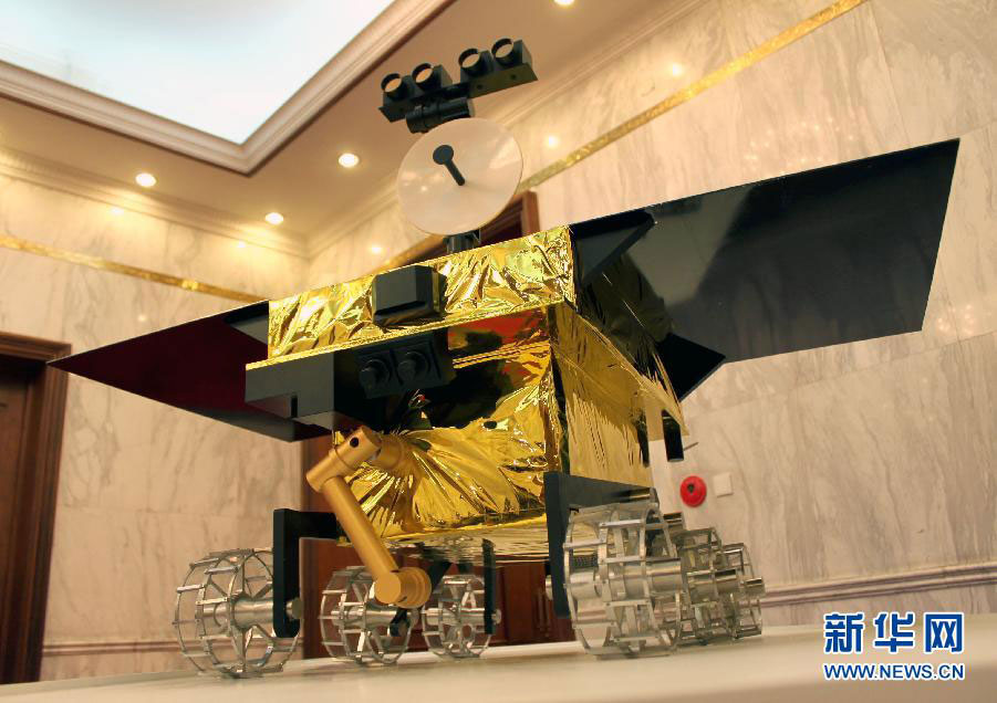
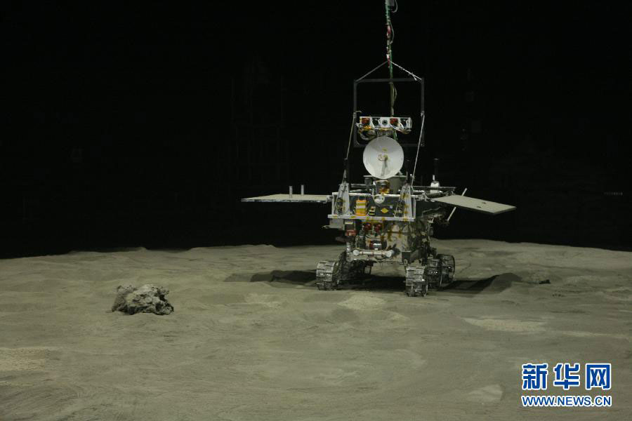
Rover Design
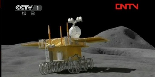
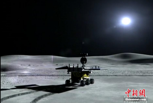
The Chang’e 3 rover has been named Yutu – Jade Rabbit. In the popular Chinese myth, the goddess Chang’e is accompanied by a white pet rabbit named Yutu.
The rover weighs approximately 120 Kilograms including a payload mass of 20 Kilograms. It features a mast that facilitates the vehicle’s stereo and navigation cameras and communication antenna, standing about 1.50 meters tall.
The rover body is a rectangular cuboid that features solar panels and a robotic arm that holds part of the instrument payload. The rover is expected to survive three months in the harsh environment on the lunar surface – three lunar days & nights.
Power & Thermal Control System
Unlike the lander, the Chang’e 3 rover does not use an RTG power source. The rover uses two rectangular solar panels that are locked on the top deck of the rover for launch and descent and deploy shortly after landing. Using the panels to generate electrical power, the rover operates throughout the two weeks of lunar day and charges its battery to survive the long lunar night.
In its Lunar-Night-Sleep Mode, the rover is powered down to a large extent, only running core functions such as health monitoring and powering survival heaters.
Several Chinese sources have reported that the Rover carries Radioisotope Heater Units distributed throughout the vehicle to keep critical components at acceptable temperatures. RHUs unlike RTGs only provide thermal energy and no electricity. Using a small amount of an radioactive isotope (presumably Pu-238), the RHUs can provide about 1 Watt of thermal energy over a period of several decades. Typically, small RHUs weigh about 40 grams including shielding and are very compact in size, enabling them to be installed at various positions within a spacecraft for thermal control.
The rover also uses passive thermal control featuring multilayer insulation to keep the vehicle from overheating in the sun.
Locomotion System
The Chang’e 3 rover uses a six-wheeled main- and sub-rocker-bogie suspension system similar to that used by NASA’s Mars Exploration Rovers and Curiosity.
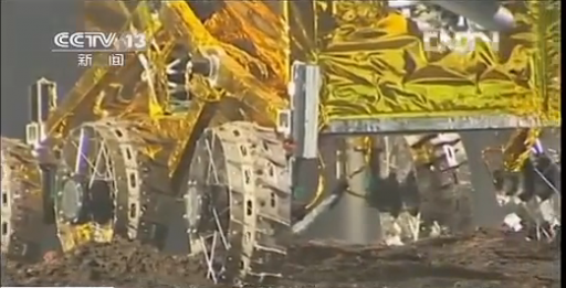
The vehicle features rockers on each side of the suspension system that are connected to each other and the rover chassis through a differential. This technique allows the rover to maintain balance – when one rocker goes up because the vehicle driving over a small obstacle, the other side goes down. One end of a rocker is outfitted with a wheel while the other is pivoted to a bogie.
This design allows the rover to climb over obstacles while keeping all six wheels on the ground. The tilt stability of the rover depends on the height of its center of gravity.
This six rover wheels are individually powered by six brushless DC motors. According to computer animations showing the rover, steering motors are used on the front and rear wheels which would allow the rover to turn in place. Each wheel has cleats that provide grip when driving through the fine lunar regolith.
The Chang’e 3 rover can tolerate slopes of up to 20 degrees and drive over obstacles of up to 20 centimeters. Overall, the rover has been conceptualized for a total driving distance of up to 10 Kilometers.
Rover Control & Navigation
The Chang’e 3 rover uses an onboard Delaunay algorithm that analyzes imagery acquired by the Navigation and Hazard Avoidance Cameras in real time using a stereo imagery analysis tool. This way, the rover is able to recognize obstacles and hazards that are automatically avoided. Furthermore, the rover is able to identify driving targets and autonomously plan the path towards the target location constantly determining its own attitude using its onboard sensors and identifying its relative position using real-time imagery.
Rover teleoperation from the ground is also planned to be utilized. The signal delay for a two-way trip from the Moon and back is 2.5 seconds allowing near real-time interactions with the rover and insight into its performance on the surface.
Rover Instruments
Ground Penetrating Radar
Mounted on the underside of the Chang’e 3 rover is a radar payload for studies of the lunar subsurface to a depth of lunar soil of 30 meters and a depth of at least 100 meters in the lunar crust structure. Determining the sub-surface structure to these depths allows studies of the geologic and thermal history of the Moon and assessments of the quantity of potential resources for future lunar exploration.
Radar payloads have flown on a number of lunar orbiters and have provided data on the global and regional regolith thickness and the deeper structure of the Moon using geophysical models. In-situ measurements are desired to validate the models that were used and confirm the conclusions of those orbital measurements.
The Chang’e 3 Ground Penetrating Radar is going to examine the shallow subsurface to better characterize surface geology, structure and dielectric properties.
Proposed for the mission was a dual-frequency Ground Penetrating Radar operating at frequencies of 500 MHz and 60 MHz to provide a combination of deep penetrations depths and high subsurface resolution. The GPR provides a penetration depth of 2 to 50 meters for maria and >100 meters for highlands. The high frequency band provides data with a range resolution of 20 to 25 centimeters while the low frequency band is limited to a resolution of 2 to 2.5 meters.
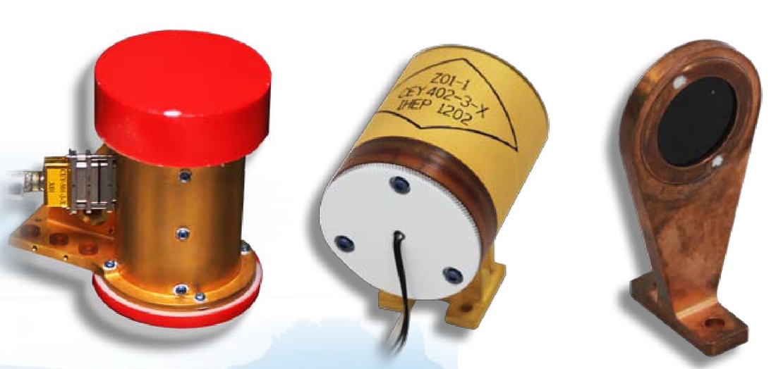
Alpha Particle X-Ray Spectrometer
Installed on the robotic arm of the Chang’e 3 rover is an APXS payload. More correctly, the APXS sensor head is installed on the robotic arm while the electronics box resides inside the rover body. Survival of APXS during lunar night is ensured by a radioisotope heater unit.
APXS utilizes a combination of methods to determine elemental chemistry of regolith and rocks. Those methods include Particle-Induced X-Ray Emission and X-Ray Fluorescence. The instrument uses a 30 Millicurie radiation source for X-Ray spectroscopy to reveal the abundance of major elements down to trace elements.
Measurements are performed by deploying the sensor towards a chosen sample & placing the sensor at a close distance to the target using the robotic arm.
When colliding with an atomic nucleus of the target, alpha particles are backscattered to the instrument detector which can measure the energy of the particle. Knowing the initial energy and the characteristic energy after the collision taking into account the physical laws of Rutherford backscattering allows the calculation of the mass of the nucleus that participated in the collision.
Light elements absorb more energy while heavy elements reflect alpha particles with nearly the same energy. Creating a spectrum of the energy of the scattered alpha particles allows scientists to determine the chemical composition of the target. Due to the low backscattering rate, long APXS integrations are required for precise measurements.
When colliding with atoms, alpha particles can also eject electrons from the inner shell of those atoms. These shells are then filled with higher-energy electrons from outer shells resulting in the emission of an x-ray with an energy matching the energy difference between the two shells. This Particle-Induced X-Ray Emission is also used by APXS.
Chang’e 3 usually uses 30-minute APXS integrations for a single target. Calibration is accomplished by measuring a calibration sample that is installed on the rover and is of a known composition following extensive ground testing with lab-equipment and the flight unit APXS.
The main objective of the Instrument is to characterize the geological context of the rover’s environment and to investigate the processes that formed the rocks and soil as well as other geological features. With new analysis tools, APXS data can also be used to derive normative mineralogy and the abundance of X-Ray invisible components for example bound water or carbonates when present in large quantities.
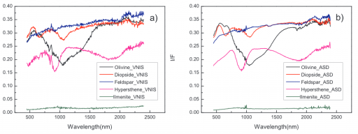
VIS/NIR Imaging Spectrometer
The Visible/Near-Infrared Imaging Spectrometer is installed beneath the rover’s top deck to make in-situ measurements of lunar minerals and resources distribution. The instrument covers a spectral range of 0.45 to 2.4 micrometers allowing the instrument to detect lunar minerals and measure abundances with a maximum spectral uncertainty of 10%. It is the first such payload to be used on a lunar rover.
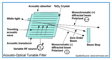
The instrument uses an Acousto-Optic Tunable Filter design. An AOTF is an electro-optical device that serves as an electronically tunable spectral bandpass filter with no moving parts. It uses a crystal in which Radio Frequency Waves are used to separate a single wavelength of light from a broadband source. The output wavelength is a function of the RF frequency that is applied to the crystal which can be varied.
Usually, an oscillating electrical signal is used to drive the piezo-electric transducer that vibrates to create acoustic waves in the crystal which change the index of refraction of the material so that incoming light scatters. (The crystal lattice is alternately compressed and relaxed which allows the medium to act like a diffraction grating but with the advantage of only diffracting one specific wavelength that is selected by altering the RF.) Beam stops are implemented to block the zero-order beam and one of the polarized first-order beams to direct the first-order beam with the desired polarization to the experiment.
A commonly used crystal is Tellurium Dioxide that provides a high transmission efficiency.
Within the spectrometer, the AOTF acts as the monochromator. This design provides a number of advantages including long-term wavelength repeatability, extremely high wavelength purity, fast response to RF changes so that spectra can be recorded within seconds, high efficiency and long service life (no moving parts).
The intensity of reflected light at each selected wavelength is detected to create the VIS/NIR spectra that are used to determine target composition and mineral abundance.
The Chang’e 3 VIS/NIR Imaging Spectrometer has a field of view of 6 by 6 degrees for the visible spectrum and 3 by 3 degrees for the NIR band. The instrument achieves a spectral resolution of under 8 nanometers for the 450-950nm band, and under 12nm for the 900-2400nm band using a continuously tunable RF frequency of 40 to 180 MHz.
Panoramic Cameras
Installed on the mast of the Chang’e 3 rover are two panoramic cameras. The distance between the two cameras is well defined and to allow the system to acquire high-resolution stereo images for three-dimensional imaging.
The PanCams can focus from 3 meters to infinity using manual and automatic focus capability. Field brightness is automatically adjusted.
Imagery provided by the cameras is used to assess the lunar surface morphology and topography around the rover. The cameras also provide mission support including digital terrain modeling. Imagery is also used by mission planners to identify safe traverse routes and identify targets for contact science.
Engineering Cameras
Just like the Mars rovers used by NASA, China’s Chang’e 3 rover uses a series of engineering cameras that are installed on strategic positions on the rover vehicle. Two navigation cameras are installed on the mast and two Hazard Avoidance Cameras are installed on the lower front portion of the rover (rear-facing cameras are not mentioned).
.
Mission Design
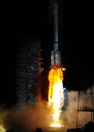
Chang’e 3 is set to launch from the Xichang Satellite Launch Center atop a Long March 3B rocket that features a number of modifications for this particular mission. Liftoff occurs on December 1, 2013 and the launch vehicle inserts the vehicle into a Trans-Lunar Trajectory for a 5-day cruise. During the cruise, a number of trajectory corrections are performed.
Lunar Orbit Insertion occurs on December 6 followed by an orbit adjust maneuver several days later. Landing is planned to occur on December 14 and is a complex 7-step sequence that delivers the 1,200 Kilogram lander & rover to the surface of Sinus Iridum.
https://www.youtube.com/watch?v=hUW0ippVNL4
Launch Vehicle & Ascent Phase

The Long March 3B launch vehicle is the heavy-lifter in China’s fleet of Long March (CZ) rockets. It is based on the CZ-2E and 3A launch vehicles featuring additional boosters. Long March 3B stands 54.84 meters tall and has a main diameter of 3.35 meters with a total liftoff mass of 425,800 Kilograms. The vehicle is a three-stage launcher that has four liquid-fueled boosters clustered around its first stage. The boosters, first and second stage use storable propellants, Unsymmetrical Dimethylhydrazine and Nitrogen Tetroxide while the third stage uses cryogenic propellants, Liquid Hydrogen and Liquid Oxygen.
CZ-3B can deliver payload of up to 12 metric tons into Low Earth Orbit, 5,100 Kilograms into Geostationary Transfer Orbit and 3,300 Kilograms into Heliocentric Orbit.
>>>Launch Vehicle Overview
On Launch Day, the Long March 3B goes through a seven-hour countdown procedure that includes extensive launch vehicle checkouts and the cryogenic tanking sequence. The boosters, first and second stage are filled with storable propellants several days ahead of launch.
Long March 3B uses four liquid-fueled boosters that are attached to the first stage to provide extra thrust during the initial portion of the flight. Each booster is 15.33 meters long and 2.25 meters in diameter, using a single DaFY-5-1 engine which is an YF-20-type engine that provides 740.4 Kilonewtons (75,500 Kilogram-force) of sea level thrust. The boosters burn for 125 seconds after which they are separated, consuming a total of 37,746kg of propellants.
The large first stage of the Long March 3B is 23.27 meters long and 3.35 meters in diameter, carrying a propellant load of 171,775 Kilograms. First stage propulsion is provided by a DaFY-6-2 engine which is a cluster of four DaFY-5-1 engines that are also used on the boosters.
The four engines provide a total sea level thrust of 2961.6 Kilonewtons (302,000 Kilogram-force). Vehicle control during first stage flight is accomplished by individually gimbaling the four engines. The first stage has a burn time of 146 seconds.
Following hot-staging, the second stage is in charge of powered flight. Being 9.94 meters long, the second stage is loaded with 49,605 Kilograms of propellants that are consumed by a single DaFY-20-1 main engine and a four-chamber DaFY-21-1 vernier engine.
The main engine delivers 742 Kilonewtons of thrust (75,660 Kilogram-force). The four chambers of the vernier engine, each with a thrust output of 11.8kN, are gimbaled for three-axis control. The second stage main engine burns for 178 seconds while the verniers burn 6 seconds longer to accommodate the hot staging. While the second stage is burning, the vehicle jettisons its protective payload fairing, exposing the Chang’e 3 vehicle for the remainder of its ascent.
The separation between the second and third stage is accomplished using pyrotechnics and retrorockets on the second stage. Once the second stage is at a safe distance, the third stage ignites.
Long March 3B uses a cryogenic upper stage that provides re-ignition capability to perform GTO or interplanetary insertions. Overall, the stage is 12.38 meters long with a reduced diameter of 3.0 meters. The third stage carries a total propellant load of 18,193 Kilograms of Liquid Hydrogen and Liquid Oxygen. The third stage is equipped with an YF-75 cluster of two cryogenic main engines providing a total vacuum thrust of 156.9 Kilonewtons (1,600 Kilogram-force).
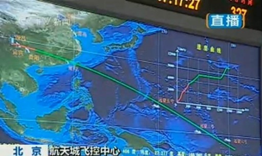
To insert Chang’e 3 into its desired Trans-Lunar Trajectory, the third stage of the CZ-3B performs a two-burn flight profile. The first burn occurs just after separation from the second stage to boost the stack into a Parking Orbit around Earth.
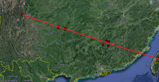
Following a short coast phase to set up the proper TLI insertion conditions, the third stage ignites on the second burn that is about three minutes in duration and delivers the stack to the desired Trans-Lunar Trajectory. After a re-orientation of the third stage, the Chang’e 3 spacecraft is released. Live telemetry coverage of all downrange events is provided by Chinese ground stations and tracking ships that are deployed in the Pacific right beneath the launch ground track.
The Long March 3B launching the Chang’e 3 probe features a number of modifications implemented for this particular mission. The LV Guidance Platform has been improved to use satellite navigation signals in addition to data from its inertial Guidance Platform to perform real-time trajectory optimization.
Also, the CZ-3B features additional cameras to provide engineering imagery of significant events such as engine burns and fairing separation.
To increase the reliability of the launch vehicle, additional measures were implemented during production and testing, increasing the statistical reliability by 0.4%.
The payload separation system has also been modified using a new type of payload dispenser that is taller than previously used adapters and includes improved payload separation mechanisms. The CZ-3B launch performance has also been improved by 30 Kilograms to 3,780kg which represents a good clue on Chang’e 3’s actual launch mass.
Not directly a launch vehicle improvement but a significant step is the implementation of real-time flight software modifications and upload capability for the Long March launch vehicle. This allows the launch period and launch window to be widened. Previous Chinese moon missions had instantaneous windows . Chang’e 3 has a launch period of 3 to 4 days every month with two launch windows per day.
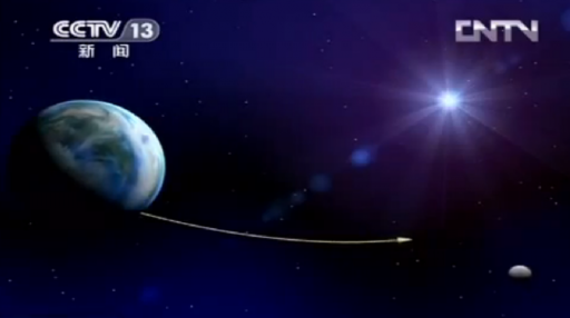
Trans-Lunar Flight & Orbit Insertion
The Long March 3B launch vehicle delivers the Chang’e 3 spacecraft to a Trans-Lunar Trajectory that takes the vehicle from Earth to the Moon in approximately five days. Following separation from the rocket, Chang’e 3 establishes three axis control and begins communications with Chinese ground stations to allow the Mission Team to begin vehicle activations and checkouts.
In depictions of the mission, the Chang’e 3 spacecraft is seen flying with deployed solar panels from Earth to Moon, but landing with stowed panels. This suggests that the panels are deployed shortly after insertion and are folded up again in preparation for landing followed by re-deployment on the surface of the Moon.
Tracking of the spacecraft is accomplished via two Chinese ground stations – a 65-meter dish in Jiamusi, northeast China and a 35-meter antenna in Kashgar, Xinjiang, northwest China. Tracking of the Chang’e 3 spacecraft provides precise trajectory data that is used to calculate Trajectory Correction Maneuvers.
Two TCMs are planned for Chang’e 3 – one during early Cruise about one day after launch and the second shortly before Lunar Orbit Insertion to set up the proper periselene altitude and location. A third TCM may be performed between the two maneuvers if deemed necessary by trajectory planners.
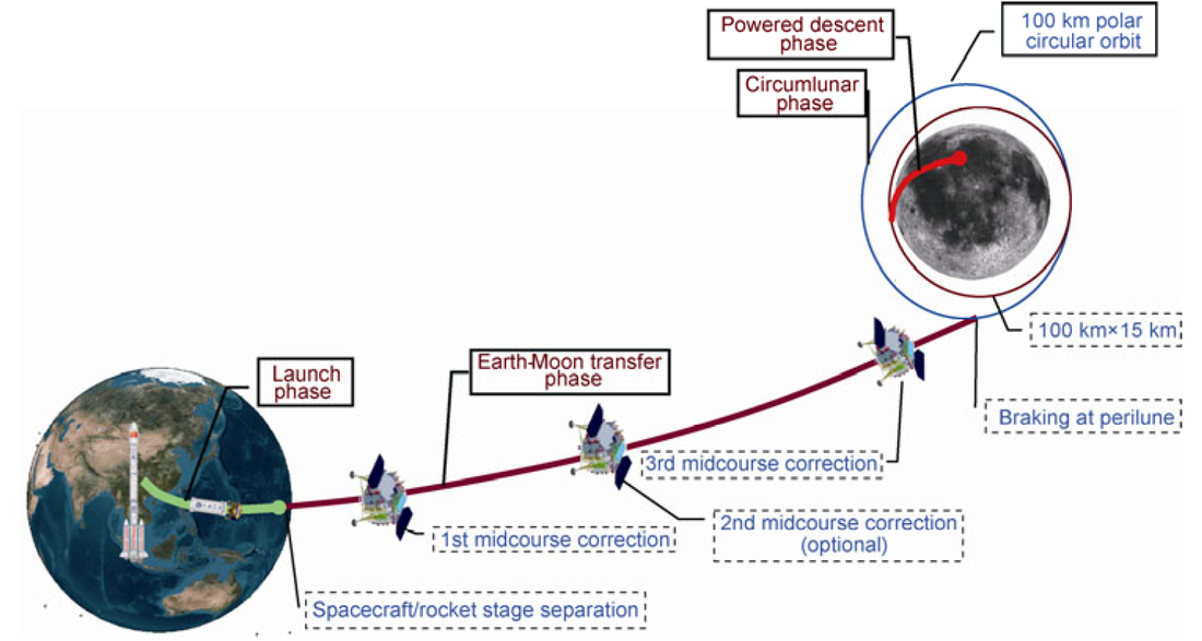
As Chang’e 3 approaches periselene, its closest approach to the Moon in its transfer trajectory, the vehicle performs its crucial orbit insertion burn. The Lunar Orbit Insertion burn takes place on December 6, 2013 (UTC).
Details on the burn procedure have not been disclosed. It seems feasible that Chang’e could either use its eight 150N thrusters to perform a longer insertion burn with high accuracy or make a shorter more efficient burn using the large main engine that can be throttled from 1,500 to 7,500 Newtons.
The spacecraft is targeting a 100-Kilometer polar orbit around the Moon. Whether the vehicle uses a two-burn insertion profile or a single burn with one or two clean-up maneuvers is not known.
Orbital Phase & Landing Timing
Once achieving its initial 100-Kilometer orbit around the Moon, Chang’e 3 starts a ten-day mission phase in orbit around the Moon. This phase likely features LOI clean up maneuvers and smaller orbital adjustments to start targeting the landing site. Also, vehicle checks are likely to continue in lunar orbit.
At some point before landing, Chang’e 3 performs an orbit adjustment maneuver that places the vehicle in an orbit of 15 by 100 Kilometers around the Moon with the periselene location carefully position to line up with the landing site on December 14 for the ambitious landing maneuver.
The timing of landing has been carefully chosen considering the important factor of sunlight. With lunar days and nights of 14 days, it is highly desirable to perform the landing early in the lunar day at the landing site so that the lander & rover could operate for the first two weeks of the mission in daylight. There are no guarantees that either can survive the first lunar night so performing initial science operations in the first few days after landing ensures that at least some scientific and engineering data is gathered.
Sunrise at Sinus Iridum occurs on December 14 and landing later that day ensures that there is enough light for solar power generation, descent photos and initial photos to be taken at the landing site. After landing, the lander & rover are in constant sunlight for almost 14 days to allow initial operations to be completed before the first transition to Lunar Night Sleep Mode.
The Landing Site
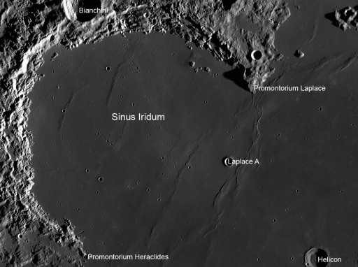
The landing site chosen for the Chang’e 3 mission is Sinus Iridum, Latin for Bay of Rainbows. It is located 44 degrees north of the lunar equator. It is a plain of basaltic lava that forms a north-west extension to Mare Imbrium. Sinus Iridum is surrounded by the Montes Jura Range. Its surface is flat without any large impact craters and slopes of no more than 7 degrees with an average slope of 2.2 degrees. The mean height of the landing site is –2,990 meters.
The landing site was chosen based on high resolution imagery and ranging data provided by the Chang’e 1 and 2 spacecraft. Chang’e 2 provided images of the area at resolutions of 7 meters and 1.5 meters (partial).
Those images show small craters and groups of boulders which have been identified to be the main concern for the soft landing. Fresh caters with sharp edges are a threat to the lander. The proposed landing area within Sinus Iridum has been chosen because of a low crater density.
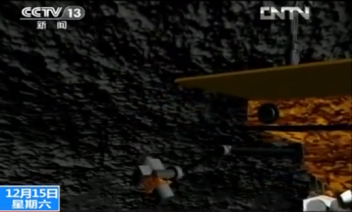
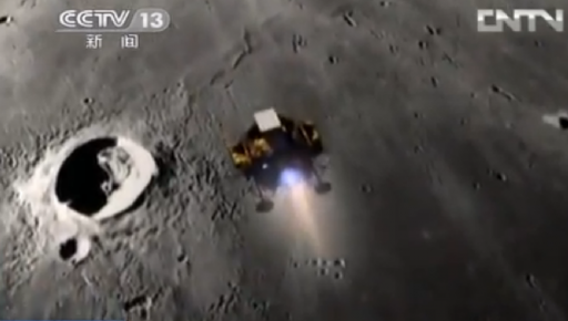
Landing Sequence
Chang’e 3 uses a seven-step landing sequence taking 700 seconds from the ignition of its main engine until touchdown at Sinus Iridum. The spacecraft is starting out in a 15 by 100-Kilometer orbit with a carefully positioned periselene position. The spacecraft is starting out in a 15 by 100-Kilometer orbit with a carefully positioned periselene position. The periselene is precisely positioned to set up a low pass downrange from the landing site to begin the landing maneuver.
Once reaching a pre-determined point downrange from the landing site, the lander begins its retrograde burn near periselene to initiate the adventurous landing sequence.
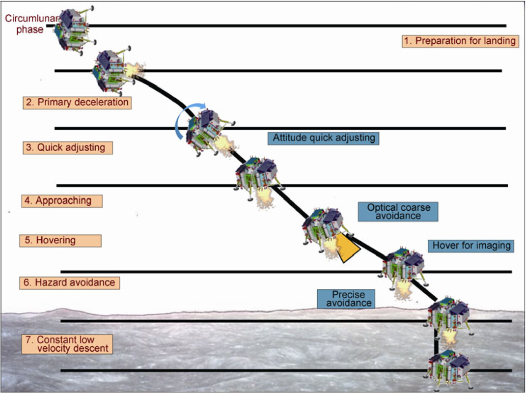
Chang’e 3 uses its throttlable main engine for one continuous burn from orbit all the way down to 4 meters above the surface. The 150N and 10N thrusters are used for attitude control and re-orientation maneuvers with quick response times. Initially, the spacecraft is flying in a retrograde altitude for the primary deceleration segment of the burn. Navigation data is provided by the lander’s inertial guidance platform, a laser ranging system and a microwave ranging sensor.
The relative orbital velocity of 1.71km/s will be flown out as Chang’e 3 drops from 15 to 2 Kilometers, making its primary deceleration burn. At a sensed velocity & at an altitude of 2 Kilometers, the lander starts the Quick Adjusting Sequence of the descent, performing attitude maneuvers as it closes in on the surface.
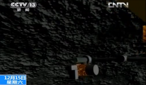
Starting at a certain altitude (between 4 and 2km), the descent camera becomes active and the spacecraft begins processing imagery and laser ranging data to automatically detect obstacles that are being avoided by altering the descent trajectory and re-scanning the new landing site. At an altitude of 100 meters, the vehicle starts a hovering segment of up to 100 seconds to acquire imagery of the landing site and perform precise avoidance maneuvers ahead of the vertical descent.
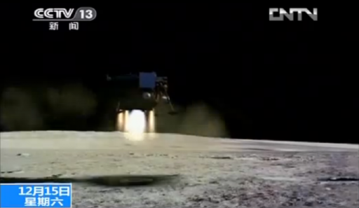
After hovering, the vehicle starts a constant low velocity descent toward the surface, constantly throttling down its engine as the vehicle gets lighter. Precise altitude data is provided by a gamma-ray altimeter that is used to provide the final engine cutoff signal.
Once the altimeter senses an altitude of four meters, the main engine is shut down and the lander drops to the surface. The shock occurring at landing is dampened by the landing legs and support struts to maintain vehicle limits.
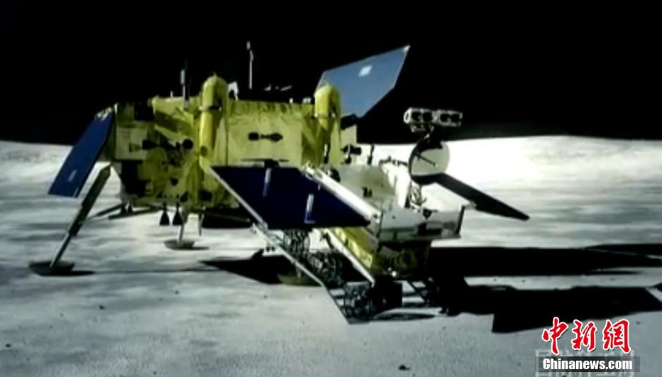
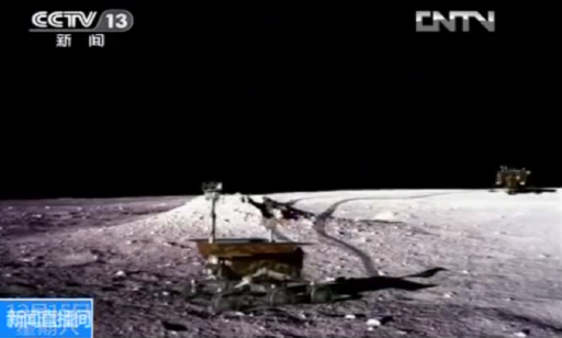
Following landing, the lander solar arrays are re-deployed and the rover is released. The Yutu rover is deployed about four hours after landing as part of a complex sequence that takes two hours. Once deployed on the surface, the rover will likely undergo a number of checkouts before making initial drives and beginning science operations one Earth day after landing as part of the first lunar day of the mission.
One day after landing, the two vehicles – the Chang’e lander and Yutu rover start a sequence of taking photos of each other before the rover departs the landing site and starts nominal mission operations.
Science operations of the lander are also expected to get underway a short time after landing to ensure the vehicle gets as much out of its first lunar day as possible.
Mission Operations
The Chang’e 3 lander is expected to perform a science mission of a least one year, being built to survive several lunar nights to facilitate a number of observation campaigns using its Ultraviolet imaging payloads.
The rover is expected to operate for three months on the lunar surface, being designed to survive at least three lunar nights. It is designed to drive a total distance of up to ten Kilometers to explore an area of three square Kilometers. Both vehicles, the rover and lander, are equipped with independent communications systems for data relay to Earth and command reception.
LADEE & Chang’e 3
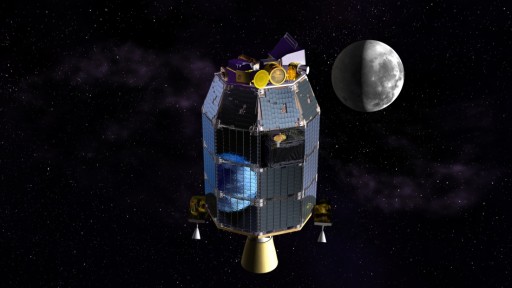
When Chang’e 3 arrives at the Moon to begin its adventurous landing, NASA’s LADEE spacecraft is in the midst of its science mission, orbiting the Moon in a low orbit of 40 to 100 Kilometers to study the lunar exosphere.
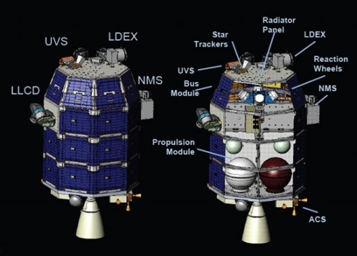
Carrying three instruments, LADEE explores the Moon’s thin exosphere and dust environment to answer long standing questions on the formation and evolution of exospheres. The spacecraft carries a Neutral Mass Spectrometer to measure particles in the lunar exosphere, a Ultraviolet/Visible Spectrometer to study dust by making occultation measurements and to detect a number of chemical species, and the Lunar Dust Experiment that conducts in-situ measurements to examine the local and temporal variability of dust distribution in the lunar exosphere taking into account dust grain size and density.
>>>LADEE Instrument Info
>>>LADEE Science Overview
LADEE studies the density, composition and spatial as well as temporal variability of the lunar exosphere to probe its origin and study its response to phenomena like solar wind. The mission also attempts to examine the abundance and variability of dust particles that may be present in the exosphere. Scientists want to study the lunar atmosphere in an undisturbed condition before any significant human or robotic activity disturbs the fragile exosphere.
Chang’e 3 certainly represents a significant robotic activity that disturbs the lunar exosphere which will not get unnoticed by LADEE’s instruments – presenting an operational challenge to the LADEE team, but also a great opportunity to study the response of the lunar environment to this disturbance.
As Chang’e 3 gets captured in its initial lunar orbit by making a main engine burn, the combustion products generated by the engine also end up in the lunar exosphere.
When making its descent to the surface, Chang’e 3 again releases a large quantity of combustion products and also kicks up dust into the exosphere. Particles that are being released usually travel on a parabolic trajectory (or even end up in a short-lived orbit) before being re-captured or lost into space. Gases and particles released into the atmosphere are subject to complex transportation and loss processes that are poorly understood and one of LADEE’s key objectives.
What Chang’e 3’s landing presents to the LADEE science team is a novel opportunity of performing a carefully conducted experiment to better understand exosphere dynamics such as transportation and loss processes.
Starting its primary science mission on November 20, 2013, LADEE can examine the undisturbed lunar exosphere for nearly one month to gather baseline data on this pristine environment. (LADEE inserted itself into lunar orbit in early October so that the combustion & outgassing products it introduced have largely dissipated when science operations start.)
With LADEE up and running, gathering data, Chang’e 3 arrives at the Moon – first making its orbit insertion burn, then its orbit adjust burn and the big landing maneuver which will release the majority of combustion products and dust.
The parameters of this ‘experiment’ are fairly well known – Chang’e 3 releases a known quantity of gas of known composition at a precisely defined time and location.
Using Unsymmetrical Dimethylhydrazine and Nitrogen Tetroxide propellants, Chang’e 3’s main engine adds a number of species to the exosphere – water, nitrogen, carbon monoxide and carbon dioxide as well as trace species including hydrogen and hydroxyl.
Firstly, LADEE can look at the exospheric addition to try and study the total mass gain of the lunar exosphere caused by Chang’e 3. Also, the spacecraft can be used to study distribution processes to examine how quickly the combustion products are transported within the exosphere to learn more about potential transport processes and study the eventual loss of the gases and dust particles.
The Neutral Mass Spectrometer can be used to make in-situ measurements of the released species at different positions above the lunar surface and at different altitudes of LADEE’s orbit in order to study the spatial and temporal aspects of exospheric transportation.
The Ultraviolet/Visible Spectrometer can be used in its limb-scan mode to determine the dust concentration at different altitudes to assess how much dust was added to the exosphere by the landing maneuver and which altitudes it reaches. Additionally, the instrument measures a number of atmospheric species including water and OH so that a before-and-after comparison of concentrations will be possible as well as close monitoring of the temporal evolution of the concentration of those species.
LDEx, the Lunar Dust Experiment, is able to make in-situ measurements of the dust environment at LADEE’s orbital altitude. The instrument can be used to measure the increase in dust detections as a result of the landing and also look at the variation of dust particle sizes to determine which particles remain captured in the exosphere the longest to provide additional data on transport and loss processes.
After Chang’e 3’s landing, LADEE’s instruments are used to study how the distribution of gases and dust evolves over time and when the exosphere returns to its initial state.
None of this was pre-arranged between the US and China. The landing of Change provides a great opportunity to enhance the scientific results provided by the LADEE mission, shedding light on the poorly understood process ongoing in the lunar exosphere and the external processes that influence it.
