
Atlas V 551
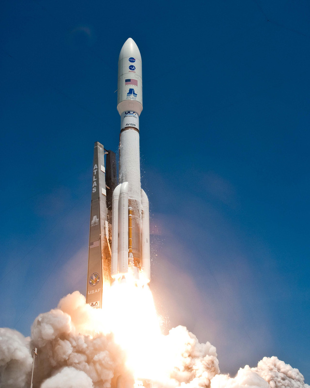
The Atlas V 551 Launch Vehicle is a part of the flight proven Atlas V 400/500 family that is being operated by United Launch Alliance. Atlas V rockets are flown since 2002 and have a near-perfect success rate (one flight was a partial failure, however the mission was catalogued as a success).
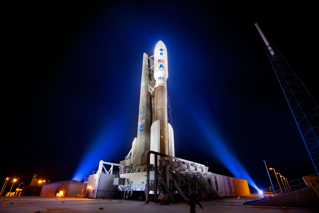
The Vehicle is operated from Launch Complex 41 at the Cape Canaveral Air Force Station, Florida and Launch Complex 3E at Vandenberg Air Force Base, California. The vehicle is assembled in Decatur, Alabama; Harlingen, Texas; San Diego, California; and at United Launch Alliance’s headquarters near Denver, Colorado.
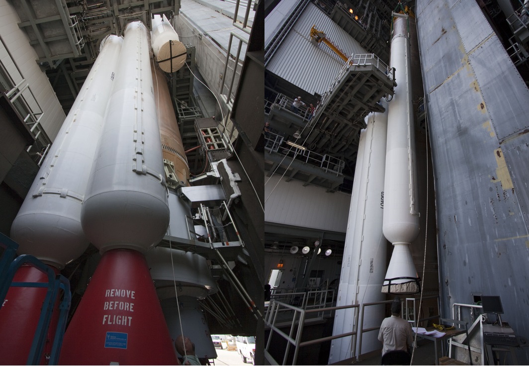
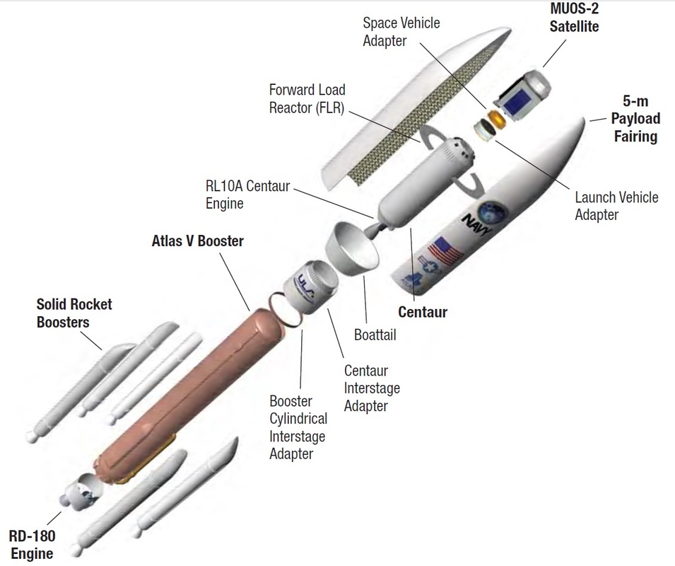
Atlas V 551 is the largest of the Atlas V Launcher Family flown to date featuring five Solid Rocket Boosters and a 5.4-meter Payload Fairing. The 551 configuration has two stages, a Common Core Booster and a Centaur Upper Stage. Centaur can make multiple burns to deliver payloads to a variety of orbits including Low Earth Orbit, Geostationary Transfer Orbit and Geostationary Orbit as well as Earth Escape Trajectories.
Notable Payloads launched by the 551 version include NASA’s New Horizons (2006) and Juno Spacecraft (2011) as well as the US Navy’s MUOS Satellite Fleet.
Every Atlas V version has a three digit ID-Number:
First Digit: Payload Fairing diameter: 4XX – 4m Diameter; 5XX – 5.4m Diameter
Second Digit: Number of Solid Rocket Boosters (0-5)
Third Digit: Number of RL-10A Engines on Centaur (1 or 2)
| Type | Atlas V 551 |
| Height | 62.2m |
| Diameter | 3.81m |
| Launch Mass | 587,000kg |
| Stage 1 | Atlas Common Core Booster |
| Boosters | Five |
| Span | 6.9m |
| Stage 2 | Centaur |
| Mass to LEO | 18,500kg |
| Mass to SSO | 13,500kg |
| Mass to GTO | 8,700kg |
| Mass to GEO | 3,960kg |
Atlas V 551 Specifications.
Atlas V 551 stands 62.2 meters tall and has a main diameter of 3.81 meters. With a liftoff mass of 587,000 Kilograms, it is the heavy-weight of the SEC (Single Engine Centaur) Atlas V Fleet as the 551 version features five Solid Rocket Boosters.
The Launcher uses the conventional Atlas V design with a Common Core Booster and a Centaur Upper Stage on top of it.
Atlas V 551 features a 5.4-meter payload Fairing under which it can carry payloads of up to 18,500 Kilograms to Low Earth Orbit.
Geostationary Transfer Orbit Capability is 8,700 Kilograms. Direct GEO Injections of Payloads up to 3,960kg are also possible.
.
Common Core Booster
| Type | Common Core Booster |
| Inert Mass | 21,054kg |
| Diameter | 3.81m |
| Length | 32.46m |
| Propellant | Rocket Propellant-1 (Kerosene) |
| Oxidizer | Liquid Oxygen |
| Fuel&Oxidizer Mass | 284,089kg |
| Guidance | From Centaur |
| Propulsion | RD-180 Engine (2 Chambers) |
| Type | Staged Combustion |
| Thrust at Sea Level | 3,827kN |
| Isp SL | 311s |
| Thrust (Vacuum) | 4,152kN (933,369 lbf) |
| Isp Vac | 338s |
| Engine Length | 3.56m |
| Engine Diameter | 3.15m |
| Engine Dry Weight | 5,480kg |
| Chamber Pressure | 266.8bar |
| Nozzle Ratio | 36.87 |
| Thrust to Weight | 78.22 |
| Area Ratio | 36.4 |
| Ox. To Fuel Ratio | 2.72 |
| Attitude Control | Gimbaled Engine (8 Degrees) |
| Throttle Capability | 50-100% |
| Burn Time | 253 sec |
| Tank Pressurization | Helium |
| Avionics | Flight Control, Flight Termination |
| Telemetry, Rate Gyros, Power | |
| Stage Separation | 8 Retro Rockets |
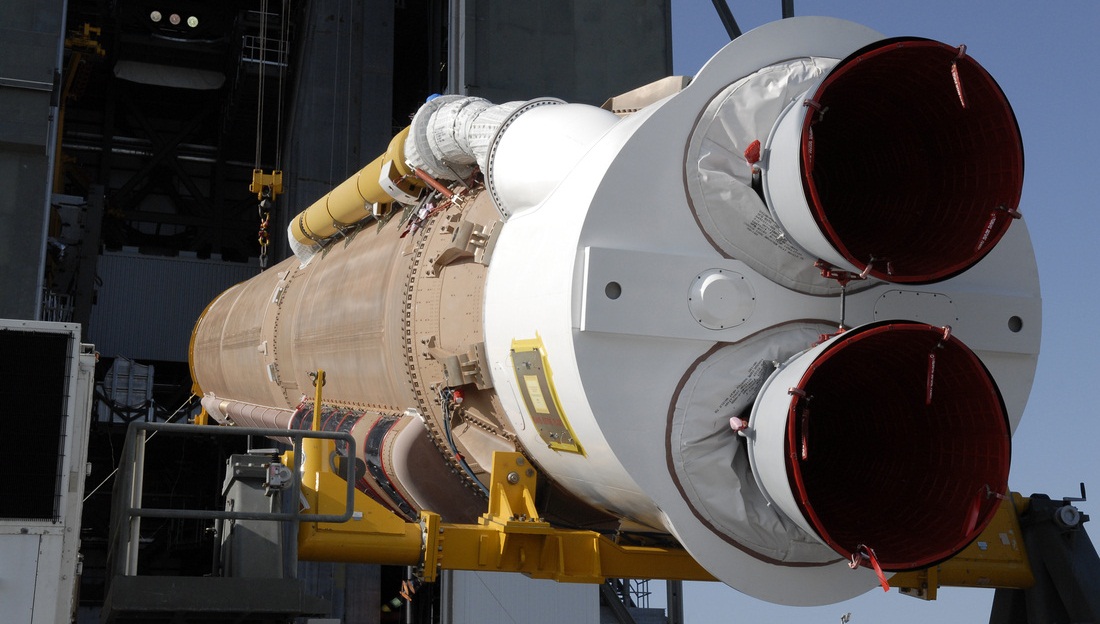
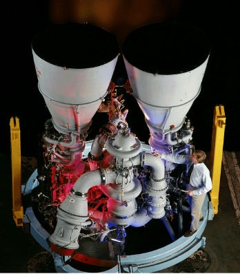
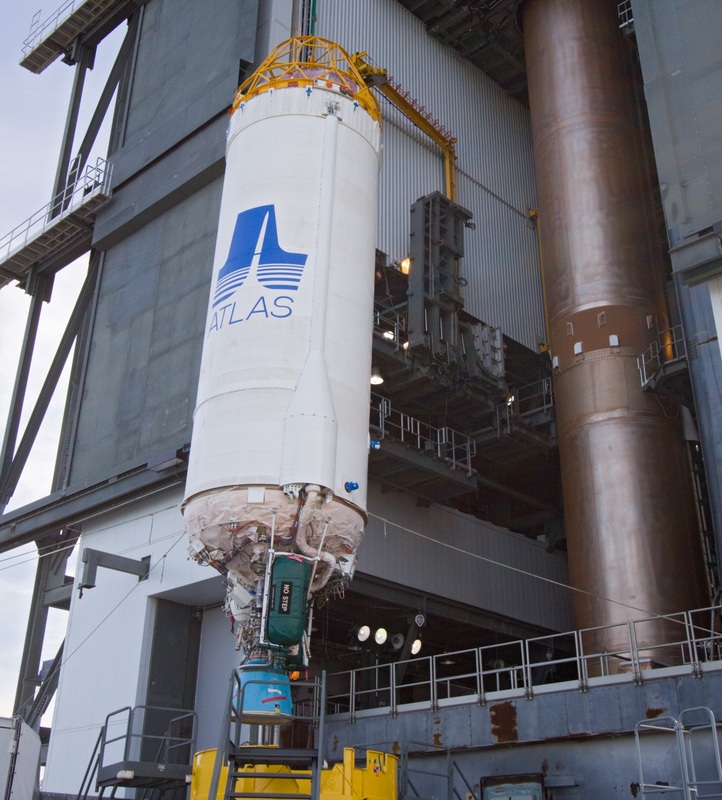
The first Stage of the Atlas V 551 is an Atlas Common Core Booster that is 32.46 meters long and has a diameter of 3.81 meters. With an inert mass of 21,054 Kilograms, the Common Core booster can hold up to 284,089 Kilograms of Rocket Propellant-1 and Liquid Oxygen that are consumed by the single RD-180 Main Engine of the vehicle.
RD-180 is being manufactured by NPO Energomash. It is a two-chamber staged combustion engine that provides 3,827 Kilonewtons of liftoff thrust and 4,152 Kilonewtons of vacuum thrust. RD-180 maintains a high-pressure staged combustion cycle employing an Oxygen-rich preburner. It runs with an oxidizer to fuel ratio of 2.72.
The drawback of an oxygen-rich combustion is that high pressure, high temperature gaseous oxygen must be transported throughout the engine. The nominal chamber pressure is 267 bar.
RD-180 is capable of being throttled from 50% to 100% of rated performance. The engine is based on the RD-170 engine that features four combustion chambers. First Stage control is accomplished by gimbaling the RD-180 nozzles by up to 8 degrees. Engine gimbaling is achieved via the vehicle’s hydraulics system.
The first stage propellants are held inside aluminum isogrid tanks; tank pressurization is accomplished with high-pressure Helium that is stored in Helium Bottles on the Common Core Booster. Tank pressurization is computer-controlled. The Common Core Booster is equipped with a Flight Termination System that can be used to destroy the vehicle in the event of any major malfunction.
Also, the CCB is outfitted with redundant Rate Gyros to acquire navigation data. Internal Batteries provide power during powered ascent and an independent telemetry system is utilized for data downlink. First stage separation is initiated by pyrotechnics and the core stage ignites eight retro rockets to drop away from the launcher
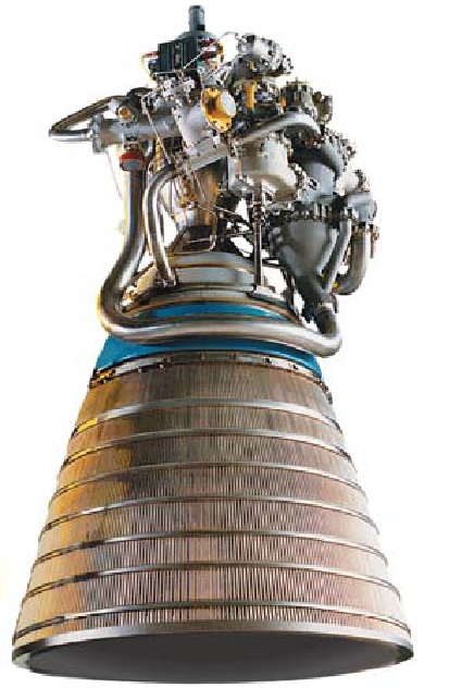
RD-180 Engine
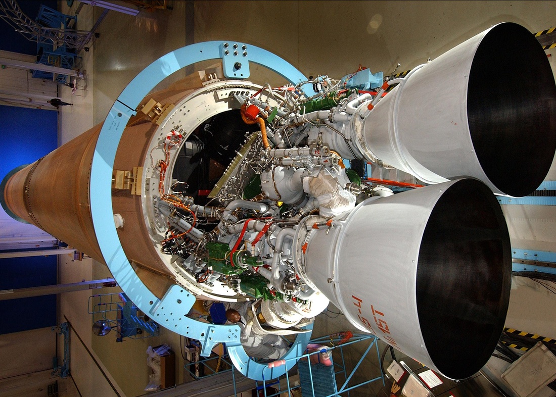
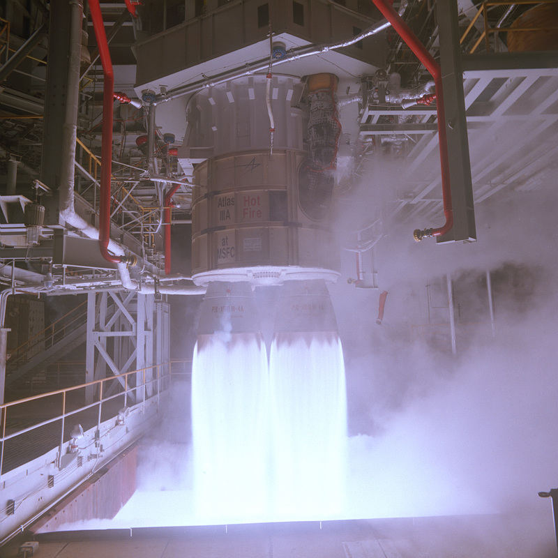
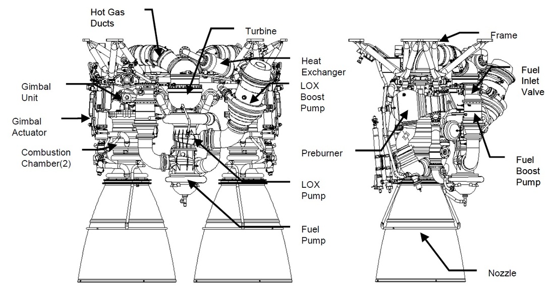
RD-180 uses a staged combustion scheme – burning all of the oxygen with little fuel inside a Gas Generator to produce a hot high-pressure gas to drive the turbine that powers the fuel and oxidizer turbopumps that feed the two combustion chambers. The engine features boost pumps at the fuel and oxidizer inlets that operate at a lower speed than the main pumps and create an engine inlet pressure sufficient for the operation of the turbopumps. The fuel boost pump is powered by a turbine driven by the fuel tapoff from one main pump (fuel returns to the inlet) and the oxidizer boost pump turbine is driven by a fraction of the hot gas from the gas generator that then enters the LOX flow and condenses.
All of the oxygen is then directed to the LOX impeller turbopump before reaching the Gas Generator. The Kerosene flow is directed into two portions using a two-stage turbopump. The Kerosene flow from the second pump stage (about 20% of total flow) is directed into the Gas Generator were it is burned in an excess of oxidizer, creating a high-pressure, oxygen-rich gas that drives the turbine. The RD-180’s LOX turbopump and fuel pumps are mounted on a single shaft. The turbine itself is a axial turbine using relatively thick blades and large clearance between the gas inlet and the blades to reduce the risk of damage. Nickel-alloys are used to endure the hot temperatures of the gas from the generator and the turbine uses cold oxygen for additional cooling.
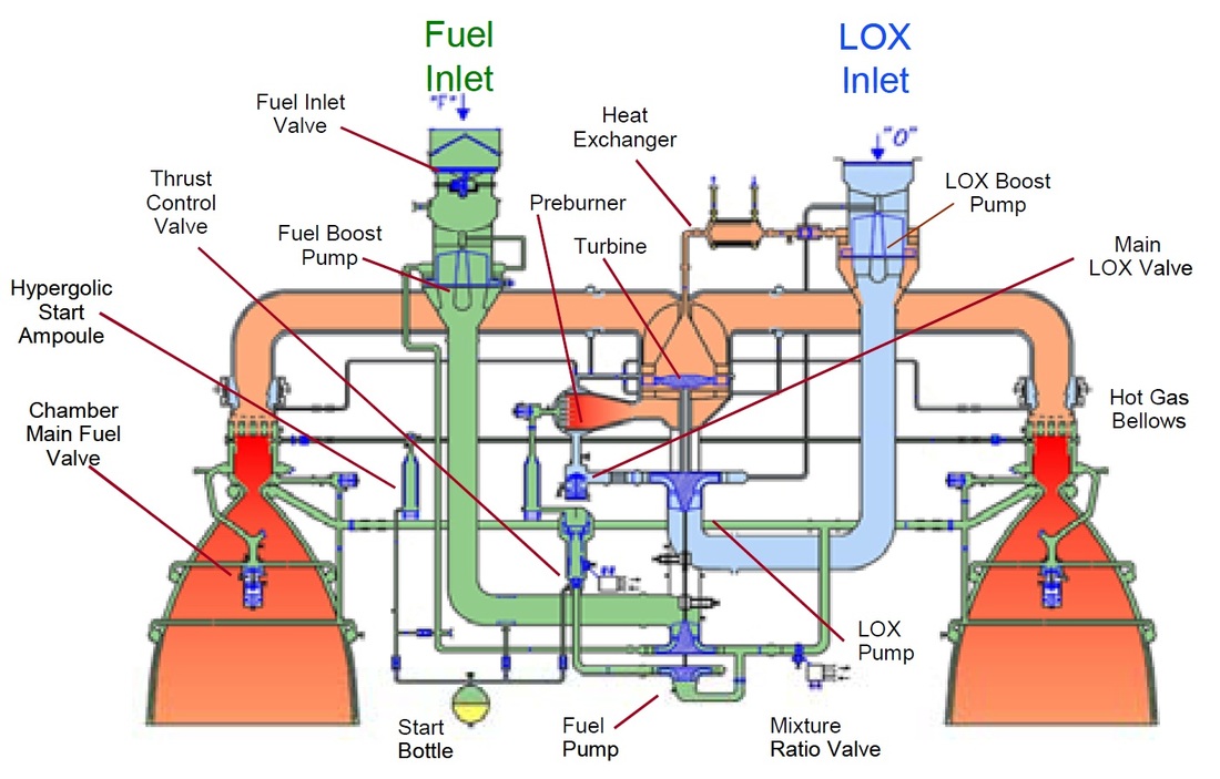
The Kerosene from the first stage pump is directed to the combustion chamber and nozzle where it passes through heat exchangers as part of the regenerative cooling scheme of the engine. The engine uses three cooling paths, one entering at the combustion chamber, one entering at the nozzle throat and the third one entering at the nozzle exit. After passing through the heat exchangers, the fuel is pumped into the combustion chamber where it is burned by the oxygen-rich gas coming from the gas generator. The mixture ratio is adjusted by a mixing valve located behind the first stage turbopump and the Gas Generator Temperature and engine thrust are regulated via flow valves ahead of the Gas Generator. RD-180 has a nominal mixture ratio of 2.72.
RD-180’s chamber consists of the mixing head, the combustion chamber and the nozzle. The injector uses small nozzles through which the components are introduced into the combustion chamber, forming a circular inner zone separated from an outer ring by protruding nozzles. The outer ring is divided into six compartments using protruding nozzles through which propellants enter the chamber. Fuel and oxidizer-rich gas alternates between the seven compartments. This design allows a stable combustion and avoids combustion instability or the creation of hot spots. RD-180 operates at a nominal chamber pressure of 266.8 bar.
RD-180 uses a chemical ignition system based on Triethylaluminium (TEA) – a pyrophoric substance that immediately ignites upon exposure to oxygen. The TEA is stored in closed ampoules – one in the fuel line directly ahead of the Gas Generator and one in either of the main fuel inlet to the combustion chambers. These ampoules use membranes to prevent the TEA from coming into contact with air.
For engine start, a dedicated spherical Kerosene, tank that is connected to both fuel lines via plumbing and associated valves, is filled with fuel and pressurized using high-pressure gas. Once the valves to the fuel lines and ampoules are opened, the high-pressure fuel drives pistons that are part of the ampoules to create a pressure inside the cavity that causes the TEA to be released into the Gas Generator and combustion chamber that have been filled with oxygen by that point after LOX valves are opened and the tank pressure causes oxygen to enter the engine.
Coming into contact with oxygen, the TEA ignites and starts the combustion process inside the Gas Generator and the main chamber. The combustion is sustained by Kerosene entering the GG and combustion chamber right after the TEA. Once the Gas Generator is running, the turbine spins up to speed and the turbo and boost pumps begin pumping propellants to the Gas Generator and Combustion Chamber, thus sustaining the combustion process.
Using this ignition technique means that RD-180 can only be ignited once and requires extensive refurbishment after each ignition (replacing the TEA membranes and re-filling the ampoules).
For tank pressurization, Helium flows from the Helium spheres inside the LOX tank down to the engine compartment where it is heated up inside a heat exchanger connected to the hot gas flow from the Gas Generator to the LOX Boost Pump. The pressurized heated Helium is then pressed into the LOX and Kerosene tanks to keep them at the proper pressure via a series of valves that control the pressurization. The initial pre-flight pressurization is accomplished using pressurized gas supplied by ground support equipment.
Being a modern engine, RD-180 includes various pressure, flow and temperature sensors that provide detailed performance data to the engine controller and flight computers. This allows a detailed monitoring of performance and extensive post flight analysis which can be useful in case of any anomalies. Also, telemetry is used in real time by the vehicle’s control system to adjust engine parameters like mixture ratio to optimize the performance of the launch vehicle via optimal propellant utilization. Additionally, engine telemetry is used to trigger launch vehicle abort modes.
Solid Rocket Boosters
| # Boosters | Five |
| Manufacturer | Aerojet |
| Ignition | Ground-Lit |
| Length | 17m |
| Diameter | 1.58m |
| Inert Mass | 5,740kg |
| Launch Mass | 46,697kg |
| Thrust | 1,688.4kN |
| Specific Impulse | 279s |
| Nozzle Cant | 3° |
| Burn Time | 94sec |
Atlas V 551 is equipped with five Aerojet Solid Rocket Boosters that are all ignited at the moment of T-0 to provide extra thrust to lift the heavy launch vehicle with a total Thrust-To-Weight Ratio of 2.18.
Each of the Boosters has an inert mass of about 5,740kg and a total fuel load of nearly 41,000kg. The Booster provides a thrust of 1,688kN – 172,200 Kilograms.
The five boosters burn for 94 seconds and are separated in a staged fashion by firing pyrotechnic initiators. First, boosters 1&2 that are installed on one side of the vehicle are separated followed about 1.5 seconds later by boosters 3,4&5.
Typically, the boosters burn out at T+94 seconds, but the vehicle holds onto the boosters for another 10 seconds for Range Safety Reasons to ensure an impact in the pre-planned off-shore area.
Interstage & Aft Stub Adapter
The first and second stage of the Atlas V launch vehicle are connected by a Interstage Adapter that is used to join the two stages of the vehicle that feature different diameters. It consists of a cylindrical section that is 3.83 meters in diameter and 0.32 meters in length. The structure consists of Aluminum and weighs 285 Kilograms.
| Type | Cylindrical Interstage Adapter |
| Diameter | 3.83m |
| Length | 0.32m |
| Mass | 285kg |
| Structure | Aluminum Machined |
| Rolled-Ring Forging |
| Type | C-ISA Adapter |
| Diameter | 3.83m |
| Length | 3.81m |
| Components | Interstage Adapter, Aft Stub Adapter |
| Boattail | |
| Mass | 2,212kg |
| Structure | Composite Sandwich, Aluminum Core |
| Graphite Epoxy Face Sheets |
Centaur Upper Stage
| Type | Centaur |
| Diameter | 3.05m |
| Length | 12.68m |
| Inert Mass | 2,243kg |
| Propellant | Liquid Hydrogen |
| Oxidizer | Liquid Oxygen |
| Fuel&Oxidizer Mass | 20,830kg |
| Guidance | Inertial |
| Propulsion | 1 RL 10A-4-2 (until 2014) |
| Thrust | 99.2kN |
| Isp Vac | 451s |
| Engine Length | 2.29m |
| Engine Diameter | 1.53m |
| Engine Dry Weight | 167kg |
| Chamber Pressure | 39bar |
| Thrust to Weight | 61 |
| Area Ratio | 84 |
| Mixture Ratio | 5.5:1 |
| Propulsion | 1 RL-10C-1 (Starting in 2014) |
| Thrust | 101.8kN |
| Isp Vac | 449.7s |
| Engine Length | 2.18m |
| Engine Diameter | 1.45m |
| Engine Dry Weight | 190kg |
| Chamber Pressure | 24bar |
| Thrust to Weight | 57 |
| Area Ratio | 130 |
| Mixture Ratio | 5.5:1 |
| Burn Time | Variable |
| Engine Start | Restartable |
| Attitude control | 4 27-N Thrusters |
| 8 40-N Thrusters | |
| Propellant | Hydrazine |
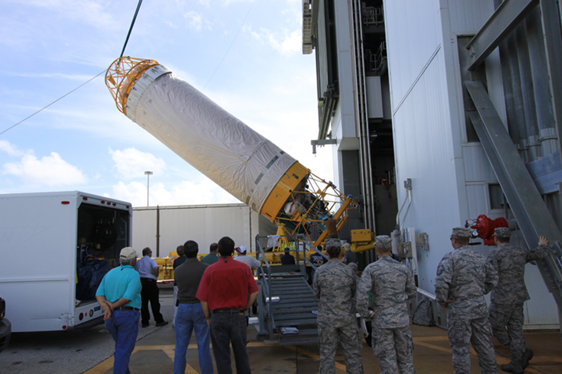
The Upper Stage of the Atlas V 551 is a single-engine Centaur Stage. Centaur is 3.05 meters in diameter and 12.68 meters in length with an inert mass of 2,243 Kilograms. Centaur is a cryogenic rocket stage using Liquid Hydrogen and Liquid Oxygen as propellants. A total of 20,830 Kilograms of propellants can be filled into the vehicle’s pressure stabilized stainless steel tanks. The LOX and LH2 Tanks are separated by a common ellipsoidal bulkhead.
Previously, Centaur was powered by an RL-10A-4-2 engine, manufactured by Aerojet Rocketdyne, providing 99.2 Kilonewtons of thrust. The engine uses an expander cycle and operates at a chamber pressure of 39 bar. RL-10 has a certified burn time of up to 740 seconds and can make multiple engine starts. It has a dry weight of 166 Kilograms and an expansion ratio of 84:1 achieving a thrust to weight ratio of 61:1. RL-10 can be gimbaled with a electromechanical system to provide vehicle control during powered flight.
Starting in 2015, all single-engine Centaur stages will transition from RL-10A-4-2 to the RL-10C-1 engine, a close relative to the RL-10A and B versions.
The engine builds on the heritage of the RL-10 engine family that can look back at a history of several decades having completed its first test in 1959 after being developed by Pratt & Whitney. Over the years, the engine underwent a number of modifications, going through several generations and being used on different launch vehicles. The RL-10A versions of the engine were used by the trusted Centaur Upper Stage, most recently in the RL-10A-4-2 variant while previous RL-10A versions were also in use aboard the Saturn I and DC-X vehicles. RL-10B-2 is used on the Delta Cryogenic Upper Stage fitted on all launchers of the Delta IV rocket family.
RL-10C uses existing RL-10B-2 engines that are part of the inventory of United Launch Alliance while RL-10A-4-2 engines had to be ordered as newly-built units from Aerojet-Rocketdyne. It is more economic to modify existing RL-10B engines with hardware adopted from the 10A version to create the RL-10C-1. Overall, the RL-10C engine has a larger operating margin than any previous RL-10 engine taking advantage of flight experience of the earlier models and a comprehensive test campaign performed by the RL-10C that demonstrated extremely long burn times and operation outside of set operating parameters.
To modify existing RL-10B-2 engines to become RL-10C-1, a number of changes are necessary such as the substitution of the extendable nozzle of the RL-10B-2 with a shorter radiatively-cooled carbon-carbon nozzle extension. Also, the RL-10B-2 needs to be outfitted with a Propellant Utilization avionics unit that controls the mixture ratio of propellant supplied to the engine for optimized propellant consumption – a feature of the Centaur’s RL-10A but not the RL-10B of the DCSS. It also includes the installation of a redundant spark ignition system that is standard on the Centaur upper stage. Aside from these changes, RL-10C employs the common turbopump and plumbing of both, RL-10A and B, but uses the chamber and injector of the RL-10B instead of the RL-10A’s unique design.
Overall, RL-10C delivers a vacuum thrust of 102 Kilonewtons, slightly more than the RL-10A-4-2 and a little less than the RL-10B-2 with its huge nozzle. The engine achieves a specific impulse of 449.7 seconds. RL-10C measures 1.45 meters in diameter and 2.18 meters in length with a total mass of 190 Kilograms. The nozzle of the RL-10C creates an expansion ratio of 130 and the engine operates at a chamber pressure of 24 bar.
During Coast Phases, the vehicle’s orientation is controlled by Centaur’s Reaction Control System. Eight lateral 40-Newton Thrusters and four 27-Newton Thrusters are used for attitude control. The System uses Hydrazine propellant. The Centaur Upper Stage houses the Atlas V Flight and Guidance Computers that are capable of autonomously performing the mission controlling all aspects of the flight. The fault-tolerant inertial navigation unit is located on the Centaur forward equipment module.
In the aft section of the Centaur Upper stage is an C-ISA – Centaur Interstage Adapter that is 3.83 meters in diameter and 3.81 meter in length. It includes three major components: Interstage Adapter, Aft Stub Adapter and Boattail. The adapter weighs 2,212kg for the single-engine upper stage.
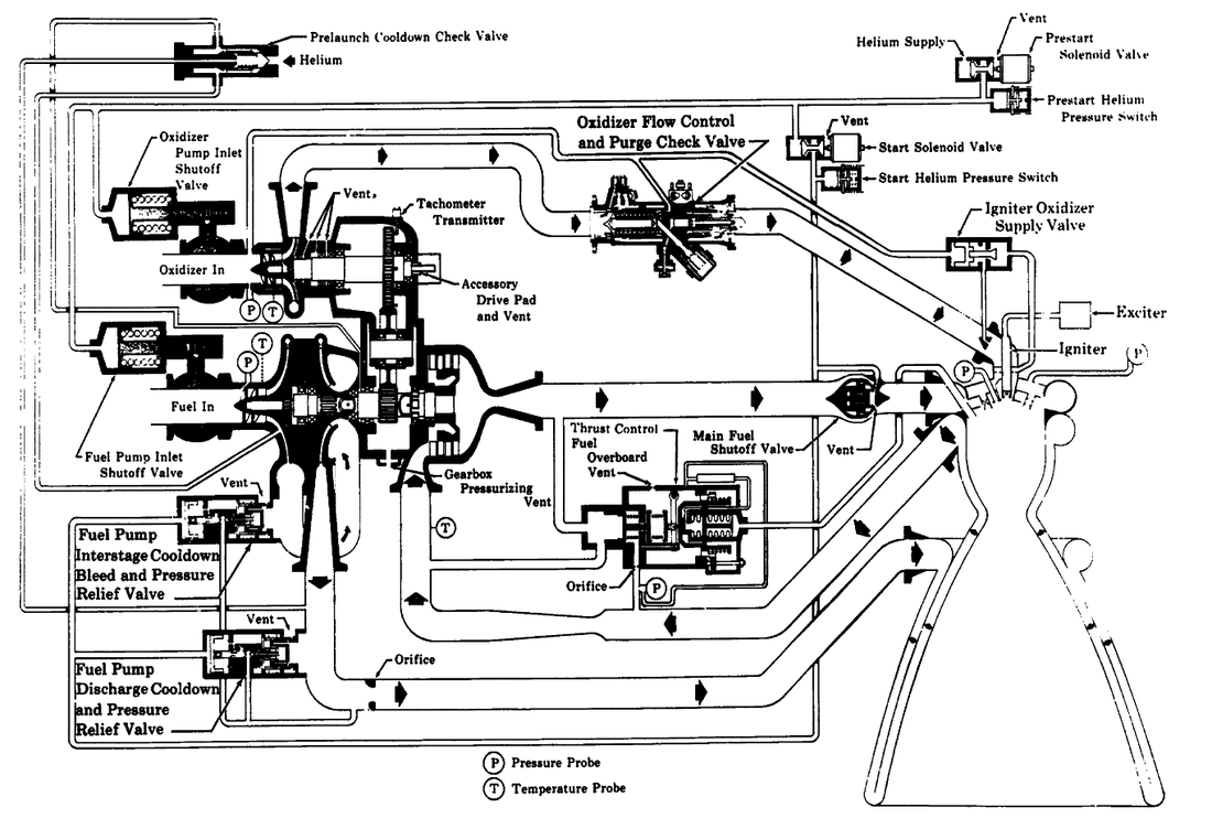
RL-10 Engine
RL-10 is a closed Expander Cycle Engine which does not rely on a gas generator to deliver the hot gas that drives the turbopump turbines of the engine. Instead, the turbines are driven by expanded hydrogen gas that is generated by running the flow of Liquid Hydrogen from the LH2 turbopump through the regenerative cooling system of the upper nozzle segment and the combustion chamber. The gasified Hydrogen then passes to the main turbine of the engine, spinning the LH2 turbopump as well as the LOX turbopump through a gearbox.
Rl-10 includes seven engine valves starting on the fuel side with the Fuel Pump Inlet Shutoff Valve and on the oxidizer side with the Oxidizer Pump Inlet Shutoff Valve. Fuel flow into the combustion chamber can be stopped by the Fuel Shutoff Valve that is located just upstream of the combustion chamber injector.
This valve is used to rapidly cut the fuel feed to the engine for shutdown and its closure also allows the chilldown of the LH2 turbopump through overboard vents without any fuel entering the chamber. Engine LH2 pump chilldown is accomplished by opening Fuel-Cool-Down Valves 1 & 2 that vent coolant overboard during chilldown. These two valves also provide fuel pump bleed during pre-start and pressure relief during shutdown.
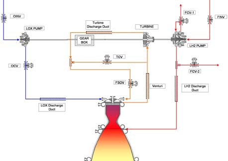
Thrust of the engine is controlled by a Thrust Control Valve located in a bridge between the fuel cooling outlet on the engine and the combustion chamber fuel inlet to bypass the turbine and thus regulate turbine power and overall engine thrust. Normally in a closed position, the system is mainly used to control thrust overshoot during engine start and to maintain a constant chamber pressure during steady state operation.
In the oxidizer line downstream of the pump is a Oxidizer Flow Control Valve that is used to regulate the LOX flow to the chamber for the regulation of the mixture ratio that is commanded by the Propellant Utilization Unit of the engine which controls the MR for an optimized propellant consumption. A second OCV is employed to regulate the bleed flow during engine start.
Engine start on the RL-10 is accomplished by using the pressure differential between the fuel feed and the near-vacuum in the chamber that forces fuel through the system after the Fuel Shutoff Valve is opened and FCV-1 is closed. FCV-2 remains in an open position to prevent stalling the LH2 pump of the engine in start-up. In the initial stages of start-up, heat from the ambient metal is sufficient to generate Hydrogen gas to start driving the turbopumps and initiate the combustion process in the chamber, heating up the chamber and nozzle to operational levels. For start, the Oxidizer Control Valve is partially closed to ensure a fuel-rich ignition, limiting chamber pressure in order to maintain a pressure differential in the fuel system until the turbopumps can accelerate.
When the pumps are at flight speed, pneumatic pressure is used to close the Fuel Cooldown Valve and open the Oxidizer Control Valve to achieve the planned LOX pump discharge properties. The opening of the OCV leads to a sharp increase in chamber pressure that can lead to thrust overshoot which is prevented by a temporary opening of the Thrust Control Valve until stable steady-state conditions are reached for engine operation.
In steady state operation, RL-10 consumes 20.6 Kilograms of LOX per second while LH2 flow is approximately 3.5 Kilograms per second.
Engine shutdown is a simple process accomplished by closing the Fuel Shutoff and Fuel Inlet Valve and at the same time opening the Fuel Control Valves to bleed fuel from the system. Oxidizer flow is cut by closing the Oxidizer Control Valve and LOX Inlet Valve. Friction losses lead to the spin-down of the turbines and pumps.
The DCSS uses high-pressure Helium to keep its LOX tank at flight pressure while the LH2 tank uses gaseous hydrogen from the engine bleed that is delivered via regulators that ensure proper tank pressurization.
Propellant management is accomplished by directing hydrogen boil-off from the tank to aft-facing thrusters that deliver sufficient thrust for propellant settling, keeping up a uniform two-phase system between liquids and gases within the propellant tanks. Propellant settling can also be provided by the attitude control system of the second stage.
Payload Fairing
| Fairing | Bisector, Sandwich Construction |
| Epoxy Face Sheets | |
| Aluminum Honeycomb Core | |
| Boattail | Fixed, Composite Sandwich |
| Separation | Linear Piston & Cylinder activated |
| by Pyro Cord, Expanding Tube | |
| shearing a notched Frame for | |
| Horizontal Separation | |
| Type | Short PLF |
| Diameter | 5.4m |
| Length | 20.7m |
| Mass | 3,524kg |
| Type | Medium PLF |
| Diameter | 5.4m |
| Length | 23.4m |
| Mass | 4,003kg |
| Type | Long PLF |
| Diameter | 5.4m |
| Length | 26.5m |
| Mass | 4,379kg |
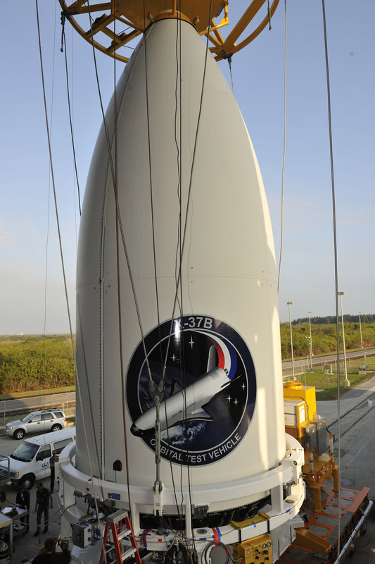
The Payload Fairing is positioned on top of the stacked vehicle and its integrated Payload. It protects the spacecraft against aerodynamic, thermal and acoustic environments that the vehicle experiences during atmospheric flight.
When the launcher has left the atmosphere, the fairing is jettisoned by pyrotechnical initiated systems. Separating the fairing as early as possible increases launcher performance. The Atlas V 551 Rocket features fairings with a diameter of 5.4 meters.
Three different fairing lengths are available: 20.7, 23.4 and 26.5 meters. Major sections of these payload fairings are the boattail, the cylindrical section, and the nose cone that is topped by a spherical cap. Both fairing and boattail sections consists of Aluminum Skin Stringers and Frame Clamshells.
The fairing is separated by a Linear Piston and Cylinder activated by a pyrotechnic cord to achieve vertical separation.
Horizontal separation is accomplished with an expanding tube shearing a notched frame initiated by a pyrotechnic core. Payload Fairings are outfitted with acoustic panels, access doors and RF windows. Optional fairing hardware includes thermal shields and ECS doors. Also, the Payload Fairing is connected to a purge air system to ensure a controlled environment.
Payload Adapter
Payload Adapters interface with the vehicle and the payload and are the only attachment point of the payload on the Launcher. They provide equipment needed for spacecraft separation and connections for communications between the Upper Stage and the Payload.
The separation system can be based on either the traditional pyrotechnical-initiated bolt cutters/separation nuts or Low-Shock Marmon Type Clamp Band Separation System. For Atlas V, a Launch Vehicle Adapter interfaces with the SIP (Standard Interface Plane) of the Launcher and connects to the Standard Payload Adapter or custom-made adapters. Four off-the-shelf adapters are available to accommodate various payloads. Also, custom made fairings can be fitted atop the Launch Vehicle Adapters to accommodate a variety of different payload requirements.
