
Angara A7
Angara A7 is the super-heavy lifter in the Russian Angara launch vehicle family that is operated by the Khrunichev State Research and Production Center. The launcher family includes, light, medium and heavy lift rockets to cover the entire range of payloads and orbits.
The Angara A7 launch vehicles, designated A7.2 and A7.2B, are at the concept stage only without any firm plans to build and launch them in the near-future, but plans have been outlined to fly the A7 around 2025 to 2030.
Although the Angara A7 still uses the Universal Rocket Module that is featured across the Angara family, the launcher represents a step away from the high degree of commonality between the Angara vehicles by using a modified first stage, and eliminating the URM-2 as second stage to utilize a large cryogenic second stage. Also, Angara A7 would require a different launch table than the other Angara vehicles that can share one pad.
The Angara A7.2 vehicle has a Low Earth Orbit Payload capability of 35,000 Kilograms, surpassing any Russian launch system flown to date except for the Energia launcher that flew twice in 1987 and 1988. Angara A7.2 can deliver payloads of up to 12,500 Kilograms into Geostationary Transfer Orbit and insert up to 7,600 Kilograms directly into Geosynchronous Orbit. The larger A7.2 variant has a LEO capability of 50,000 Kilograms.
>>>Angara Launch Vehicle Family
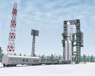
Angara will be operated from the Plesetsk Cosmodrome and the Vostochny Cosmodrome that is currently under construction. A launch facility in Baikonur is also planned, primarily for launches of the Angara A5 vehicle, but the launch pad system for Angara can be used by all launcher versions except for Angara A7.
Angara A7.2 Specifications
| Type | Angara A7.2 |
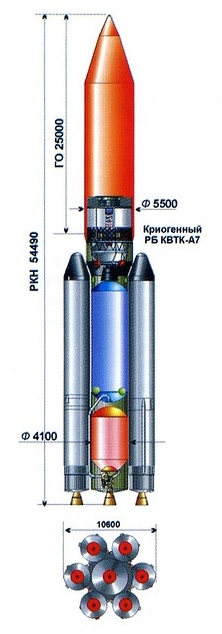
| Length | 54.5m |
| Core Diameter | 4.1m |
| Span | 10.6m |
| Launch Mass | 1,133,000kg |
| Stages | 2 |
| Boosters | 6 |
| Mass to LEO | 35,000kg |
| Mass to GTO | 12,500kg |
| Mass to GEO | 7,600kg |
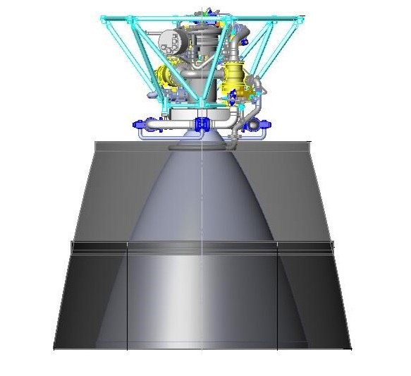
The Angara A7.2 launch vehicle uses six Universal Rocket Modules strapped onto a Core Stage.
Unlike the other Angara launchers, the Core Stage is not a URM as well but a modified version with a larger diameter to carry more propellants which is possible due to the thrust of seven RD-191 engines that create a sufficient thrust-to-weight ratio at launch. Angara A7.2 uses a cryogenic upper stage for a maximum performance to increase the payload capability of the Angara A7.
Overall, the Angara A7.2 launcher stands 54.5 meters tall with a core diameter of 4.1 meters. From side to side, the vehicle measures approximately 10.6 meters. Fully fueled, the Angara A7 weighs approximately 1,133 metric tons with a total liftoff thrust of 1,372 metric-ton-force..
Core Stage
| Type | Modified URM-1 |
| Length | 25.695m |
| Diameter | 4.1m |
| Fuel | Kerosene (RP-1) |
| Oxidizer | Liquid Oxygen |
| Inert Mass | ~14,000kg |
| Propellant Mass | ~240,000kg |
| Launch Mass | ~254,000kg |
| Propellant Tanks | Aluminum Alloy, Intertank Section |
| Tank Pressurization | Helium |
| Propulsion | RD-191 |
| Engine Type | Staged Combustion |
| Thrust – Sea Level | 1,922kN |
| Thrust – Vacuum | 2,085kN |
| Specific Impulse SL | 311.4s |
| Specific Impulse Vac | 337.5s |
| Throttle Range | 27-105% |
| Mixture Ratio | 2.63 |
| Engine Diameter | 2.10m |
| Engine Length | 3.78m |
| Engine Dry Weight | 2,290kg |
| Engine filled Weight | 2,520kg |
| Chamber Pressure | 262.6bar |
| Burn Time | ~380s |
| Guidance | Inertial |
| Pitch/Yaw Control | Hydraulic Engine Gimbaling +/-8° |
| Roll Control | 4 Nozzles & Control Surfaces |
| Engine Start | Pyrophoric TEA |
| Restart Capability | No |
| Stage Separation | Cold Staging |
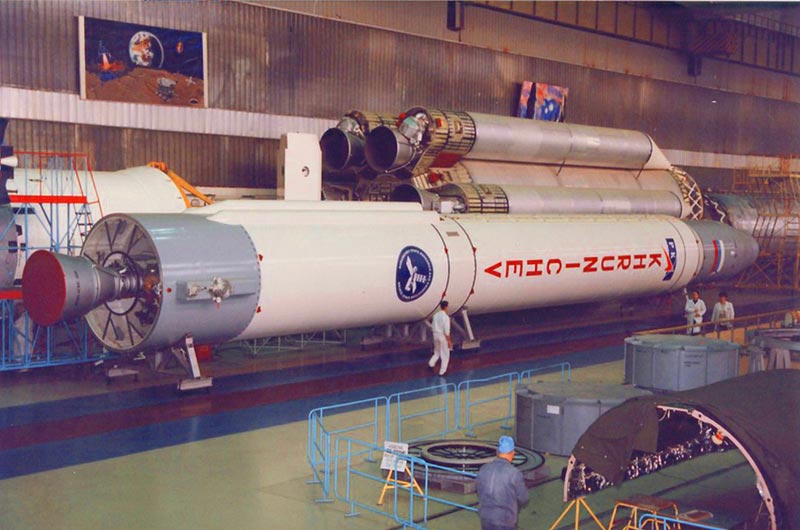
The Core Stage of the Angara A7.2 launcher is a modified version of the Universal Rocket Module that is used across the entire Angara family as a core stage and strap-on booster.
Angara A7.2 uses the URM in its original form as booster while the core is a modified version with a diameter of 4.1 meters as compared to the original diameter of 2.9 meters.
The modified URM-1 keeps the original length of 25.7 meters, but due to the larger diameter has an increased inert mass of about 14 metric tons.
It can carry about 240 metric tons of Kerosene and LOX propellants.
Although the diameter of the tanks is widened, the core stage retains the basic elements and characteristics of the URM such as structural components, the RD-191 propulsion system and the control system.
Changes to the design include the larger tanks and bulkhead structures, an extended nozzle of the RD-191 engine for optimized thrust & impulse in vacuum and additional Helium tanks required to pressurize the larger tanks.
The Core Stage launches with its RD-191 engine at full thrust, but can throttle down during the boost stage of the flight while the boosters continue to propel the launcher at full thrust.
This allows the core stage to save propellants for use after the boosters separate when the core throttles up again. The exact flight profile will depend on the target orbit. In total, the 4.1 meter core stage could burn for close to six and a half minutes.
The modified URM directly interfaces with the large payload fairing of Angara A7.2 that protects the uppermost portion of the KVTK-A7 upper stage and the payload.
The core stage is equipped with an interstage section that structurally connects it to the upper stage and also protects the upper stage engine compartment, separating with the core stage.
Boosters – Universal Rocket Module
When used as a strap-on booster, the Universal Rocket Module uses an aerodynamic nose fairing that is attached to the top of the vehicle, covering the top portion of the upper bulkhead of the Liquid Oxygen Tank. The nose cap utilizes light-weight composite materials. The caps are approximately 2.4 meters tall.
The URM boosters interface with the core stage at three points using spar booms that firmly hold the booster URMs in place secured to the core stage. Thrust from the boosters is transferred to the vehicle via the upper spar boom that interfaces with the interstage section of the core stage and the KVTK upper stage.
When being used as a booster, the URM fires its RD-191 at full throttle throughout the booster stage of the flight with the exception of a throttle down around Maximum Dynamic Pressure. Firing at full thrust, the boosters consume their 132,600-Kilogram propellant load faster than the core that throttles down quickly after liftoff. The boosters burn for 214 seconds before separating from the Core Stage that then throttles up for the rest of its burn.
Separation of the boosters is accomplished using pyrotechnic bolts that disconnect the spar booms between the boosters and the core stage. Solid-fueled retrorockets are fired to ensure a clean separation without re-contact between the boosters and the core stage.
Universal Rocket Module & RD-191 Engine
| Type | URM-1 (Universal Rocket Module) |
| Length | 25.695m |
| Diameter | 2.90m |
| Fuel | Kerosene (RP-1) |
| Oxidizer | Liquid Oxygen |
| Inert Mass | 9,800kg |
| Propellant Mass | 128,000kg (Partial Propellant Load) |
| Launch Mass | 137,800kg |
| Propellant Tanks | Aluminum Alloy, Intertank Section |
| Tank Pressurization | Helium |
| Propulsion | RD-191 |
| Engine Type | Staged Combustion |
| Thrust – Sea Level | 1,922kN |
| Thrust – Vacuum | 2,085kN |
| Specific Impulse SL | 311.4s |
| Specific Impulse Vac | 337.5s |
| Throttle Range | 27-105% |
| Mixture Ratio | 2.63 |
| Engine Diameter | 2.10m |
| Engine Length | 3.78m |
| Engine Dry Weight | 2,290kg |
| Engine filled Weight | 2,520kg |
| Chamber Pressure | 262.6bar |
| Burn Time | 240s |
| Guidance | Inertial |
| Pitch/Yaw Control | Hydraulic Engine Gimbaling +/-8° |
| Roll Control | 4 Nozzles & Control Surfaces |
| Engine Start | Pyrophoric TEA |
| Restart Capability | No |
| Stage Separation | Cold-Staging |
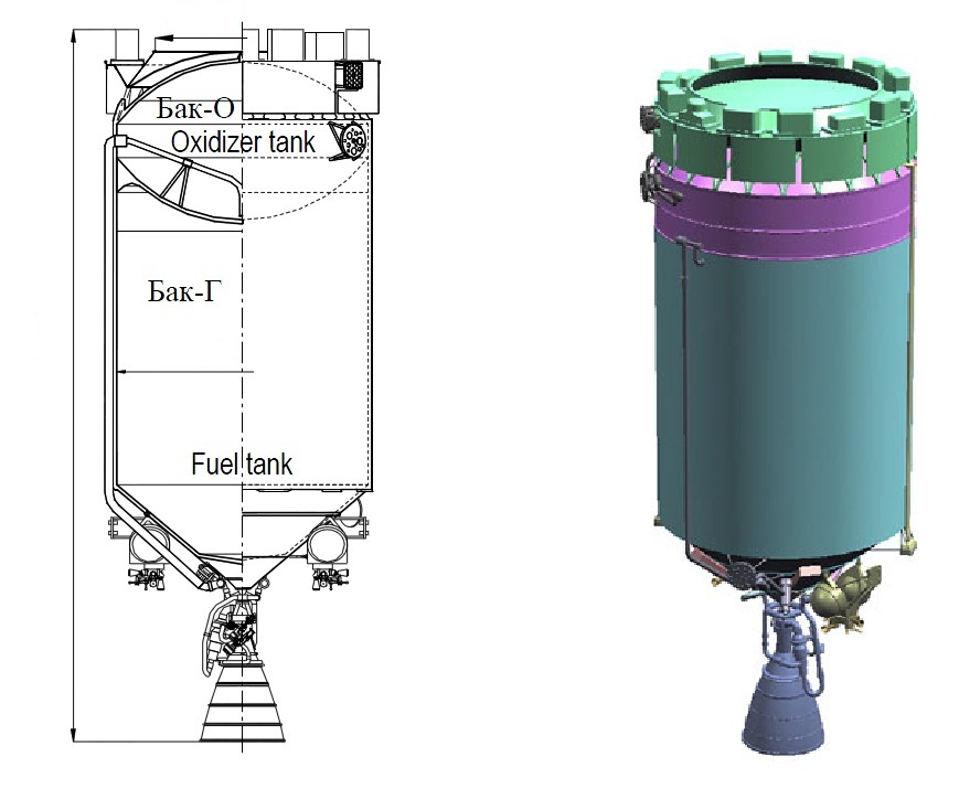
The Universal Rocket Module is common across the entire Angara family – it is used as Core Stage and can also function as a strap-on booster. Being the smallest of the family, Angara 1.2 uses only one URM acting as first stage. The URM is 25.7 meters long and 2.9 meters in diameter featuring the common structure with the oxidizer tank located above the fuel tank. The URM, when fully fueled, has a launch mass of 141,500 Kilograms with an empty mass of just under ten metric tons.
URM uses Liquid Oxygen as oxidizer and rocket-grade Kerosene fuel, stored in tanks consisting of hemispherical bulkheads and cylindrical sections. Aluminum alloy is used to manufacture the tanks and the URM uses composite materials in its interstage and instrument bay utilizing lessons learned from improvements of the Proton rocket that allow Angara to make use of production techniques creating light-weight components. The LOX feedline is routed on the exterior of the Kerosene tank to reach the engine compartment. The two tanks use individual bulkheads, creating an intertank area which is used to accommodate various instrumentation and control equipment.
Spherical Helium bottles are located inside the Liquid Oxygen tank to be submerged in LOX to improve gas storage efficiency. Helium is used for tank pressurization in flight, being heated up and fed to the tanks to keep them at the proper pressure levels. Helium loading begins once the bottles are submerged in Liquid Oxygen in order to be chilled down to accommodate the Helium.
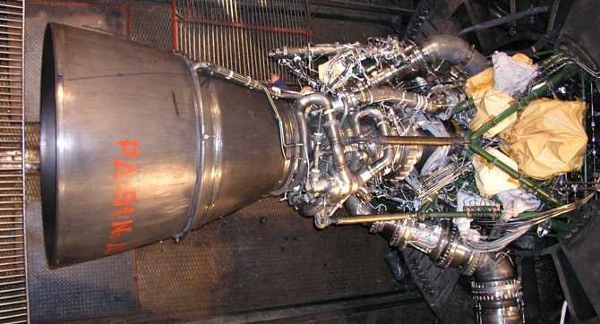
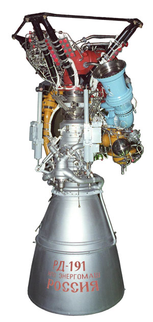
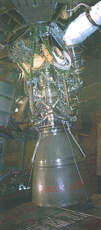
The Universal Rocket Module is powered by a single RD-191 engine which is a one-chamber version of the RD-171 engine used on the Zenit rocket that is based on the RD-170 designed for the Energia rocket. The NPO Energomash RD-171 had already been converted to the two-chamber RD-180 currently used on the Atlas V launch vehicle. In the process of designing the RD-180, a study of creating a one-chamber version was conducted and the development of the engine was started in the late 1990s.
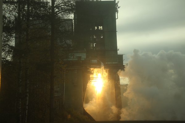
The first test firing was conducted in 2001 and the total testing program included 120 firings with a cumulative duration of 26,892 seconds. RD-191 completed its test program in 2011 and was certified in 2013 after another 18 firing tests.
Overall, RD-191 is 3.78 meters tall and has a nozzle diameter of 2.1 meters. The engine has an inert mass of 2,290 Kilograms. RD-191 is attached to the launcher via a gimbal truss and a spacer to the shell of the lower fuel tank.
RD-191 delivers a sea level thrust of 1,922 Kilonewtons (196,000kgf) with a specific impulse of 311 seconds. Thrust rises to 2,085kN (212,600kgf) in vacuum conditions with a vacuum impulse of 337.5 seconds. Through its design, RD-191 is capable of extremely deep throttling down to 27% of nominal performance. In flight, RD-191 will normally be throttled down no lower than 30%. The engine can also operate at 105% of rated performance for short periods of time which is utilized in contingency scenarios.
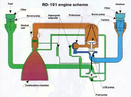
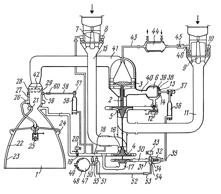
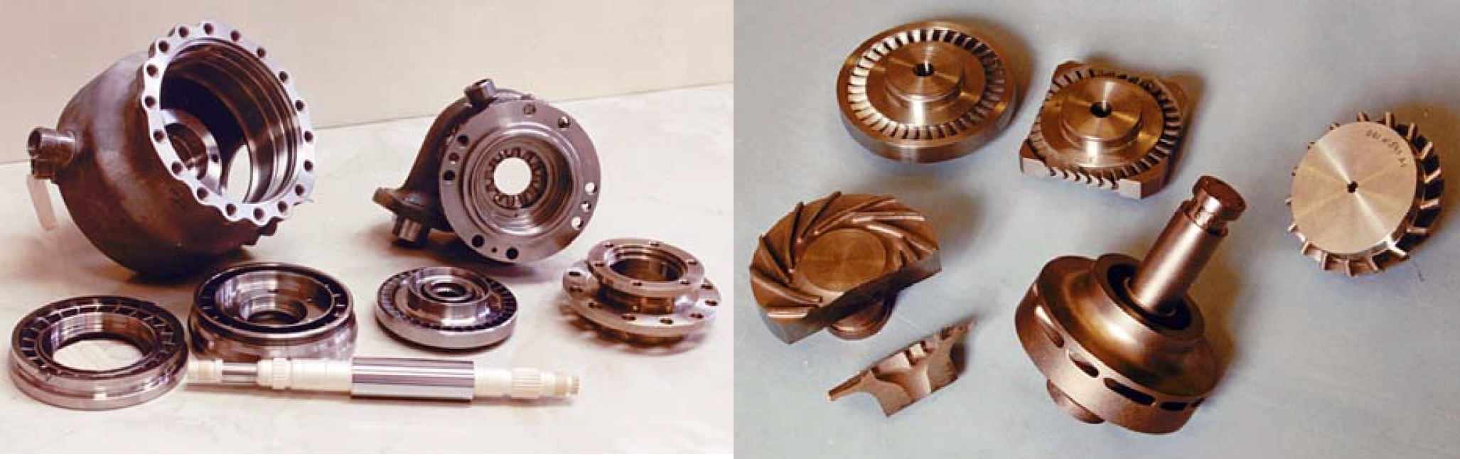
RD-191 uses a staged combustion scheme – burning all of the oxygen with little fuel inside a Gas Generator to produce a hot high-pressure gas to drive the turbine that powers the fuel and oxidizer turbopumps. The engine features boost pumps at the fuel and oxidizer inlets that operate at a lower speed than the main pumps and create an engine inlet pressure sufficient for the operation of the turbopumps. The fuel boost pump is powered by a turbine driven by the fuel tapoff from one main pump (fuel returns to the inlet) and the oxidizer boost pump turbine is driven by a fraction of the hot gas from the gas generator that then enters the LOX flow and condenses.
All of the oxygen is then directed to the LOX impeller turbopump before reaching the Gas Generator. The Kerosene flow is directed into two portions using a two-stage turbopump. The Kerosene flow from the second pump stage (about 20% of total flow) is directed into the Gas Generator were it is burned in an excess of oxidizer, creating a high-pressure, oxygen-rich gas that drives the turbine. The RD-191’s LOX turbopump and fuel pumps are mounted on a single shaft. The turbine itself is a axial turbine using relatively thick blades and large clearance between the gas inlet and the blades to reduce the risk of damage. Nickel-alloys are used to endure the hot temperatures of the gas from the generator and the turbine uses cold oxygen for additional cooling.
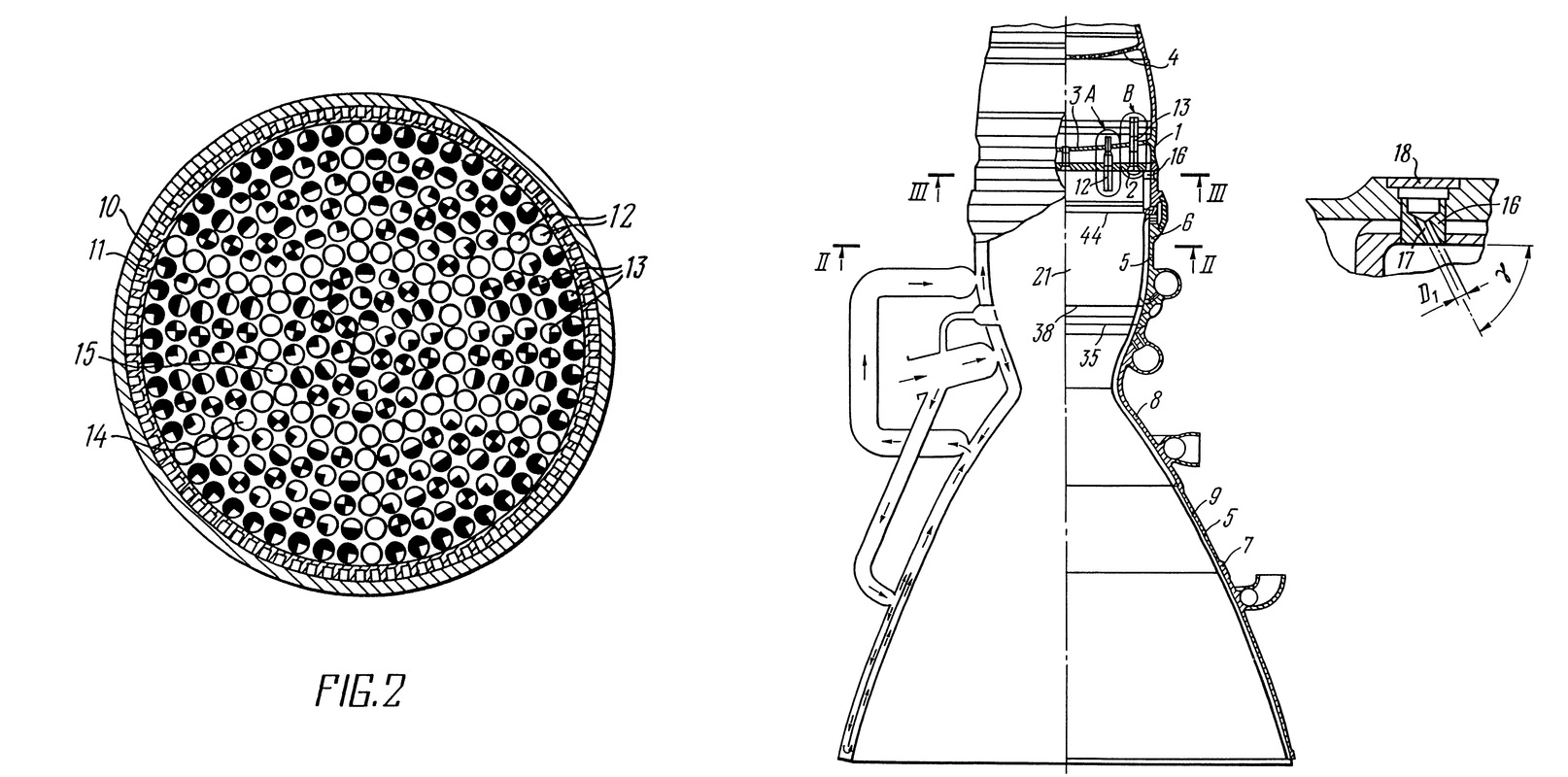
The Kerosene from the first stage pump is directed to the combustion chamber and nozzle where it passes through heat exchangers as part of the regenerative cooling scheme of the engine. The engine uses three cooling paths, one entering at the combustion chamber, one entering at the nozzle throat and the third one entering at the nozzle exit. After passing through the heat exchangers, the fuel is pumped into the combustion chamber where it is burned by the oxygen-rich gas coming from the gas generator. The mixture ratio is adjusted by a mixing valve located behind the first stage turbopump and the Gas Generator Temperature and engine thrust are regulated via flow valves ahead of the Gas Generator. RD-191 has a nominal mixture ratio of 2.63.
Regenerative Cooling Flow
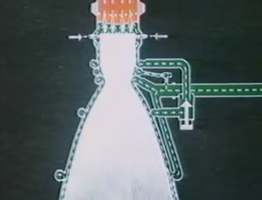
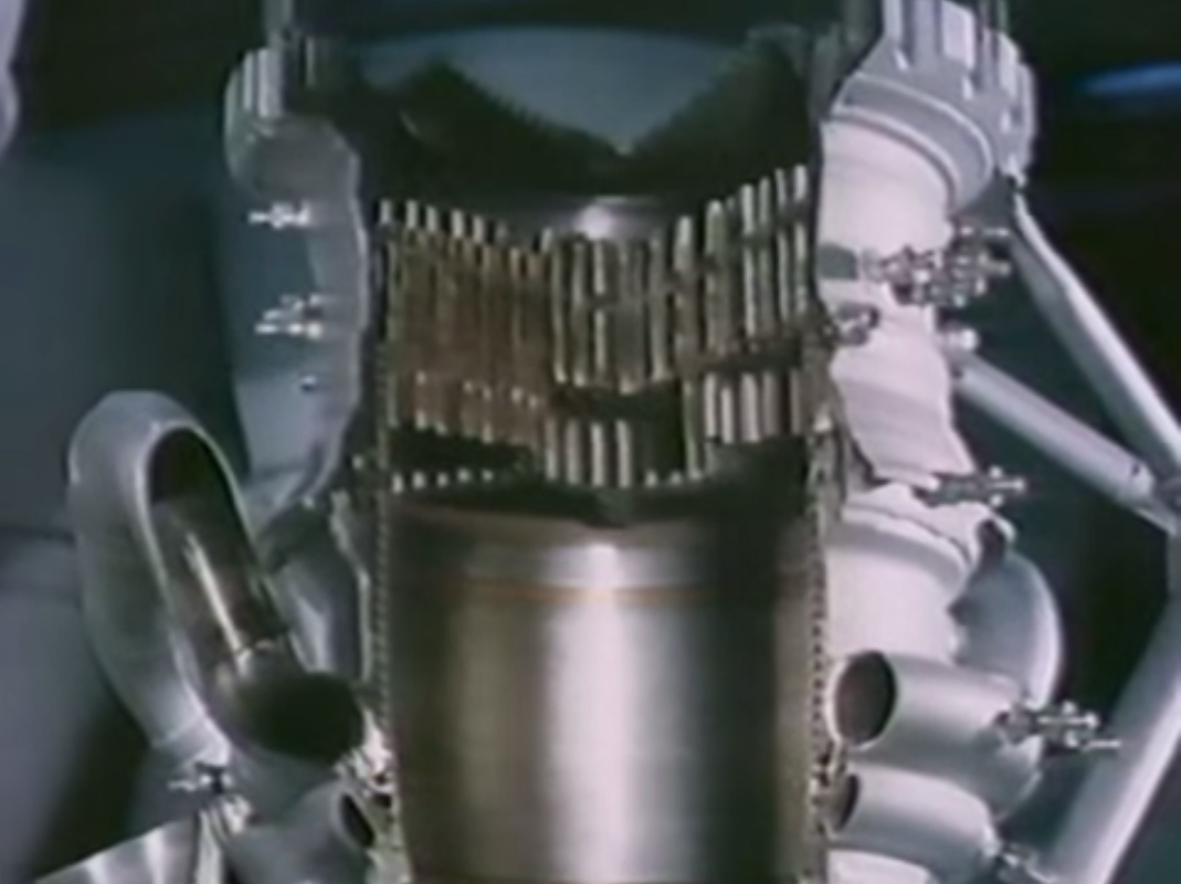
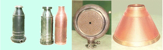
RD-191’s chamber consists of the mixing head, the combustion chamber and the nozzle. The injector uses small nozzles through which the components are introduced into the combustion chamber, forming a circular inner zone separated from an outer ring by protruding nozzles.
The outer ring is divided into six compartments using protruding nozzles through which propellants enter the chamber. Fuel and oxidizer-rich gas alternates between the seven compartments. This design allows a stable combustion and avoids combustion instability or the creation of hot spots. RD-191 operates at a nominal chamber pressure of 262.6 bar.
.
RD-191 Mixing Head & Chamber Design
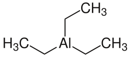
RD-191 uses a chemical ignition system based on Triethylaluminium (TEA) – a pyrophoric substance that immediately ignites upon exposure to oxygen. The TEA is stored in two closed ampoules – one in the fuel line directly ahead of the Gas Generator and one in the main fuel inlet to the combustion chamber. These ampoules use membranes to prevent the TEA from coming into contact with air.
For engine start, a dedicated spherical Kerosene, tank that is connected to both fuel lines via plumbing and associated valves, is filled with fuel and pressurized using high-pressure gas. Once the valves to the fuel lines and ampoules are opened, the high-pressure fuel drives pistons that are part of the ampoules to create a pressure inside the cavity that causes the TEA to be released into the Gas Generator and combustion chamber that have been filled with oxygen by that point after LOX valves are opened and the tank pressure causes oxygen to enter the engine.
Coming into contact with oxygen, the TEA ignites and starts the combustion process inside the Gas Generator and the main chamber. The combustion is sustained by Kerosene entering the GG and combustion chamber right after the TEA. Once the Gas Generator is running, the turbine spins up to speed and the turbo and boost pumps begin pumping propellants to the Gas Generator and Combustion Chamber, thus sustaining the combustion process.
Using this ignition technique means that RD-191 can only be ignited once and requires extensive refurbishment after each ignition (replacing the TEA membranes and re-filling the ampoules).
For tank pressurization, Helium flows from the Helium spheres inside the LOX tank down to the engine compartment where it is heated up inside a heat exchanger connected to the hot gas flow from the Gas Generator to the LOX Boost Pump. The pressurized heated Helium is then pressed into the LOX and Kerosene tanks to keep them at the proper pressure via a series of valves that control the pressurization. The initial pre-flight pressurization is accomplished using pressurized gas supplied by ground support equipment.
RD-191 uses a cardan suspension which allows it to gimbal +/-8 degrees using a hydraulic system driven by the gas generator exhaust. Engine gimbaling can only achieve control on the pitch and yaw axis requiring an additional system for roll control.
For that, hot has from the RD-191 gas generator is released through four nozzles onto two aerodynamic control surfaces that deflect the stream of hot gas and introduce a roll component depending on their position. The control surfaces on the outside of the tail section are moved using hydraulic pressure.
Being a modern engine, RD-191 includes various pressure, flow and temperature sensors that provide detailed performance data to the engine controller and flight computers. This allows a detailed monitoring of performance and extensive post flight analysis which can be useful in case of any anomalies. Also, telemetry is used in real time by the vehicle’s control system to adjust engine parameters like mixture ratio to optimize the performance of the launch vehicle via optimal propellant utilization. Additionally, engine telemetry is used to trigger launch vehicle abort modes.
The Universal Rocket Module houses control system devices, telemetry measurement systems, power supply units and batteries inside the intertank section. The URM control system is common across the entire Angara family and uses heritage components from the Proton-M and Briz-M vehicles. Functions of the URM control system include control of the engine, monitoring of propellant consumption, monitoring of vehicle health, engine gimbal control, control of aerodynamic surfaces and telemetry transmission to the ground.
The control equipment is self-contained and inertial using a modular structure that permits the addition of components at minimal difficulty. URM houses its own inertial guidance unit and also receives commands from the digital flight control system facilitated on the second stage.
Unlike the Soyuz, Angara uses a cold-separation sequence between the URM-1 and the second stage instead of the hot-staging of Soyuz in which the RD-0124 engine ignites before separation to be able to push the spent Core Stage away.
For staging on the Angara launcher, the RD-191 engine is shut down followed by a short delay before the pyrotechnic stage separation sequence is initiated, cutting the structural connection between URM-1 and the second stage. Next, four solid-fueled retrorockets are ignited on URM-1 located in the interstage area. These rockets move the Core Stage away from the second stage, clearing the way for engine ignition after a pre-programmed interval.
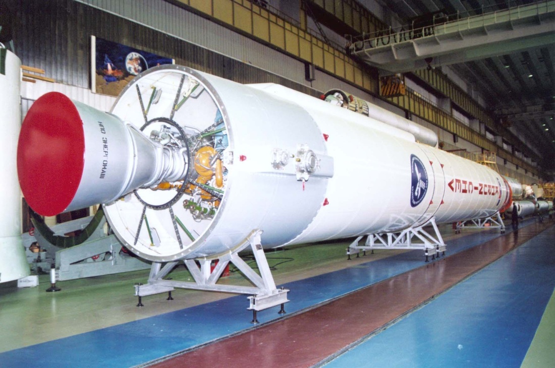
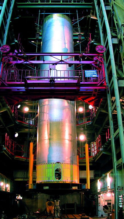
URM Tanks during Assembly

The interstage structure is separated with the first stage and stays attached to it, thus exposing the second stage’s engine compartment. Soyuz uses a three-segment aft section that is jettisoned ten seconds into the engine burn meaning that Angara eliminates one separation event, which are associated with some risk.
Upper Stage – KVTK-A7
| Type | KVTK-A7 |
| Length | 10.7m |
| Diameter | 4.9m |
| Fuel | Liquid Hydrogen |
| Oxidizer | Liquid Oxygen |
| Inert Mass | 3,880kg |
| Propellant Mass | 26,500kg |
| Launch Mass | 31,250kg |
| Tank Pressurization | Helium |
| Propulsion | RD-0146D |
| Engine Type | Expander Cycle |
| Thrust – Vacuum | 68.6kN |
| Specific Impulse Vac | 463s |
| Engine Diameter | 0.96m |
| Engine Length | 3.558m |
| Nozzle Length | 1,95m |
| Engine Mass | 242kg |
| Burn Time | 1,350s |
| Chamber Pressure | 60bar |
| Restart Capability | Up to 5 |
| Settling Thrusters | 16 x 11D428A |
| Fuel | Unsymmetrical Dimethylhydrazine |
| Oxidizer | Nitrogen Tetroxide |
| Thrust | 130N |
| Specific Impulse | 290s |
| Thruster Length | 274mm |
| Thruster Diameter | 93mm |
| Thruster Mass | 1.5kg |
| Burn Time | 0.03s (Impulse) – 2,000s |
| Cycle Life | 500,000 |
| Reaction Control | 16 x S5.142A |
| Fuel | Unsymmetrical Dimethylhydrazine |
| Oxidizer | Nitrogen Tetroxide |
| Thrust | 25N |
| Attitude Control | Engine Gimbaling, RCS |
| Flight Duration | Up to 9 Hours |
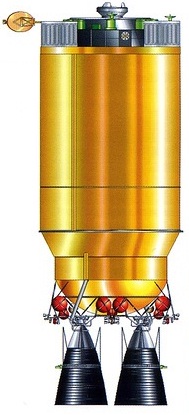
The KVTK-A7 cryogenic upper stage is a larger version of the KVSK and basic KVTK stages used on the Angara A3 and A5 versions. KVTK-A7 features a larger diameter with bigger and stretched tanks to hold more propellant than the smaller KVTK versions. Across the family of cryogenic upper stages, a lot of commonality exists extending the principle of the Angara family – using common components or scaled-up parts to create a simplified assembly and integration process and to cut costs.
In addition to its larger size, the KVTK-A7 stage implements a number of changes compared to the smaller versions of the cryogenic upper stage. These include the addition of propellant settling thrusters and attitude control jets to be able to control the larger stage.
KVTK is a single-stage booster consisting of a propellant compartment, an upper equipment compartment and a lower engine compartment. In its operational configuration, the upper stage is enclosed in the Angara payload fairing for protection. The engine compartment is not protected by the fairing and needs to be enclosed in a separable interstage section that builds the interface to the second stage, also including electrical and data interfaces.
KVTK-A7 is approximately 10.7 meters long and 4.9 meters in diameter with a launch mass of 31,250 Kilograms. It uses cryogenic propellants – liquid Oxygen and liquid Hydrogen for its main propulsion system centered around the RD-0146D engine. Hypergolic propellants are used for the propellant settling thrusters and the attitude control system. Helium is used for tank pressurization stored in spherical high-pressure tanks.
The tanks of the KVTK upper stage are made of aluminum alloy using spherical bulkheads with a cylindrical section between the bulkheads capable of holding 26,500kg of cryogenics. The tanks use insulation materials (isolane and screen thermal vacuum insulation) and the propellant lines are covered with insulation as well. This is required to prevent an excessive boil-off inside the tanks which is a problem during extended flight profiles. KVTK uses separable connectors for the LOX/LH2 and Helium fill & drain systems that interface with ground support equipment on the launch pad and separate a liftoff. Ground purge flow is directed into the engine compartment and the payload fairing as part of KVTK’s fire prevention system. These interfaces also separate at launch. With the second stage, KVTK communicates using umbilical connectors that are separated at staging and communication with the spacecraft is accomplished through interfaces on the payload adapter.
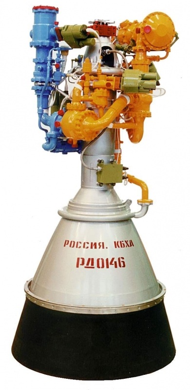
The RD-0146D engine is based on the original RD-0146 built by the KBKhA design bureau in cooperation with Pratt & Whitney Rocketdyne to design a Russian-equivalent to the RL-10 engine that is used to power the Centaur Upper Stage (Atlas) and the Delta Cryogenic Second Stage (Delta IV). RD-0146 is the first Russian engine not using a gas generator and the first to feature a deployable nozzle extension.
Development of the RD-0146 engine started in 1997 at KBKhA and was partially financed by Pratt & Whitney Rocketdyne, giving the company the international marketing right of the engine. This marked the first step toward Russia’s return to fully cryogenic rocket fuel since the Energia rocket demonstrated the difficulty to control the LOX/LH2 combination in the 1980s. It also is KBKhA’s first engine with separate turbopumps, stepping away from the single-shaft design.
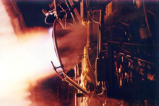
The design of the engine was finished in 2001 and the first components had already been produced by then including ball valves with minimal leakage for Hydrogen. First, engine components were tested individually, such as the igniter. Late in 2001, the first RD-0146 was test fired to start its test program that was completed in 2007. RD-0146 is an expander cycle engine delivering 98.1 Kilonewtons of thrust with a nozzle optimized for operation in vacuum to create a specific impulse of 463 seconds.
With the basic RD-0146 design and development complete, efforts to extend the engine’s capabilities were started to create the RD-0146D with deployable nozzle extension and multiple ignition capability, and the RD-0146DM that uses Liquid Natural Gas instead of liquid hydrogen. RD-0146D has a lower thrust than the original version, but a higher vacuum impulse due to the use of the extended nozzle – it also supports long burns of more than 1,300 seconds. The RD-0146DM variant has a lower thrust and impulse due to the different propellant combination and has not yet been certified for long burns. The D and DM versions began development in 2007 & 2008 – the first test firings began in 2012. The RD-0146D completed vacuum testing, multiple ignition tests and tune-up testing in 2013 to be certified for use in 2015.
RD-0146D stands about 3.56 meters tall with its nozzle extension deployed, creating a nozzle diameter of 0.96 meters and a nozzle length of 1.95 meters. The engine weighs about 242 Kilograms and delivers a vacuum thrust of 68.6 Kilonewtons (7,000kgf) at a vacuum impulse of 470 seconds. The engine uses regenerative cooling on its chamber and fixed nozzle segment while the deployable nozzle is cooled radiatively. The carbon-carbon nozzle extension uses an electromechanical deployment mechanism.
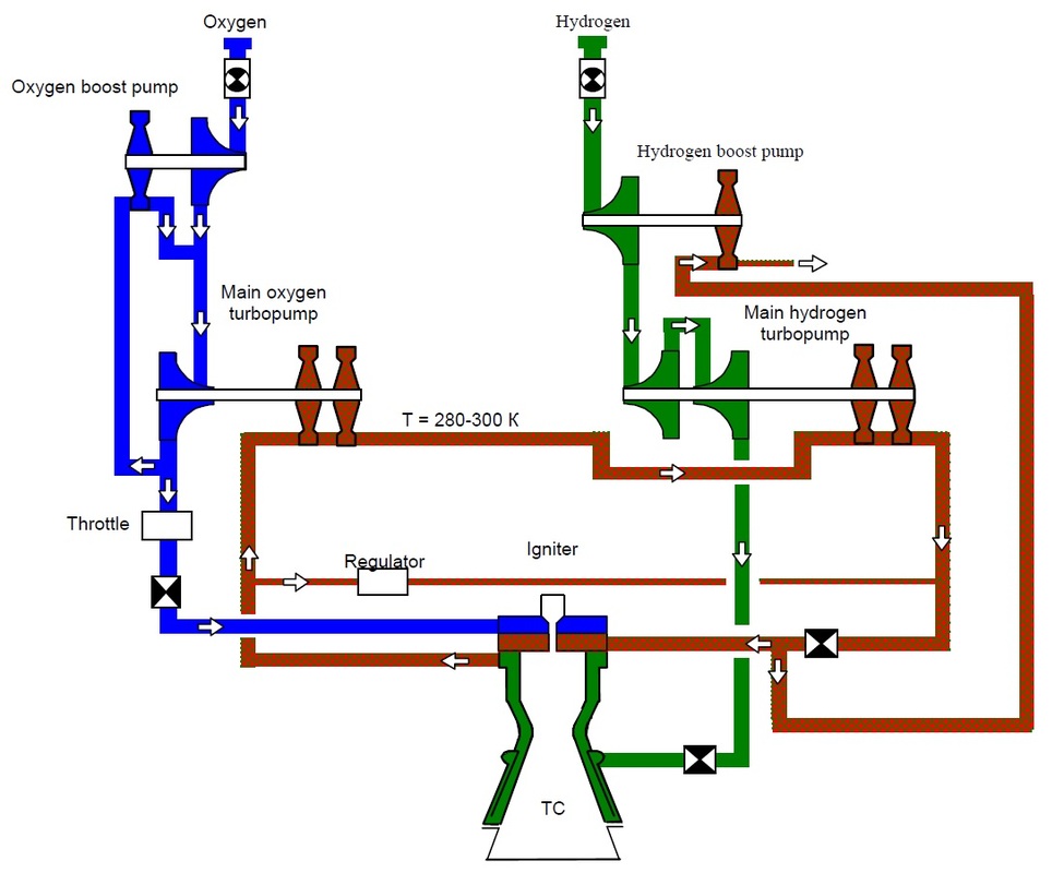
RD-0146D uses an expander cycle that is very different to the staged combustion cycle of gas generator engines. In its principle, the engine expands the hydrogen fuel by running it through the engine heat exchangers to cool the chamber before entering the combustion chamber and being burned with the oxidizer.
The engine uses ball valves in the LOX and LH2 feedlines as engine inlet valves before the propellants run through boost pumps with separate units for the fuel and oxidizer. These boost pumps allow the propellants to be supplied at low pressure (5.1 bar for LOX & 5.7 bar for LH2) and increase the flow and pressure to sufficient levels for the main turbopumps.
The LOX boost pump is operated by a small stream of high-pressure LOX that is taken from the turbopump output, driving the boost pump turbine and being introduced into the LOX flow downstream of the boost pump to enter the cycle again. On the LH2 side, the boost pump turbine is spun by a high-pressure hydrogen stream that is taken from the expanded gas after passing through the turbopump and engine heat exchanger.
After passing the boost pumps, the liquid Oxygen reaches its impeller turbopump that increases the pressure to approximately 130 bar. The LOX turbopump is driven by a turbine that is powered by the hot hydrogen gas from the LH2 turbopump heated & expanded in the heat exchangers. Some of the turbopump output is routed to the LOX boost pump while the rest is directed to the combustion chamber via a regulator for throttle control and a main oxidizer valve. The regulator controls the mixture ratio that is commanded by the engine controller and ensures fuel-rich conditions for start-up and shutdown to maintain chamber integrity. RD-0146 operates at a nominal mixture ratio of 5.9.
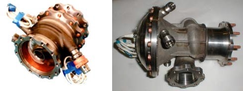
RD-0146 Turbopump Components
The LH2 system uses a two-stage turbopump to reach fuel outlet pressures of around 260 bar. The entire liquid Hydrogen output from the pump is passed through a regulator valve inside the heat exchanger circuit of the engine that cools the combustion chamber and fixed nozzle section and gasifies the hydrogen – rapidly expanding it to be able to drive the pumps and to be injected into the chamber as a gas. After passing through the heat exchangers, the gas has a temperature of 280 to 300 Kelvin. First, the hot gas passes through the LOX turbopump turbine before reaching the LH2 turbopump turbine. The two LH2 pumps are mounted on a single shaft driven by one turbine assembly. The turbines can be bypassed by routing the hot gas through a dedicated pipeline via a regulator to be able to control the turbine speed and engine thrust level. A small fraction of the gaseous hydrogen flow is directed to the LH2 boost pump turbine while the rest is injected into the combustion chamber along with the oxidizer.
The combustion chamber uses 200 coaxial injectors to introduce the propellants into the combustion chamber and ensure a stable combustion process. RD-0146D operates at a chamber pressure of around 60 bar with an operational range of 40 to 112.5%. Combustion efficiency of the injectors is approximately 99.5%. For its regenerative cooling scheme, the chamber features an elongated cylindrical section that has over 200 longitudinal fins on its outside to be able to transfer the heat to the hydrogen that is flowing past. The fins reach temperatures of up to 900K.
RD-0146 Components
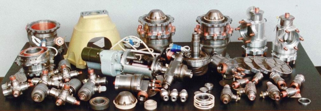
The turbopumps of the RD-0146 can spin at up to 123,200rpm, but the RD-0146D only requires pump speeds of around 98,180rpm. For engine start, a hydrogen-rich mixture is injected into the chamber and ignited with an electric-plasma igniter that operates under low-pressure with excess oxygen. The igniter allows up to five re-starts in flight. Once the fuel-rich mixture is ignited, the engine is operated fuel rich at a reduced thrust level for some time to allow the turbopumps to spin up so that a stable combustion process can be achieved for the throttle-up to 100%. Shutdown is also completed in fuel-rich conditions. To prevent cavitation, the engine is chilled down ahead of each start.
RD-0146 uses pneumatic and electromechanical actuators for all of its valves and regulators. The engine also uses a number of pressure, temperature and flow-rate sensors to provide real-time insight into engine health, allow the engine controller to monitor the state of the engine and make adjustments of the mixture ratio and to enable detailed post flight analysis of the engine’s performance. RD-0146 uses nickel-based alloys and titanium and aluminum alloys for the chamber, the turbopump housing and the various pipelines. Stainless steel with coatings are used for turbopump blades.
The RD-0146D engine can be gimbaled in two planes by up to +/-4 degrees to provide pitch and yaw control during powered flight while roll control is provided by the reaction control system.
The KVSK upper stage uses a propellant settling thruster system and an attitude control system consuming hypergolic propellants – Unsymmetrical Dimethylhydrazine and Nitrogen Tetroxide. The propellants are stored in spherical high-pressure tanks that use a bladder pressurization system supplied by the Helium tanks of the KVSK stage.
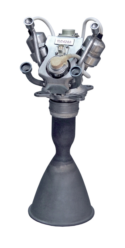
For propellant settling inside the tanks, eight thrusters are installed on the vehicle to ignite before a main engine burn (10-15 seconds) to provide an acceleration to the vehicle so that the propellants inside the stage’s tanks reach a two-phase composition ensuring that only liquid propellants enter the main engine. These eight thrusters are 11D28A engines which are also used as DPO-A orbit correction and attitude control thrusters on the Soyuz spacecraft. Each thruster delivers 130 Newtons of thrust (13.3kgf) measuring 24.7 centimeters in length and 9.3 centimeters in diameter with a mass of 1.5 Kilograms. The thrusters have a specific impulse of 290 seconds and can be operated in pulse mode for attitude control and steady-state mode with burns up to 2,000 seconds for propellant settling. The eight settling thrusters can also be used for insertion accuracy optimization after main engine shutdown.
Eight S5.142A attitude control thrusters are installed on two thruster modules located in the engine compartment to provide three-axis attitude control during non-propulsive flight phases and control about the roll axis during main engine firings. Each of these thrusters delivers 25 Newtons of thrust and can be operated in pulse and steady-state modes.
The KVSK upper stage uses a control system similar to the Briz-M. This equipment is housed inside a compartment at the top of the stage and interfaces with all components of the upper stage to be ale to control all stages of the flight. Navigation data is provided by a three-axis inertial guidance platform and vehicle control is accomplished by a redundant flight computer system. The system is autonomous and requires no uplink of data, but includes communications equipment to downlink telemetry via direct ground station passes or via the Luch satellite communications system.
KVSK uses batteries to supply power to its various systems and is capable of executing missions of up to nine hours.
Payload Fairing
| Type | A7.2 Fairing |
| Diameter | 5.5m |
| Length | 25.0m |
| Mass | ~4,500kg |
Angara A7.2 uses a very large fairing that protects the upper section of the KVTK-A7 cryogenic second stage and offers enough payload volume for a variety of spacecraft including large space station modules.
The 25-meter long fairing interfaces with the interstage between the core stage and the KVTK-A7 upper stage.
.
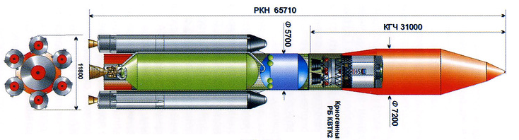
Angara A7.2B
| Type | Angara A7.2B |
| Length | 65.7m |
| Core Diameter | 5.7m |
| Span | 11.8m |
| Launch Mass | >? |
| Stages | 2 |
| Core Stage | 5.7m LH2/LOX |
| Propulsion | RD-0120 (?) |
| Boosters | 6 |
| Boosters | URM-1, 2.9m, LOX/Kerosene |
| Booster Propulsion | RD-191 |
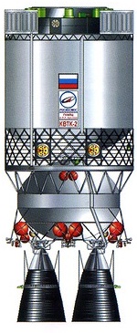
| Second Stage | KVTK2-A7 or KVTK2B-A7 |
| 2nd Stage Propulsion | 2 x RD-0146 |
| Payload Fairing | Length: 31m, Diameter: 7.2m |
| Mass to LEO | 50,000kg |
| Mass to GTO | 19,000kg |
| Mass to GEO | 11,400kg |
50 metric-ton LEO Capability
Core Stage Diameter Increased to 5.7 meters
Core Stage Propulsion switched to Liquid Oxygen & Liquid Hydrogen
Cryogenic Engine with extended Nozzle
Six URM-1 Boosters (Kerolox) with one RD-191 each
Total Launch Thrust of 13,050 Kilonewtons
Dual-engine KVTK2-A7 or KVTK2B-A7 Upper Stage
Upper Stage Propulsion: Two RD-0146 Engines
.
KVTK2-A7 & KVTK2B-A7 Upper Stage Designs
| Type | KVTK2-A7 |
| Length | 12.4m |
| Diameter | 5.0m |
| Fuel | Liquid Hydrogen |
| Oxidizer | Liquid Oxygen |
| Inert Mass | 5,750kg |
| Propellant Mass | 36,750kg |
| Launch Mass | 43,310kg |
| Type | KVTK2B-A7 |
| Length | 14.0m |
| Diameter | 5.0m |
| Fuel | Liquid Hydrogen |
| Oxidizer | Liquid Oxygen |
| Inert Mass | 6,240kg |
| Propellant Mass | 40,500kg |
| Launch Mass | 48,560kg |
| Tank Pressurization | Helium |
| Propulsion | 2 x RD-0146D |
| Engine Type | Expander Cycle |
| Thrust – Vacuum | 68.6kN |
| Specific Impulse Vac | 463s |
| Engine Diameter | 0.96m |
| Engine Length | 3.558m |
| Nozzle Length | 1,95m |
| Engine Mass | 242kg |
| Burn Time | 1,350s |
| Chamber Pressure | 60bar |
| Restart Capability | Up to 5 |
| Settling Thrusters | 16 x 11D428A |
| Fuel | Unsymmetrical Dimethylhydrazine |
| Oxidizer | Nitrogen Tetroxide |
| Thrust | 130N |
| Specific Impulse | 290s |
| Thruster Length | 274mm |
| Thruster Diameter | 93mm |
| Thruster Mass | 1.5kg |
| Burn Time | 0.03s (Impulse) – 2,000s |
| Cycle Life | 500,000 |
| Reaction Control | 16 x S5.142A |
| Fuel | Unsymmetrical Dimethylhydrazine |
| Oxidizer | Nitrogen Tetroxide |
| Thrust | 25N |
| Attitude Control | Engine Gimbaling, RCS |
